EP4549329A1 - Verpackungsmaschine und verpackungsmaschine zum formen von mit einem fliessfähigen produkt gefüllten verpackungen - Google Patents
Verpackungsmaschine und verpackungsmaschine zum formen von mit einem fliessfähigen produkt gefüllten verpackungen Download PDFInfo
- Publication number
- EP4549329A1 EP4549329A1 EP24208815.1A EP24208815A EP4549329A1 EP 4549329 A1 EP4549329 A1 EP 4549329A1 EP 24208815 A EP24208815 A EP 24208815A EP 4549329 A1 EP4549329 A1 EP 4549329A1
- Authority
- EP
- European Patent Office
- Prior art keywords
- tube
- shell
- operative
- forming apparatus
- rotation axis
- Prior art date
- Legal status (The legal status is an assumption and is not a legal conclusion. Google has not performed a legal analysis and makes no representation as to the accuracy of the status listed.)
- Pending
Links
Images


Classifications
-
- B—PERFORMING OPERATIONS; TRANSPORTING
- B65—CONVEYING; PACKING; STORING; HANDLING THIN OR FILAMENTARY MATERIAL
- B65B—MACHINES, APPARATUS OR DEVICES FOR, OR METHODS OF, PACKAGING ARTICLES OR MATERIALS; UNPACKING
- B65B9/00—Enclosing successive articles, or quantities of material, e.g. liquids or semiliquids, in flat, folded, or tubular webs of flexible sheet material; Subdividing filled flexible tubes to form packages
- B65B9/10—Enclosing successive articles, or quantities of material, in preformed tubular webs, or in webs formed into tubes around filling nozzles, e.g. extruded tubular webs
- B65B9/20—Enclosing successive articles, or quantities of material, in preformed tubular webs, or in webs formed into tubes around filling nozzles, e.g. extruded tubular webs the webs being formed into tubes in situ around the filling nozzles
- B65B9/2049—Package shaping devices acting on filled tubes prior to sealing the filling opening
-
- B—PERFORMING OPERATIONS; TRANSPORTING
- B65—CONVEYING; PACKING; STORING; HANDLING THIN OR FILAMENTARY MATERIAL
- B65B—MACHINES, APPARATUS OR DEVICES FOR, OR METHODS OF, PACKAGING ARTICLES OR MATERIALS; UNPACKING
- B65B65/00—Details peculiar to packaging machines and not otherwise provided for; Arrangements of such details
- B65B65/02—Driving gear
-
- B—PERFORMING OPERATIONS; TRANSPORTING
- B65—CONVEYING; PACKING; STORING; HANDLING THIN OR FILAMENTARY MATERIAL
- B65B—MACHINES, APPARATUS OR DEVICES FOR, OR METHODS OF, PACKAGING ARTICLES OR MATERIALS; UNPACKING
- B65B61/00—Auxiliary devices, not otherwise provided for, for operating on sheets, blanks, webs, binding material, containers or packages
- B65B61/24—Auxiliary devices, not otherwise provided for, for operating on sheets, blanks, webs, binding material, containers or packages for shaping or reshaping completed packages
Definitions
- the present invention relates to a package forming apparatus for a packaging machine for forming packages filled with a pourable product, preferentially a pourable food product.
- the present invention further relates to a packaging machine for forming packages filled with a pourable product, preferentially a pourable food product.
- liquid or pourable food products such as fruit juice, UHT (ultra-high-temperature treated) milk, wine, tomato sauce, etc.
- UHT ultra-high-temperature treated milk
- wine tomato sauce
- etc. are sold in packages made of sterilized packaging material.
- a typical example is the parallelepiped-shaped package for liquid or pourable food products known as Tetra Brik Aseptic (registered trademark), which is made by sealing and folding laminated strip packaging material.
- the packaging material has a multilayer structure comprising a base layer, e.g. of paper, covered on both sides with layers of heat-seal plastic material, e.g. polyethylene.
- the packaging material also comprises a layer of oxygen-barrier material (an oxygen-barrier layer), e.g. an aluminum foil, which is superimposed on a layer of heat-seal plastic material, and is in turn covered with another layer of heat-seal plastic material forming the inner face of the package eventually contacting the food product.
- Packages of this sort are normally produced on fully automatic packaging machines, which advance a web of packaging material through a sterilization apparatus for sterilizing the web of packaging material at a sterilization station and to an isolation chamber (a closed and sterile environment) in which the sterilized web of packaging material is maintained and advanced.
- an isolation chamber a closed and sterile environment
- the web of packaging material is folded and sealed longitudinally at a tube forming station to form a tube having a longitudinal seam portion, the tube being further fed along a vertical advancing direction.
- the tube is filled with a pourable product, in particular a pourable food product, and is transversally sealed and subsequently cut along equally spaced transversal cross sections within a package forming apparatus of the packaging machine during advancement along the vertical advancing direction.
- a pourable product in particular a pourable food product
- each pillow package has a longitudinal sealing band, a top transversal sealing band and a bottom transversal sealing band.
- a typical packaging machine comprises a conveying device for advancing the web of packaging material, the sterilization apparatus for sterilizing the web of packaging material prior to its formation into the tube, a tube forming and sealing device configured to form the tube from the advancing web of packaging material and to longitudinally seal the tube, a filling device for filling the tube with the pourable product and the package forming apparatus adapted to form, transversally seal and cut individual packages from the tube of packaging material.
- the package forming apparatus comprises at least one operative device, typically two operative devices, each having at least a first operative group and a second operative group configured to at least partially form and to transversally seal and cut in cooperation the, in use, advancing tube.
- Each first operative group and each second operative group comprises a respective half-shell configured to at least partially form the tube and a control device for controlling the half-shell.
- Each half-shell comprises a respective main forming plate and two lateral forming plates, which, in use, are brought in contact with the tube so as to at least partially form the tube.
- the control device is configured to control the angular movement of the respective half-shell and is realized to actuate the angular movement of the respective half-shell so that the respective half-shell is brought in contact with the tube.
- a further object of the present invention is to provide a packaging machine for forming packages filled with a pourable product addressing the drawbacks described above and, in particular, being easy and economical to be manufactured.
- a package forming apparatus for a packaging machine for forming packages filled with a pourable product for forming packages filled with a pourable product and a packaging machine for forming packages filled with a pourable product according to the appended claims.
- Number 1 indicates as a whole a packaging machine for producing sealed packages 2 of a pourable product, in particular a pourable food product, such as milk, milk drinks, yoghurt, yoghurt drinks, fruit juice, wine, tomato sauce, emulsions, beverages containing pulp, salt, sugar, etc.
- a pourable food product such as milk, milk drinks, yoghurt, yoghurt drinks, fruit juice, wine, tomato sauce, emulsions, beverages containing pulp, salt, sugar, etc.
- packaging machine 1 may be configured to produce packages 2 from a multilayer packaging material.
- a multilayer packaging material having heat seal properties i.e. portions of the multilayer packaging material can be sealed to one another.
- the multilayer packaging material may comprise at least one layer of fibrous material, such as e.g. paper or cardboard, and at least two layers of heat-seal plastic material, e.g. polyethylene, interposing the layer of fibrous material in between one another.
- one of these two layers of heat-seal plastic material may define the inner face of packages 2 contacting the pourable product.
- the multilayer packaging material may also comprise a layer of gas- and light-barrier material, e.g.
- the packaging material may also comprise a further layer of heat-seal plastic material being interposed between the layer of gas- and light-barrier material and the layer of fibrous material.
- the multilayer packaging material may be provided in the form of a web 3.
- packaging machine 1 is configured to produce packages 2 by forming a tube 4 from the web 3, longitudinally sealing the tube 4, filling the tube 4 with the pourable product and to transversally seal, and preferentially transversally cut the tube 4.
- each package 2 extends along a longitudinal axis A and comprises at least a first transversal sealing band 5, and preferentially also a second transversal sealing band arranged at opposite ends of the package 2.
- each package 2 also comprises a longitudinal seam portion 6.
- each first transversal sealing band 5 and/or each second transversal sealing band are transversal (preferentially perpendicular) to the respective longitudinal seam portion 6.
- packaging machine 1 comprises:
- the packaging machine 1 comprises an isolation chamber 14, preferentially delimiting an inner environment 15 from an outer environment 16.
- inner environment 15 is a sterile (aseptic) environment, preferably containing a controlled atmosphere.
- the tube forming and sealing device 12 is at least partially arranged within the isolation chamber 14, in particular within the inner environment 15, and is configured to fold and longitudinally seal the tube 4 within the isolation chamber 14, in particular within the inner environment 15.
- the packaging machine 1 comprises a sterilization unit configured to sterilize the advancing web 3, preferentially the sterilization unit is arranged upstream of the tube forming and sealing device 12 along the web conveying path P.
- the conveying device 11 is configured to advance the tube 4 (even when partially formed) along the tube conveying path Q, preferentially from the tube forming and sealing device 12 to and/or at least partially within the package forming apparatus 10.
- the tube forming and sealing device 12 comprises at least two forming ring assemblies 17, preferentially arranged within the isolation chamber 14, even more preferentially arranged within the inner environment 15, configured to gradually fold in cooperation with one another the web 3 into the tube 4, preferentially by overlapping opposite longitudinal edges of the web 3 with one another. Thereby, in use, the seam portion 6 is formed.
- the tube forming and sealing device 12 comprises a sealing head 18, preferentially arranged within the isolation chamber 14, even more preferentially within the inner environment 15, and, configured to longitudinally seal the tube 4, preferentially along the longitudinal seam portion 6.
- the filling device 13 comprises a filling pipe 19 configured to direct the pourable product into the tube 4.
- the filling pipe 19 is at least partially placed within the tube 4 for feeding, in use, the pourable product into the tube 4.
- the package forming apparatus 10 comprises a number of operative devices 25 (only partially shown to the extent necessary for the comprehension of the present invention).
- the package forming apparatus 10 comprises two operative devices 25.
- a first operative device is indicated with 25* in figures 3 and 4 and a second operative device is indicated with 25** in figures 3 and 4 .
- the first operative device 25* is arranged in an upper position (i.e. is positioned above the second operative device 25** along an advancement direction of the tube 4) and the second operative device 25** is arranged in a lower position (i.e. is positioned below the first operative device 25* along the advancement direction of the tube 4).
- Each operative device 25 is configured to at least partially form, and preferentially to transversally seal and/or transversally cut the tube 4.
- the package forming apparatus 10 is configured to control each operative device 25 such to at least partially form the tube 4 between two spaced transversal cross sections. Additionally, the package forming apparatus 10 transversally seals and transversally cuts the tube 4 along the equally spaced transversal cross sections, more preferentially thereby forming the respective first transversal sealing bands 5 and/or the respective second transversal sealing bands.
- Each operative device 25 comprises a first operative group 26 and a second operative group 27 configured to cooperate with one another so as to at least partially form, and preferentially so as to transversally seal and/or transversally cut, the tube 4.
- each first operative group 26 and the respective second operative group 27 are movable with respect to one another. Preferentially, each first operative group 26 and the respective second operative group 27 can be moved towards and away from one another.
- Each operative device 25 is controllable between an active configuration, in which the first operative group 26 and the second operative group 27 are approached to one another for at least partially forming, and preferentially transversally sealing and/or transversally cutting, the tube 4 and a rest configuration, in which the first operative group 26 and the second operative group 27 are withdrawn from one another, and preferentially from tube 4 (i.e. the first operative group 26 and the second operative group 27 are arranged at a distance from one another and are not in contact with the tube 4).
- the package forming apparatus 10 comprises a conveying unit (not shown) configured to advance each first operative group 26 and each second operative group 27 along a respective first advancement path and a respective second advancement path, respectively.
- Each first advancement path and each second advancement path comprises an operative portion along which each first operative group 26 and the respective second operative group 27 advance, in use, in a direction of advancement of the tube 4, and a return portion along which each first operative group 26 and the respective second operative group 27 advance, in use, in a direction opposite to the direction of advancement of the tube 4 so as to bring each first operative group 26 and the respective second operative group 27 back to the respective operative portion.
- Each operative device 25 is controlled from the respective rest configuration to the respective active configuration during advancement of the respective first operative group 26 and the respective second operative group 27 along the respective operative portion.
- each first operative group 26 and each second operative group 27 comprise a respective half-shell 28 for at least partially forming the tube 4 and a respective control device 29 for controlling the respective half-shell 28.
- the two half-shells 28 of each operative device 25 are configured to at least partially form the tube 4 in cooperation with one another, more preferentially with the respective operative device 25 being controlled in the respective active configuration.
- the two half-shells 28 of each operative device 25 are moved towards one another and withdrawn from one another with operative device 25 being controlled in the active configuration and the rest configuration, respectively.
- Each half-shell 28 comprises two lateral forming plates 31 and a main forming plate 30 interposed between the lateral forming plates 31.
- each half-shell 28 is substantially C-shaped.
- each half-shell 28 is monolithic.
- each lateral forming plate 31 is connected in a non-releasable manner to the respective main forming plate 30.
- the lateral forming plates 31 are not movable with respect to the main forming plate 30.
- Each half-shell 28 is angularly movable about a (first) rotation axis B and between a first angular position and a second angular position.
- each half-shell 28 is positioned in the first angular position and the second angular position with the respective operative device 25 being in the rest configuration and the active configuration, respectively.
- Each half-shell 28 is realized to engage the tube 4 when being in the second angular position.
- Each control device 29 is configured to control, in use, an angular movement of the respective half-shell 28 between the first angular position and the second angular position for moving, in use, the half-shell 28 towards and away from the tube 4.
- Each control device 29 comprises a shaft 32 rotatable about a (second) rotation axis E, preferentially parallel to the rotation axis B.
- Each shaft 32 is operatively coupled exclusively to the respective main forming plate 30. In other words, the shaft 32 is not operatively coupled to the respective lateral forming plates 31.
- the shaft 32 is coupled to the main forming plate 30 such that the angular position of the respective half-shell 28 about the rotation axis B is determined in dependence of the angular position of the shaft 32 about the rotation axis E.
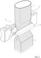
- Figures 3 and 4 show a condition in which each shaft 32 of the control device 29 of the first operative device 25* is in an angular position about the respective rotation axis E such that the respective half-shell 28 is in the first angular position and a condition in which each shaft 32 of the control device 29 of the second operative device 25** is in an angular position about the respective rotation axis E such that the respective half shell 28 is in the second angular position.
- figures 3 and 4 show a configuration of the half-shells 28 in which the respective first operative device 25* is in the rest configuration and a configuration of the half-shells 28 in which the respective second operative device 25** is in the active configuration.
- Each shaft 32 is configured to rotate about the respective rotation axis E so as to move the respective half-shell 28 between the respective first angular position and the respective second angular position.
- each shaft 32 is rotatable in a first rotation direction so as to move the half-shell 28 from the first angular position to the second angular position and is rotatable in a second rotation direction (opposed to the first rotation direction) so as to move the half-shell 28 from the second angular position to the first angular position.
- Each control device 29 comprises a lever mechanism 33 coupled to the shaft 32 and the half-shell 28. More in detail, the lever mechanism 33 is coupled to the shaft 32 and the main forming plate 30. The lever mechanism 33 is coupled exclusively to the shaft 32 and the main forming plate 30. Even more in detail, the lever mechanism 33 is not coupled to the lateral forming plates 31. Control devices 29 do not comprise any lever mechanism coupled to the lateral forming plates 31.
- the lever mechanism 33 is configured to actuate an angular movement of the respective main forming plate 30, in dependence of the angular movement of the respective shaft 32.
- the lever mechanism 33 comprises at least one coupling element 35, preferentially two coupling elements 35 spaced apart from one another and, fixed to the shaft 32 and at least one coupling bar 36, preferentially two coupling bars 36, hinged to one respective coupling element 35 and the respective main forming plate 30.
- each coupling bar 36 is hinged to the respective coupling element 35 about a (first) hinge axis R and is hinged to the respective main forming plate 30 about a (second) hinge axis H.
- each hinge axis R and the respective hinge axis H are parallel to one another.
- each hinge axis R and the respective hinge axis H are parallel to the respective rotation axis B and/or the respective rotation axis E.
- package forming apparatus may comprise an actuating device configured to control operation of each control device 29 so as to control the angular position of the respective half-shells 28.
- the actuating device is configured to control the angular position of shafts 32.
- the actuating device may be configured to control the respective angular position of shafts 32 in dependence of the respective position of the respective first operative group 26 and the respective second operative group 27 along the respective first advancement path and/or second advancement path.
- each operative device 25 comprises a sealing element 55 and a respective counter-sealing element 56 configured to transversally seal in cooperation with one another the tube 4.
- one of the first operative group 26 and the respective second operative group 27 comprises the sealing element 55 and the other one of the first operative group 26 and the respective second operative group 27 comprises the counter-sealing element 56.
- each operative device 25 comprises at least one cutting element configured to transversally cut the tube 4, preferentially after sealing of the tube 4 by means of the respective sealing element 55 and the respective counter-sealing element 56.
- packaging machine 1 produces packages 2 filled with the pourable product.
- the conveying device 11 advances the web 3 along the web advancement path P.
- the tube forming and sealing device 12 forms the tube 4 from the advancing web 3 and longitudinally seals the tube 4.
- the filling device 13 fills the tube 4 with the pourable product and the package forming apparatus 10 forms, transversally seals and transversally cuts the tube 4 so as to obtain packages 2.
- the operative devices 25 at least partially form, and preferentially transversally seal and transversally cut, the tube 4.
- each operative device 25 is cyclically controlled between the respective rest configuration and the respective active configuration.
- the respective first operative groups 26 and the respective second operative groups 27 advance along the respective advancement paths and are cyclically moved towards and away from one another so as to at least partially form, transversally seal and cut the tube 4 for forming packages 2.
- the partial forming of the tube 4 is controlled by the respective half-shells 28.
- the half shells 28 are moved from the respective first angular position to the respective second angular position, preferentially by controlling the angular position of the respective shaft 32.
Landscapes
- Engineering & Computer Science (AREA)
- Mechanical Engineering (AREA)
- Containers And Plastic Fillers For Packaging (AREA)
Applications Claiming Priority (1)
| Application Number | Priority Date | Filing Date | Title |
|---|---|---|---|
| IT102023000023082A IT202300023082A1 (it) | 2023-11-02 | 2023-11-02 | Apparato per formare pacchetti per una macchina di confezionamento e macchina di confezionamento per formare pacchetti riempiti con un prodotto versabile |
Publications (1)
| Publication Number | Publication Date |
|---|---|
| EP4549329A1 true EP4549329A1 (de) | 2025-05-07 |
Family
ID=89427181
Family Applications (1)
| Application Number | Title | Priority Date | Filing Date |
|---|---|---|---|
| EP24208815.1A Pending EP4549329A1 (de) | 2023-11-02 | 2024-10-25 | Verpackungsmaschine und verpackungsmaschine zum formen von mit einem fliessfähigen produkt gefüllten verpackungen |
Country Status (3)
| Country | Link |
|---|---|
| EP (1) | EP4549329A1 (de) |
| IT (1) | IT202300023082A1 (de) |
| WO (1) | WO2025093428A1 (de) |
Citations (2)
| Publication number | Priority date | Publication date | Assignee | Title |
|---|---|---|---|---|
| EP3318383A1 (de) * | 2016-11-03 | 2018-05-09 | G.D Societa' Per Azioni | Verfahren zur herstellung eines induktionsversiegelungskopfes für eine automatische maschine |
| EP3351478A1 (de) * | 2017-01-23 | 2018-07-25 | Tetra Laval Holdings & Finance S.A. | Formelement zur steuerung des volumens von verpackungen von giessbaren lebensmittelprodukten, die aus einem schlauch eines verpackungsmaterials geformt sind |
-
2023
- 2023-11-02 IT IT102023000023082A patent/IT202300023082A1/it unknown
-
2024
- 2024-10-25 WO PCT/EP2024/080171 patent/WO2025093428A1/en active Pending
- 2024-10-25 EP EP24208815.1A patent/EP4549329A1/de active Pending
Patent Citations (2)
| Publication number | Priority date | Publication date | Assignee | Title |
|---|---|---|---|---|
| EP3318383A1 (de) * | 2016-11-03 | 2018-05-09 | G.D Societa' Per Azioni | Verfahren zur herstellung eines induktionsversiegelungskopfes für eine automatische maschine |
| EP3351478A1 (de) * | 2017-01-23 | 2018-07-25 | Tetra Laval Holdings & Finance S.A. | Formelement zur steuerung des volumens von verpackungen von giessbaren lebensmittelprodukten, die aus einem schlauch eines verpackungsmaterials geformt sind |
Also Published As
| Publication number | Publication date |
|---|---|
| IT202300023082A1 (it) | 2025-05-02 |
| WO2025093428A1 (en) | 2025-05-08 |
Similar Documents
| Publication | Publication Date | Title |
|---|---|---|
| EP3725689B1 (de) | Verpackungsmaschine und verfahren zum herstellen von versiegelten verpackungen | |
| EP4032819B1 (de) | Vorschubförderer für eine faltvorrichtung, faltvorrichtung mit einem vorschubförderer und verpackungsmaschine mit einer faltvorrichtung | |
| EP4357253A1 (de) | Falzapparat und verpackungsmaschine mit einem falzapparat | |
| EP3943400B1 (de) | Verpackungsformungseinheit, verpackungsvorrichtung mit einer verpackungsformungseinheit und verfahren zur formung von verpackungen | |
| US20220177173A1 (en) | Packaging machine for producing sealed packages | |
| EP4549329A1 (de) | Verpackungsmaschine und verpackungsmaschine zum formen von mit einem fliessfähigen produkt gefüllten verpackungen | |
| EP4265533A1 (de) | Zuführförderer für eine falzvorrichtung, falzvorrichtung mit einem zuführförderer und verpackungsmaschine mit einer falzvorrichtung | |
| EP4410690B1 (de) | Verpackungsmaschine und verpackungsmaschine zum formen von mit einem fliessfähigen produkt gefüllten verpackungen | |
| EP4410691B1 (de) | Verpackungsmaschine und verpackungsmaschine zum formen von mit einem fliessfähigen produkt gefüllten verpackungen | |
| EP4474299A1 (de) | Verpackungsmaschine und vorrichtung zum herstellen von verpackungen | |
| EP4410692A1 (de) | Verpackungsmaschine und verpackungsmaschine zum formen von mit einem fliessfähigen produkt gefüllten verpackungen | |
| EP4588646A1 (de) | Vorrichtung zum anbringen eines siegelstreifens aus heisssiegelbarem material auf eine verpackungsmaterialbahn und verpackungsmaschine zum herstellen von siegelpackungen | |
| EP4410522A1 (de) | Verpackungsmaschine und verpackungsmaschine zum formen von mit einem fliessfähigen produkt gefüllten verpackungen | |
| EP4588648A1 (de) | Vorrichtung und verfahren zum siegeln einer verpackungsmaterialbahn, verpackungsmaschine zum siegeln einer verpackungsmaterialbahn | |
| EP4357254A1 (de) | Falzapparat und verpackungsmaschine mit einem falzapparat | |
| EP4410524A1 (de) | Verpackungsmaschine und verpackungsmaschine zum formen von mit einem fliessfähigen produkt gefüllten verpackungen | |
| EP4458689A1 (de) | Verpackungsmaschine für eine verpackungsmaschine, verpackungsmaschine zum formen von mit einem fliessfähigen produkt gefüllten verpackungen und verfahren zum formen von verpackungen | |
| EP4410523A1 (de) | Verpackungsmaschine und verpackungsmaschine zum formen von mit einem fliessfähigen produkt gefüllten verpackungen | |
| EP4410520A1 (de) | Verpackungsmaschine und verpackungsmaschine zum formen von mit einem fliessfähigen produkt gefüllten verpackungen |
Legal Events
| Date | Code | Title | Description |
|---|---|---|---|
| PUAI | Public reference made under article 153(3) epc to a published international application that has entered the european phase |
Free format text: ORIGINAL CODE: 0009012 |
|
| STAA | Information on the status of an ep patent application or granted ep patent |
Free format text: STATUS: THE APPLICATION HAS BEEN PUBLISHED |
|
| AK | Designated contracting states |
Kind code of ref document: A1 Designated state(s): AL AT BE BG CH CY CZ DE DK EE ES FI FR GB GR HR HU IE IS IT LI LT LU LV MC ME MK MT NL NO PL PT RO RS SE SI SK SM TR |
|
| STAA | Information on the status of an ep patent application or granted ep patent |
Free format text: STATUS: REQUEST FOR EXAMINATION WAS MADE |
|
| 17P | Request for examination filed |
Effective date: 20251107 |