EP4549347A1 - Système de transport avec un dispositif de production d'électricité - Google Patents
Système de transport avec un dispositif de production d'électricité Download PDFInfo
- Publication number
- EP4549347A1 EP4549347A1 EP23206930.2A EP23206930A EP4549347A1 EP 4549347 A1 EP4549347 A1 EP 4549347A1 EP 23206930 A EP23206930 A EP 23206930A EP 4549347 A1 EP4549347 A1 EP 4549347A1
- Authority
- EP
- European Patent Office
- Prior art keywords
- flywheel
- drive roll
- slide surface
- piece good
- conveyor system
- Prior art date
- Legal status (The legal status is an assumption and is not a legal conclusion. Google has not performed a legal analysis and makes no representation as to the accuracy of the status listed.)
- Pending
Links
Images

Classifications
-
- B—PERFORMING OPERATIONS; TRANSPORTING
- B65—CONVEYING; PACKING; STORING; HANDLING THIN OR FILAMENTARY MATERIAL
- B65G—TRANSPORT OR STORAGE DEVICES, e.g. CONVEYORS FOR LOADING OR TIPPING, SHOP CONVEYOR SYSTEMS OR PNEUMATIC TUBE CONVEYORS
- B65G13/00—Roller-ways
- B65G13/075—Braking means
-
- H—ELECTRICITY
- H02—GENERATION; CONVERSION OR DISTRIBUTION OF ELECTRIC POWER
- H02K—DYNAMO-ELECTRIC MACHINES
- H02K7/00—Arrangements for handling mechanical energy structurally associated with dynamo-electric machines, e.g. structural association with mechanical driving motors or auxiliary dynamo-electric machines
- H02K7/18—Structural association of electric generators with mechanical driving motors, e.g. with turbines
- H02K7/1807—Rotary generators
- H02K7/1853—Rotary generators driven by intermittent forces
-
- B—PERFORMING OPERATIONS; TRANSPORTING
- B65—CONVEYING; PACKING; STORING; HANDLING THIN OR FILAMENTARY MATERIAL
- B65G—TRANSPORT OR STORAGE DEVICES, e.g. CONVEYORS FOR LOADING OR TIPPING, SHOP CONVEYOR SYSTEMS OR PNEUMATIC TUBE CONVEYORS
- B65G11/00—Chutes
- B65G11/02—Chutes of straight form
- B65G11/023—Chutes of straight form for articles
-
- B—PERFORMING OPERATIONS; TRANSPORTING
- B65—CONVEYING; PACKING; STORING; HANDLING THIN OR FILAMENTARY MATERIAL
- B65G—TRANSPORT OR STORAGE DEVICES, e.g. CONVEYORS FOR LOADING OR TIPPING, SHOP CONVEYOR SYSTEMS OR PNEUMATIC TUBE CONVEYORS
- B65G11/00—Chutes
- B65G11/20—Auxiliary devices, e.g. for deflecting, controlling speed of, or agitating articles or solids
- B65G11/203—Auxiliary devices, e.g. for deflecting, controlling speed of, or agitating articles or solids for articles
-
- B—PERFORMING OPERATIONS; TRANSPORTING
- B65—CONVEYING; PACKING; STORING; HANDLING THIN OR FILAMENTARY MATERIAL
- B65G—TRANSPORT OR STORAGE DEVICES, e.g. CONVEYORS FOR LOADING OR TIPPING, SHOP CONVEYOR SYSTEMS OR PNEUMATIC TUBE CONVEYORS
- B65G13/00—Roller-ways
-
- B—PERFORMING OPERATIONS; TRANSPORTING
- B65—CONVEYING; PACKING; STORING; HANDLING THIN OR FILAMENTARY MATERIAL
- B65G—TRANSPORT OR STORAGE DEVICES, e.g. CONVEYORS FOR LOADING OR TIPPING, SHOP CONVEYOR SYSTEMS OR PNEUMATIC TUBE CONVEYORS
- B65G43/00—Control devices, e.g. for safety, warning or fault-correcting
-
- F—MECHANICAL ENGINEERING; LIGHTING; HEATING; WEAPONS; BLASTING
- F03—MACHINES OR ENGINES FOR LIQUIDS; WIND, SPRING, OR WEIGHT MOTORS; PRODUCING MECHANICAL POWER OR A REACTIVE PROPULSIVE THRUST, NOT OTHERWISE PROVIDED FOR
- F03G—SPRING, WEIGHT, INERTIA OR LIKE MOTORS; MECHANICAL-POWER PRODUCING DEVICES OR MECHANISMS, NOT OTHERWISE PROVIDED FOR OR USING ENERGY SOURCES NOT OTHERWISE PROVIDED FOR
- F03G3/00—Other motors, e.g. gravity or inertia motors
- F03G3/08—Other motors, e.g. gravity or inertia motors using flywheels
-
- F—MECHANICAL ENGINEERING; LIGHTING; HEATING; WEAPONS; BLASTING
- F03—MACHINES OR ENGINES FOR LIQUIDS; WIND, SPRING, OR WEIGHT MOTORS; PRODUCING MECHANICAL POWER OR A REACTIVE PROPULSIVE THRUST, NOT OTHERWISE PROVIDED FOR
- F03G—SPRING, WEIGHT, INERTIA OR LIKE MOTORS; MECHANICAL-POWER PRODUCING DEVICES OR MECHANISMS, NOT OTHERWISE PROVIDED FOR OR USING ENERGY SOURCES NOT OTHERWISE PROVIDED FOR
- F03G7/00—Mechanical-power-producing mechanisms, not otherwise provided for or using energy sources not otherwise provided for
- F03G7/08—Mechanical-power-producing mechanisms, not otherwise provided for or using energy sources not otherwise provided for recovering energy derived from swinging, rolling, pitching or like movements, e.g. from the vibrations of a machine
-
- H—ELECTRICITY
- H02—GENERATION; CONVERSION OR DISTRIBUTION OF ELECTRIC POWER
- H02J—ELECTRIC POWER NETWORKS; CIRCUIT ARRANGEMENTS OR SYSTEMS FOR SUPPLYING OR DISTRIBUTING ELECTRIC POWER; SYSTEMS FOR STORING ELECTRIC ENERGY
- H02J15/00—Systems for storing electric energy specially adapted for power networks
- H02J15/30—Systems for storing electric energy specially adapted for power networks using storage of inertial or mechanical energy, e.g. using flywheels
Definitions
- the invention relates to a conveyor system with a chute and a device for generating electricity, wherein the chute comprises a slide surface which is configured to transport a piece good by sliding down from a starting point to an end point arranged in the horizontal direction lower than the starting point.
- Conveyor systems are regularly used as conveying equipment for the gentle transport or forwarding of piece good in logistics, warehouses, or factories. If a difference in height is to be overcome during transport or forwarding, chutes are used over which the piece good slides down from a higher starting point to a lower end point. The focus is on the economical, safe, and gentle transport of piece good from incoming goods to outgoing goods.
- the chute is a drive-free conveying element that is used for space-saving, vertical transport.
- the piece good is moved by gravity only. The weight of the piece good is thus converted into kinetic energy with the help of the chute. When it reaches the end of the chute, the piece good bounces and the kinetic energy is abruptly lost.
- a conveyor system with a chute and a device for generating electricity comprises a slide surface which is configured to transport a piece good by sliding down from a starting point to an end point arranged in the horizontal direction lower than the starting point, and the device for generating electricity comprises at least one rotatable drive roll arranged in a plane of the slide surface and an electrical generator comprising a flywheel connectable with the at least one rotatable drive roll, wherein in an active state the at least one drive roll is connected with the flywheel and in an inactive state the at least one drive roll is disconnected from the flywheel.
- the slide surface can be especially a flat and/or planar surface.
- the slide surface can be especially a part of a roller conveyor. In this case the slide surface comprises rolls to transport the piece good.
- flywheel is understood especially as a mechanical device which uses the conservation of angular momentum to store rotational energy; a form of kinetic energy proportional to the product of its moment of inertia and the square of its rotational speed.
- the flywheel's moment of inertia is constant, for example a flywheel with fixed mass and second moment of area revolving about some fixed axis, then the stored rotational energy is directly associated with the square of its rotational speed.
- electrical generator is understood especially as a device that converts motion-based power, in particular potential and kinetic energy, into electric power for use in an external circuit.
- the sustained rotation of the flywheel allows the electrical generator to operate more efficiently and to generate electricity for a longer period of time.
- the drive roll is arranged into the slide surface in the same plane, so that a down sliding piece good slides over the drive roll.
- the drive roll In the active state the drive roll in connected with the flywheel that is connected with the electrical generator so that the down sliding piece good causes to drive roll to rotate.
- the rotating drive roll drives the flywheel which is connected with the generator that generates electricity by the movement of the flywheel.
- the flywheel and the drive roll are disconnected from each other so that the flywheel can continue to rotate freely without a stationary drive roll that slows the flywheel.
- chutes are in particular divided into spiral chutes, transfer chutes, bin chutes, buffer end points, small sort end points, and/or gravity roller chutes.
- the drive roller can be integrated in particular in any type of chute.
- the slide surface comprises a plurality of rolls.
- the plurality of rolls forms a gravity roller conveyor that is used as a whole chute for horizontal transport of piece good under a slight incline.
- the gravity roller conveyor can especially be used in addition to conventional chutes and end points as feeding or discharging elements.
- At the end of a transport line they can also serve as a buffer line.
- some of the plurality of rolls can be combined to build a plurality of drive rolls. The more rolls are coupled to the flywheel as drive rolls, the more kinetic energy can drive the flywheel and can consequently be converted into electrical energy. The efficiency of the device for generating electricity can thus be increased overall.
- the electrical generator comprises a dynamo or an alternator.
- a dynamo is an electrical generator that creates direct current using a commutator.
- the electric dynamo uses rotating coils of wire and magnetic fields to convert mechanical rotation into a pulsing direct electric current through Faraday's law of induction.
- a dynamo machine consists of a stationary structure, called the stator, which provides a constant magnetic field, and a set of rotating windings called the armature which turn within that field. Due to Faraday's law of induction, the motion of the wire within the magnetic field creates an electromotive force, which pushes on the electrons in the metal, creating an electric current in the wire.
- the constant magnetic field may be provided by one or more permanent magnets; larger machines have the constant magnetic field provided by one or more electromagnets, which are usually called field coils.
- An alternator is an electrical generator that converts mechanical energy to electrical energy in the form of alternating current.
- alternators especially use a rotating magnetic field with a stationary armature.
- a linear alternator or a rotating armature with a stationary magnetic field is used.
- a conductor moving relative to a magnetic field develops an electromotive force in it.
- This electromotive force reverses its polarity when it moves under magnetic poles of opposite polarity.
- a rotating magnet called the rotor turns within a stationary set of conductors wound in coils on an iron core, called the stator. The field cuts across the conductors, generating an induced electromotive force, as the mechanical input causes the rotor to turn.
- the flywheel is arranged in a plane different from the plane of the slide surface.
- the flywheel is arranged in horizontal direction under the slide surface and can be easily connected with the drive roll by lifting the flywheel or a connection element up.
- the flywheel and the at least one drive roll are connectable via a movable gearing system, especially a movable spur gearing system or a movable ring gearing system.
- the spur gearing is a type of gearbox with spur gears on parallel shafts.
- the motion between drive roll and gearbox is performed by a belt transmission or a gear.
- the motion between gearbox and flywheel is performed by gear.
- the simplest design is the single-stage spur gear unit with two shafts, on each of which a gear wheel is located.
- Multi-stage gears can be formed by adding more gears and intermediate shafts.
- Their advantages consist in their relatively simple design, since few moving parts are used, and the externally toothed spur gears are easy to manufacture.
- Ring gearing systems for example in planetary gears or worm or bevel gears, comprise wheels rotating on a revolving axis that orbit a central wheel similar to planets orbiting the sun. Ring gearing systems are characterized by a compact design with simultaneous high efficiency due to the transmission of several torques simultaneously.
- the spur gearing system or the ring gearing system can be moved, especially lifted up, so that a connection between the gearing system and the drive roll can be built. Once the gearing system and the drive roll are in touch with each other, the rotation of the drive roll drives the gearing system that drives the flywheel.
- the conveyor system further comprises a control unit for controlling the flywheel, wherein a rotation speed of the at least one rotatable drive roll is controllable via the flywheel in the active state.
- the speed and/or positioning of the piece good sliding down the chute can also be influenced by the at least one drive roll respectively by the flywheel.
- the control unit connects the drive roll with the flywheel especially in such a way that the piece good is slowed down and/or desired movement patterns and/or directions of movement are achieved.
- control unit comprises a programmable microcontroller, for example an chicken.
- a programmable microcontroller for example an chicken.
- “Arduino” is an Italian open-source hardware and software company, project, and user community that designs and manufactures single-board microcontrollers and microcontroller kits for building digital devices. Its hardware products are licensed under a CC BY-SA license, while the software is licensed under the GNU Lesser General Public License (LGPL) or the GNU General Public License (GPL), permitting the manufacture of chicken boards and software distribution by anyone.
- LGPL GNU Lesser General Public License
- GPL GNU General Public License
- the boards are equipped with sets of digital and analog input/output (I/O) pins that may be interfaced to various expansion boards ('shields') or breadboards (for prototyping) and other circuits.
- the boards feature serial communications interfaces, including Universal Serial Bus (USB) on some models, which are also used for loading programs.
- the microcontrollers can be programmed using the C and C++ programming languages, using a standard API which is also known as the PC Programming Language, inspired by the Processing language, and used with a modified version of the Processing IDE.
- the PC project provides an integrated development environment (IDE) and a command line tool developed in Go.
- a method for generating electricity with a conveyor system with a chute and a device for generating electricity wherein the chute comprises a slide surface which is configured to transport a piece good by sliding down from a starting point to an end point arranged in the horizontal direction lower than the starting point and a monitoring unit configured to detect a piece good sliding down the slide surface
- the device for generating electricity comprises at least one rotatable drive roll arranged in a plane of the slide surface and an electrical generator comprising a flywheel connectable with the at least one rotatable drive roll, wherein in an active state the at least one drive roll is connected with the flywheel and in an inactive state the at least one drive roll is disconnected with the flywheel, is further provided.
- the method comprises the following steps:
- detecting can be understood as an active measurement, for example by camera or sensor, or as a passive recognizing, for example because a mechanism gets activated because of the piece good sliding down.
- connecting and “disconnecting” can be understood as an active connecting or disconnecting, for example by an electrical mechanism, or as being passively connected or disconnected, for example by a mechanical mechanism.
- the drive roll is connected with the flywheel only if a piece good slides down the chute respectively the slide surface.
- the down sliding piece good is crucial for the generation of electricity. But if no piece good slides down the slide surface, a connection between the not rotating drive roll and the flywheel is counterproductive, because a stationary drive roll slows down the flywheel. Therefore, the flywheel is disconnected when not in use and/or between two down sliding piece goods, so that the flywheel can continue to rotate without moving the drive roll.
- the method comprises further with the following method steps: controlling a rotation speed of the at least one drive roll via the flywheel.
- the speed and/or positioning of the piece good sliding down the chute can be controlled by the at least one drive roll connected the flywheel.
- the piece good can be slowed down and/or can be moved in a desired direction.
- the conveyor system described above is used in logistics for generating electricity with a piece good sliding down a chute.
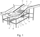
- Fig. 1 shows a conveyor system 1 of a preferred embodiment of the invention in a perspective view.
- the conveyor system 1 comprises a chute 2 for sliding down piece good 5 from a starting point A to a lower end point B.
- the piece good 5 moves because of gravity.
- the sliding surface 4 of the chute 2 comprises rolls 9.
- One of the rolls is a drive roll 6 that is connectable with a flywheel (not shown).
- the whole device for generating electricity 3 is shown in a simplified representation.
- the cute 2 further comprises a monitoring unit 11 for detecting whether a piece good 5 slides down the chute 2.
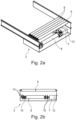
- the device for generating electricity 3 is shown in more detail in Fig. 2a and 2b .
- Fig. 2a shows the device for generating energy 3 of a preferred embodiment of the invention in a perspective view.
- the piece good 5 slides over the rolls 9 and also over the drive roll 6.
- the drive roll 6 is connectable with the flywheel 8 that is arranged under the drive roll 6.
- Fig 2a shows the inactive state.
- the drive roll 6 and the flywheel 8 are disconnected.
- the flywheel 8 is connected with an electrical generator 7.
- the drive roll 6 can be controlled via the control unit 12, which controls the flywheel, so that a down sliding piece good 5 can be slowed down or can be moved in a specific direction.
- Fig. 2b shows the device for generating electricity 3 in a frontal view. It is shown that the flywheel 8 with its gearing systems 10 can be easily connected with the drive roll 6 by lifting the gearing systems 10 up so that the gearing systems 10 that drive the flywheel touch the drive roll 6. If a piece good 5 slides down the sliding surface 4 the drive roll 6 will rotate and drive the gearing systems 10 which drive the flywheel 8.
- the flywheel 8 is designed to rotate with high efficiency and drives the electrical generator 7 to produce electric energy. The kinetic energy of the down sliding piece good 5 can thus be transformed into electric energy.
- Fig. 3 shows the method of producing electricity in a flow chart.
- the sliding surface is monitored. If a down sliding piece good 5 is detected or expected because of process data, the drive roll will be connected with the flywheel so that the rotating drive roll can drive the flywheel.
- the device for generating electricity 3 is then in active state. If no down sliding piece good 5 is detected or expected, for example between two down sliding piece goods 5, the drive roll 6 will be disconnected from the flywheel 8.
- the device for generating electricity 3 is then in inactive state and the flywheel 8 can freely rotate without being slowed down by the stationary drive roll 6. In this way the flywheel 8 is only connected with the drive roll in situations in which the drive roll will be actually driven so that the flywheel 8 can rotate and perform with an increased efficiency.
Landscapes
- Engineering & Computer Science (AREA)
- Mechanical Engineering (AREA)
- Chemical & Material Sciences (AREA)
- Combustion & Propulsion (AREA)
- Power Engineering (AREA)
- General Engineering & Computer Science (AREA)
- Control Of Conveyors (AREA)
- Rollers For Roller Conveyors For Transfer (AREA)
Priority Applications (3)
| Application Number | Priority Date | Filing Date | Title |
|---|---|---|---|
| EP23206930.2A EP4549347A1 (fr) | 2023-10-31 | 2023-10-31 | Système de transport avec un dispositif de production d'électricité |
| US18/929,983 US20250141306A1 (en) | 2023-10-31 | 2024-10-29 | Conveyor system with a device for generating electricity |
| CN202411527015.3A CN119911593A (zh) | 2023-10-31 | 2024-10-30 | 具有用于发电的装置的传送机系统 |
Applications Claiming Priority (1)
| Application Number | Priority Date | Filing Date | Title |
|---|---|---|---|
| EP23206930.2A EP4549347A1 (fr) | 2023-10-31 | 2023-10-31 | Système de transport avec un dispositif de production d'électricité |
Publications (1)
| Publication Number | Publication Date |
|---|---|
| EP4549347A1 true EP4549347A1 (fr) | 2025-05-07 |
Family
ID=88647549
Family Applications (1)
| Application Number | Title | Priority Date | Filing Date |
|---|---|---|---|
| EP23206930.2A Pending EP4549347A1 (fr) | 2023-10-31 | 2023-10-31 | Système de transport avec un dispositif de production d'électricité |
Country Status (3)
| Country | Link |
|---|---|
| US (1) | US20250141306A1 (fr) |
| EP (1) | EP4549347A1 (fr) |
| CN (1) | CN119911593A (fr) |
Families Citing this family (1)
| Publication number | Priority date | Publication date | Assignee | Title |
|---|---|---|---|---|
| US20250026571A1 (en) * | 2023-07-19 | 2025-01-23 | Intelligrated Headquarters, Llc | Energy reuse systems and methods |
Citations (7)
| Publication number | Priority date | Publication date | Assignee | Title |
|---|---|---|---|---|
| JPS5121665A (ja) * | 1974-08-16 | 1976-02-20 | Hitachi Ltd | Kaiseiseidoshikiidotaisoonboshisochi |
| JPH1151095A (ja) * | 1997-08-06 | 1999-02-23 | Tsubakimoto Chain Co | 回転体制動装置 |
| US5970712A (en) * | 1995-12-04 | 1999-10-26 | Stein; Allan Patrick | Combined material conveyor and electrical power generating system |
| US20170087728A1 (en) * | 2014-03-17 | 2017-03-30 | Grabit, Inc. | Electroadhesive gripping system with smart brake and metering |
| EP3480140A1 (fr) * | 2017-10-31 | 2019-05-08 | Günther Zimmer | Système de transport de pièces à usiner au moyen des roues transporteuses ou des rouleaux transporteurs pouvant être freinés |
| EP3629469A1 (fr) * | 2018-09-28 | 2020-04-01 | Siemens Aktiengesellschaft | Dispositif de transport à courroie ainsi que procédé de maintien d'une courroie d'un dispositif de transport à courroie |
| JP2023110202A (ja) * | 2022-01-28 | 2023-08-09 | トヨタ自動車株式会社 | ローラコンベア装置 |
-
2023
- 2023-10-31 EP EP23206930.2A patent/EP4549347A1/fr active Pending
-
2024
- 2024-10-29 US US18/929,983 patent/US20250141306A1/en active Pending
- 2024-10-30 CN CN202411527015.3A patent/CN119911593A/zh active Pending
Patent Citations (7)
| Publication number | Priority date | Publication date | Assignee | Title |
|---|---|---|---|---|
| JPS5121665A (ja) * | 1974-08-16 | 1976-02-20 | Hitachi Ltd | Kaiseiseidoshikiidotaisoonboshisochi |
| US5970712A (en) * | 1995-12-04 | 1999-10-26 | Stein; Allan Patrick | Combined material conveyor and electrical power generating system |
| JPH1151095A (ja) * | 1997-08-06 | 1999-02-23 | Tsubakimoto Chain Co | 回転体制動装置 |
| US20170087728A1 (en) * | 2014-03-17 | 2017-03-30 | Grabit, Inc. | Electroadhesive gripping system with smart brake and metering |
| EP3480140A1 (fr) * | 2017-10-31 | 2019-05-08 | Günther Zimmer | Système de transport de pièces à usiner au moyen des roues transporteuses ou des rouleaux transporteurs pouvant être freinés |
| EP3629469A1 (fr) * | 2018-09-28 | 2020-04-01 | Siemens Aktiengesellschaft | Dispositif de transport à courroie ainsi que procédé de maintien d'une courroie d'un dispositif de transport à courroie |
| JP2023110202A (ja) * | 2022-01-28 | 2023-08-09 | トヨタ自動車株式会社 | ローラコンベア装置 |
Also Published As
| Publication number | Publication date |
|---|---|
| CN119911593A (zh) | 2025-05-02 |
| US20250141306A1 (en) | 2025-05-01 |
Similar Documents
| Publication | Publication Date | Title |
|---|---|---|
| US20250141306A1 (en) | Conveyor system with a device for generating electricity | |
| KR101616569B1 (ko) | 압전효과와 전자기유도효과를 동시에 가지는 자가발전장치 | |
| WO1994026018A1 (fr) | Moto-generateur utilisant des aimants permanents | |
| EP3378145B1 (fr) | Générateur électrique à caractéristique d'évitement de résistance rotative | |
| US20140287875A1 (en) | Stationary Exercise Equipment Power Generator | |
| EP2823552A2 (fr) | Moteur a engrenage magnétique | |
| KR101758315B1 (ko) | 자이로스코프를 이용한 자가발전장치 | |
| US20060232068A1 (en) | Self powered electrical system | |
| JP2016025700A (ja) | 磁気ねじアクチュエータ | |
| CN109494890A (zh) | 一种基于磁耦合谐振的无芯电机及其控制方法 | |
| US9692275B2 (en) | Alternative energy generator | |
| CN106743448B (zh) | 一种软磁铁氧体产品分拣过渡装置 | |
| KR20200060263A (ko) | 발전 시스템 | |
| CN109927973A (zh) | 一种用于磁芯的自动排版装箱装置 | |
| CN108986330A (zh) | 一种家庭工具共享的存储控制系统及控制方法 | |
| AU2011382448B2 (en) | Magnetic power generation | |
| JP2003319625A (ja) | 複数のステーターを含むステップモーター | |
| Anto et al. | Sliding gate opener system with smartphone control using bluetooth connection | |
| CN219420624U (zh) | 一种应用于旋转柜的无刷电机的驱动控制电路及旋转柜 | |
| CN108217150A (zh) | 一种烘干机的新型送料装置 | |
| KR20060091038A (ko) | 회전 가속장치 및 이를 이용한 전력 생산/배분방법 | |
| CN214325563U (zh) | 一种智能打码生产线 | |
| Quoc Tien Thang | Motion Control System With Practice-Based Implementation | |
| Kicklighter | Design and Development of a Sensor/Actuator Module to Enhance Programmable Logic Controller (PLC) Laboratory Activities | |
| Behera et al. | Remote Control of BLDC Motor |
Legal Events
| Date | Code | Title | Description |
|---|---|---|---|
| PUAI | Public reference made under article 153(3) epc to a published international application that has entered the european phase |
Free format text: ORIGINAL CODE: 0009012 |
|
| STAA | Information on the status of an ep patent application or granted ep patent |
Free format text: STATUS: THE APPLICATION HAS BEEN PUBLISHED |
|
| STAA | Information on the status of an ep patent application or granted ep patent |
Free format text: STATUS: REQUEST FOR EXAMINATION WAS MADE |
|
| AK | Designated contracting states |
Kind code of ref document: A1 Designated state(s): AL AT BE BG CH CY CZ DE DK EE ES FI FR GB GR HR HU IE IS IT LI LT LU LV MC ME MK MT NL NO PL PT RO RS SE SI SK SM TR |
|
| 17P | Request for examination filed |
Effective date: 20250409 |