EP4549356A1 - Sicherheitssystem für aufzug - Google Patents
Sicherheitssystem für aufzug Download PDFInfo
- Publication number
- EP4549356A1 EP4549356A1 EP23306898.0A EP23306898A EP4549356A1 EP 4549356 A1 EP4549356 A1 EP 4549356A1 EP 23306898 A EP23306898 A EP 23306898A EP 4549356 A1 EP4549356 A1 EP 4549356A1
- Authority
- EP
- European Patent Office
- Prior art keywords
- sensors
- controller
- hoistway
- elevator
- landing
- Prior art date
- Legal status (The legal status is an assumption and is not a legal conclusion. Google has not performed a legal analysis and makes no representation as to the accuracy of the status listed.)
- Pending
Links
Images



Classifications
-
- B—PERFORMING OPERATIONS; TRANSPORTING
- B66—HOISTING; LIFTING; HAULING
- B66B—ELEVATORS; ESCALATORS OR MOVING WALKWAYS
- B66B5/00—Applications of checking, fault-correcting, or safety devices in elevators
- B66B5/0043—Devices enhancing safety during maintenance
- B66B5/005—Safety of maintenance personnel
-
- B—PERFORMING OPERATIONS; TRANSPORTING
- B66—HOISTING; LIFTING; HAULING
- B66B—ELEVATORS; ESCALATORS OR MOVING WALKWAYS
- B66B5/00—Applications of checking, fault-correcting, or safety devices in elevators
- B66B5/0043—Devices enhancing safety during maintenance
- B66B5/005—Safety of maintenance personnel
- B66B5/0056—Safety of maintenance personnel by preventing crushing
- B66B5/0062—Safety of maintenance personnel by preventing crushing by devices, being operable or not, mounted on the elevator car
-
- B—PERFORMING OPERATIONS; TRANSPORTING
- B66—HOISTING; LIFTING; HAULING
- B66B—ELEVATORS; ESCALATORS OR MOVING WALKWAYS
- B66B13/00—Doors, gates, or other apparatus controlling access to, or exit from, cages or lift well landings
- B66B13/22—Operation of door or gate contacts
-
- B—PERFORMING OPERATIONS; TRANSPORTING
- B66—HOISTING; LIFTING; HAULING
- B66B—ELEVATORS; ESCALATORS OR MOVING WALKWAYS
- B66B5/00—Applications of checking, fault-correcting, or safety devices in elevators
- B66B5/0043—Devices enhancing safety during maintenance
- B66B5/005—Safety of maintenance personnel
- B66B5/0081—Safety of maintenance personnel by preventing falling by means of safety fences or handrails, being operable or not, mounted on top of the elevator car
-
- B—PERFORMING OPERATIONS; TRANSPORTING
- B66—HOISTING; LIFTING; HAULING
- B66B—ELEVATORS; ESCALATORS OR MOVING WALKWAYS
- B66B5/00—Applications of checking, fault-correcting, or safety devices in elevators
- B66B5/0087—Devices facilitating maintenance, repair or inspection tasks
-
- B—PERFORMING OPERATIONS; TRANSPORTING
- B66—HOISTING; LIFTING; HAULING
- B66B—ELEVATORS; ESCALATORS OR MOVING WALKWAYS
- B66B2201/00—Aspects of control systems of elevators
- B66B2201/40—Details of the change of control mode
- B66B2201/46—Switches or switchgear
Definitions
- the present disclosure relates to systems and methods for ensuring the safety of service personnel while accessing an elevator hoistway.
- a safety system for an elevator system comprising a hoistway, a plurality of landing doors located on respective landings and an elevator car provided in the hoistway.
- the plurality of landing doors are configured to provide access to the hoistway.
- the safety system comprises a plurality of sensors and a controller. Each of the plurality of sensors is configured to produce an override signal when a landing door to which the sensor is connected is opened by a manual override.
- the controller is configured to instruct the elevator system to automatically enter a special operating mode when the override signal is received from one of the sensors.
- the controller automatically instructs the elevator system to enter a special operating mode as an additional safety measure. By making this process automatic, it reduces the likelihood of injury occurring to service personnel when performing service procedures such as inspections or maintenance on elevator systems.
- the safety system may operate independently of other controls within the elevator system such that it can be provided as a standalone system.
- the safety system may be retrofitted into existing elevator systems and buildings, providing a cost effective and environmentally friendly way of improving the safety of service personnel.
- the plurality of sensors are connected to the controller by a wireless connection.
- the plurality of sensors are connected to the controller by a wired connection.
- the plurality of sensors could be connected to the controller in any conceivable way such that they can communicate with the controller. In different applications, different connection methods may be applied.
- the plurality of sensors do not produce the override signal when the landing door to which each sensor is connected is opened in response to an elevator car arriving at the landing door.
- the plurality of sensors are configured such that no override signal is produced when a landing door is opened in response to the elevator car arriving at that landing.
- each of the plurality of sensors is configured to be connected to a landing door of a respective landing.
- the plurality of sensors are connected in series.
- each of the plurality of sensors comprises a switch.
- each of the plurality of sensors is configured to produce an override signal in response to being activated by a key.
- each of the plurality of sensors comprises a switch comprising an electrical contact which is opened when the landing door to which the sensor is connected is opened by a manual override.
- the special operating mode is a service mode.
- one or more of the plurality of sensors is configured to produce an override signal in response to being activated by a key, optionally wherein the key is configured to allow a landing door to be opened by a manual override when inserted into a lock.
- an elevator system comprising a hoistway; an elevator car disposed in the hoistway; a plurality of landing doors each located at respective landings and configured to provide access to the hoistway, the elevator car being adapted to travel to the respective landings.
- the elevator system further comprises the safety system for an elevator system as described above.
- Each of the one or more sensors is connected to a respective one of the landing doors.
- the elevator system when in the special operating mode, is configured to deploy a safety brake and/or a safety barrier, optionally an upper balustrade on the elevator car.
- the elevator car when in the special operating mode, the elevator car is unable to move.
- a method of operating a safety system for an elevator system comprising: a hoistway, a plurality of landing doors located on respective landings, and an elevator car provided in the hoistway.
- the plurality of landing doors are configured to provide access to the hoistway.
- the safety system comprises a plurality of sensors each connected to a respective landing door and a controller.
- the method comprises opening a landing door by manual override; in response to the opening the landing door by manual override, the sensor connected to the landing door producing an override signal; and in response to the controller receiving the override signal, the controller instructing the elevator system to automatically enter a special operating mode.
- the method comprises the elevator system deploying a safety brake and/or a safety barrier, optionally an upper balustrade on the elevator car, on entering the special operating mode.
- a computer program product for a controller of a safety system as described above, or an elevator system as described above.
- the computer program product includes instructions that, when executed by a processor, cause the controller to perform operations comprising: in response to receiving the override signal from one of the plurality of sensors, instructing the elevator system to automatically enter a special operating mode.
- the elevator system comprises: a hoistway, a plurality of landing doors located on respective landings, and an elevator car provided in the hoistway.
- the plurality of landing doors are configured to provide access to the hoistway.
- the method comprises: connecting a respective sensor to each of the plurality of landing doors, each sensor being configured to produce an override signal in response to the landing door to which it is connected being opened by a manual override; and connecting the sensors to a controller, the controller being configured to cause the elevator system to automatically enter a special operating mode in response to receiving the override signal from the one of the sensors.
- FIG. 1 shows an elevator system 100 comprising an elevator car 102 in a hoistway 104.
- the elevator car 102 is configured to move up and down the hoistway 104 to transport passengers between the different landings 106a-106f in a building (not shown).
- a building typically includes a number of different floors and that each floor may have a landing from which the hoistway may be accessed.
- the elevator system 100 may comprise other standard components including but not limited to drive means, tension members, a counterweight, a power source and a control panel.
- the elevator system 100 comprises a plurality of landing doors 112.
- Each landing door 112a, 112b, 112c, 112d, 112e, 112f in the elevator system 100 is located on a different respective landing 106a-106f.
- the plurality of landing doors 112a-112f provide access to the hoistway 104 when open. When a landing door 112 on a landing is closed, no access to the hoistway 104 is possible from that respective landing.
- the elevator car 102 is also accessible via a landing door 112f when the elevator car 102 is located at that respective landing 106f and when both an elevator car door (not shown) and the landing door 112f are open.
- the elevator system 100 comprises a safety system 105.
- the safety system 105 is used to ensure the safety of service personnel when attempting to enter the hoistway 104 to perform services procedures such as maintenance or inspection on the elevator car 102 or hoistway 104.
- service personnel are personnel charged with carrying out service actions on an elevator system. They are distinct from non-service personnel only in that they perform actions on an elevator system beyond what would be considered "normal use".
- the actions which may be performed by service personnel include, but are not limited to, inspection and/or maintenance of the elevator system.
- the safety system 105 comprises two or more sensors 120.
- the sensors 120 can produce an output (referred to as an override signal) in response to an event occurring.
- the event indicates that a landing door to which the sensor is connected has been opened by a manual override.
- the two or more sensors 120 and the controller 110 can be connected to form a safety chain 122.
- An output from two or more of the sensors 120 can be transmitted to the controller 110 via the safety chain 122.
- the two of the sensors 120 produces the override signal, it is transmitted to the controller 110 via the safety chain 122.
- the sensors 120 are connected to each other. In such examples, the sensors 120 may be connected via a wired electrical connection. In such examples, the sensors 120 may be connected in series.
- the sensors 120 are connected to the controller 110 via a wired electrical connection. In other examples, the sensors 120 are connected to the controller 110 via a wireless connection.
- the override signal in some examples comprises a change in the normal output from the sensors 120 to the controller 110 via the safety chain 122.
- the normal output from the sensors 120 may be a positive signal.
- the positive signal may be the flow of electric current.
- the positive signal may be a constant stream of data sent wirelessly.
- the override signal may comprise the electric current no longer flowing, or the constant stream of data sent wirelessly being interrupted.
- the normal output from the sensors 120 may be a negative signal.
- the negative signal may be lack of flow of electric current, or the lack of data sent wirelessly.
- the override signal may comprise the flow of electric current a stream of data being sent wirelessly.
- FIG 2 is a schematic illustration of a part of the elevator system 100 seen in Figure 1 .
- the sensors 120 are connected to the plurality of landing doors 112.
- each sensor 120a is connected to a single landing door 112a.
- the sensors 120 may be respectively situated adjacent to the plurality of landing doors 112 such that each landing door 112a is adjacent to a sensor 120a.
- the sensors 120 are configured to produce the override signal to be received by the controller 110 when any of the plurality of landing doors 112 to which they are connected are opened by service personnel or when they are opened by a manual override.
- the landing door 112a may be opened by service personnel in order to gain access to the hoistway 104 and/or to the exterior of the elevator car 102 for service procedures such as maintenance and/or inspection when the elevator car 102 is situated at one of the other landing doors in the plurality of landing doors 112, or when the elevator car 102 is not situated at any of the plurality of landing doors 112.
- the sensors 120 are configured to not produce the override signal in response to any of the plurality of landing doors 112 being opened in what is considered to be a "conventional" way.
- the "conventional" way is considered to be the landing doors 120 opening at a similar time to the elevator car doors following the arrival of the elevator car 102 at the landing at which the landing doors 120 are located.
- the two or more sensors 120 each comprise a switch.
- the switch may be moved from an open to a closed position by the landing door 112a being opened by a manual override or, in other words, not in the conventional way.
- the switch may be moved from a closed to an open position by the landing door 112a being opened by a manual override or, in other words, not in the conventional way.
- the switch may cause the override signal to be produced in response to the landing door 112a being opened by a manual override or, in other words, not in the conventional way.
- the or each switch may comprise an electrical contact 116 which is opened or closed such that, when the contact 116 is closed, current may flow along the safety chain 122 and when the contact 116 is opened, no current may flow along the safety chain 122.
- the controller 110 may be configured to instruct the elevator system 100 to automatically enter a special operating mode when no current is received from the safety chain 122, for example when the electrical contact 116 of one sensor 120 has been opened indicating that a landing door has been opened by a manual override.
- service personnel may open the landing door 112a by a manual override with a key (not shown), which activates the sensor 120a and causes the sensor 120a to produce the override signal which is received by the controller 110.
- the key may be unusually or uniquely shaped.
- the key may have a blade with a triangular cross section along its longest axis.
- the sensor 120a may produce the override signal in response to the key being inserted into a lock 118, and the key subsequently being turned relative to the lock 118.
- the lock 118 may comprise or be part of the sensor 120a.
- the lock 118 may include an electrical contact 116 of the type described above such that turning the key in the lock 118 moves the electrical contact 116 from a closed position to an open position to stop current flowing through the safety chain 122 (in other words, to produce an override signal).
- the lock 118 may be situated adjacent to the landing door 112a. In any example, a lock 118 may be provided for each respective landing door 112.
- the landing door 112a is configured to be opened in response to the key being inserted into the lock 118, and turned relative to the lock 118.
- the landing door 112a may be opened in this way irrespective of the position of the elevator car 102 in the hoistway 104.
- the elevator system 100 permits the elevator car 102 to move freely through the hoistway 104 depending on landing calls etc.
- the controller 110 constantly monitors the safety chain 122 so as to receive the output from the sensors 120. In some examples, the controller 110 may monitor the electrical current flowing through the safety chain 122 or monitor the data wirelessly transmitted via the safety chain 122.
- the controller 110 When the controller 110 receives the override signal, which indicates that at least one of the plurality of landing doors 112 has been opened by a manual override or by service personnel, the controller 110 instructs the elevator system 100 to automatically enter a special operating mode.
- the special operating mode may be a service mode, an inspection mode, or an override mode.
- the controller 110 may immediately instruct the elevator system 100 to immediately enter the special operating mode following the receipt of the override signal from one of the sensors 120.
- the elevator system 100 when in the special operating mode, the elevator system 100 deploys additional safety mechanisms to ensure the safety of service personnel in the hoistway 104, near the plurality of landing doors 112 and in or on the elevator car 102.
- the elevator system 100 may deploy a safety brake (not shown) on the elevator car 102 to prevent the elevator car 102 from moving in the hoistway 104.
- the safety brake may prevent the elevator car 102 from moving and may not be overridden until the elevator system 100 re-enters the normal mode.
- the elevator system 100 may deploy additional safety rails or balustrades around the elevator car 102 to prevent service personnel or objects falling into the hoistway 104.
- the safety rail may not be removed or moved out of position until the elevator system 100 re-enters the normal mode.
- the elevator system 100 may deploy additional lighting systems and sound systems to alert people nearby and/or to assist the service personnel in carrying out their duties.
- the elevator system 100 may deploy further safety measures at the landing door 112 (or in the hoistway 104 adjacent said landing door 112) which is associated with the sensor in the plurality of sensors 120 which has produced the override signal. In other examples, safety measures may be deployed at all of the plurality of landing doors 112.
- the elevator system 100 When in the special operating mode, the elevator system 100 is in a safe state for the hoistway 104 to be accessed and for service procedures such as maintenance or inspection to be carried out.
- the controller 110 may also be configured to instruct the elevator system 100 to return to the normal mode. In some examples, the controller 110 may instruct the elevator system 100 to return to the normal mode in response to receiving a normal output from the sensors 120 which produced the override signal. In examples, the normal output may be received via the safety chain 122. In some examples, the normal output may be produced in response to the key being turned and removed from the lock 118, in some examples closing the electrical contact 116.
- the elevator system 100 may return to the normal mode following further instruction input (for example to the controller) by service personnel.
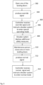
- Figure 3 depicts a method 300 of operating the safety system 105 of the elevator system 100 is also disclosed.
- the safety system 105 and elevator system 100 may comprise all of the features as described above.
- the method 300 comprises the service personnel opening one or more of the plurality of landing doors 112 by a manual override (step 302).
- the service personnel may open one of the plurality of landing doors 112 by inserting the key into the lock 118 and turning the key relative to the lock 118.
- the service personnel may open one of the landing doors 112 by pressing a button, or entering a code into a number pad.
- one of the sensors 120 In response to the service personnel opening one of the plurality of landing doors 112, one of the sensors 120 (the sensor connected to the respective landing door) produces the override signal (step 304).
- the override signal may be transmitted to the controller 110 via the safety chain 122.
- the controller 110 instructs the elevator system 100 to enter the special operating mode (step 306).
- the elevator system 100 may deploy additional safety measures at the plurality of landing doors 112 and/or in the hoistway 104 (step 308). In some examples, the elevator system 100 may deploy a safety brake, additional safety rails or balustrades, and lighting systems in the hoistway 104 or at the plurality of landing doors 112.
- the service personnel may close the one or more landing doors of the plurality of landing doors 112 that were previously open (step 310).
- the one or more landing doors may be closed by removing the key from the lock 118, by pressing a button, or by entering a code into a number pad.
- the senor 120 may produce the normal output rather than the override signal (step 312).
- the normal output may be received by the controller 110 via the safety chain 122.
- the controller 110 may instruct the elevator system 100 to enter the normal mode, or to revert to the normal operating mode from the special operating mode.
- FIG. 4 depicts a method 400 of modifying an elevator system.
- the elevator system comprises all of the conventional components of an elevator system, but does not comprise a safety system 105 which automatically instructs the elevator system to enter a special operating mode when service personnel attempts to access the hoistway 104.
- a safety system 105 may be retrofitted into an existing elevator system. Further, it does not require the controller 110 to measure or monitor the location of the elevator car 102 in the hoistway 104 in order to automatically enter a special operating mode of the elevator system 100.
- the method comprises connecting one or more sensors 120 to each of a plurality of landing doors 112 (step 402).
- the one or more sensors 120 may be placed adjacent to each of the landing doors 112.
- the one or more sensors 120 are configured to produce an override signal in response to service personnel opening one or more of the plurality of landing doors 112 by a manual override.
- the method further comprises connecting the sensors 120 together, for example in series, for example by a wired connection (step 404).
- the method further comprises connecting the one or more sensors 120 to a controller 110 (step 406).
- the controller 110 is configured to instruct the elevator system 100 to enter the special operating mode in response to receiving the override signal from the one or more sensors 120.
- the one or more sensors 120 and the controller 110 may be connected to form a safety chain 122.
- the controller 110 may be an existing controller of the elevator system 100 or may be an additional controller.
- the method further comprises connecting the controller 110 to the elevator system 100 (step 408).
- the elevator car may be used in a roped or ropeless elevator system, or another type of conveyance system.
Landscapes
- Maintenance And Inspection Apparatuses For Elevators (AREA)
Priority Applications (3)
| Application Number | Priority Date | Filing Date | Title |
|---|---|---|---|
| EP23306898.0A EP4549356A1 (de) | 2023-11-02 | 2023-11-02 | Sicherheitssystem für aufzug |
| US18/933,328 US20250145412A1 (en) | 2023-11-02 | 2024-10-31 | Elevator safety system |
| CN202411549152.7A CN119929614A (zh) | 2023-11-02 | 2024-11-01 | 电梯安全系统 |
Applications Claiming Priority (1)
| Application Number | Priority Date | Filing Date | Title |
|---|---|---|---|
| EP23306898.0A EP4549356A1 (de) | 2023-11-02 | 2023-11-02 | Sicherheitssystem für aufzug |
Publications (1)
| Publication Number | Publication Date |
|---|---|
| EP4549356A1 true EP4549356A1 (de) | 2025-05-07 |
Family
ID=88839776
Family Applications (1)
| Application Number | Title | Priority Date | Filing Date |
|---|---|---|---|
| EP23306898.0A Pending EP4549356A1 (de) | 2023-11-02 | 2023-11-02 | Sicherheitssystem für aufzug |
Country Status (3)
| Country | Link |
|---|---|
| US (1) | US20250145412A1 (de) |
| EP (1) | EP4549356A1 (de) |
| CN (1) | CN119929614A (de) |
Citations (2)
| Publication number | Priority date | Publication date | Assignee | Title |
|---|---|---|---|---|
| US20120031707A1 (en) * | 2009-04-23 | 2012-02-09 | Kone Corporation | Safety arrangement of an elevator |
| EP2623452A1 (de) * | 2010-10-01 | 2013-08-07 | Mitsubishi Electric Corporation | System zur umschaltung eines aufzugsbetriebsmodus |
-
2023
- 2023-11-02 EP EP23306898.0A patent/EP4549356A1/de active Pending
-
2024
- 2024-10-31 US US18/933,328 patent/US20250145412A1/en active Pending
- 2024-11-01 CN CN202411549152.7A patent/CN119929614A/zh active Pending
Patent Citations (2)
| Publication number | Priority date | Publication date | Assignee | Title |
|---|---|---|---|---|
| US20120031707A1 (en) * | 2009-04-23 | 2012-02-09 | Kone Corporation | Safety arrangement of an elevator |
| EP2623452A1 (de) * | 2010-10-01 | 2013-08-07 | Mitsubishi Electric Corporation | System zur umschaltung eines aufzugsbetriebsmodus |
Also Published As
| Publication number | Publication date |
|---|---|
| CN119929614A (zh) | 2025-05-06 |
| US20250145412A1 (en) | 2025-05-08 |
Similar Documents
| Publication | Publication Date | Title |
|---|---|---|
| AU2008340128B2 (en) | Circuit for resetting an elevator safety chain | |
| KR101481568B1 (ko) | 엘리베이터 안전 시스템 및 방법 | |
| US6364066B1 (en) | Remote rescue of trapped elevator passengers | |
| EP2671836B1 (de) | Sicherheitssteuervorrichtung für aufzüge | |
| US10947087B2 (en) | Elevator safety system and method of operating an elevator system | |
| CN112135787B (zh) | 安全切换系统以及用于在正常运行模式与检查运行模式之间切换电梯设备的方法 | |
| JP2001080836A (ja) | 昇降路の出入りにおける安全性確保の方法及びエレベータ装置 | |
| CN103917471A (zh) | 电梯安全控制装置 | |
| US20190389695A1 (en) | Elevator system | |
| EP1867594B1 (de) | Aufzugssystem und betriebssteuerungsverfahren dafür | |
| US20250145412A1 (en) | Elevator safety system | |
| JP4661022B2 (ja) | エレベータシステム及びその点検方法 | |
| JPH1017233A (ja) | エレベーターの非常時運転装置及び運転方法 | |
| EP4549362B1 (de) | Sicherheitssystem für aufzug, verfahren zum betreiben eines sicherheitssystems und ein computerprogrammprodukt zur steuerung eines sicherheitsystems | |
| JP6537539B2 (ja) | エレベーターの制御装置および制御方法 | |
| JP4255687B2 (ja) | エレベータの運転制御装置 | |
| JP6734822B2 (ja) | エレベーター装置 | |
| CN113508087A (zh) | 电梯系统 | |
| JP4536362B2 (ja) | エレベータ制御装置 | |
| KR101996496B1 (ko) | 엘리베이터 카 상부 진입운전 시스템 | |
| JP2007254037A (ja) | エレベータの運転制御装置 | |
| WO2025103924A1 (en) | An elevator installation and a method for accessing a roof of an elevator car | |
| JP2003312957A (ja) | エレベータ制御装置 | |
| HK1208429B (en) | Elevator having interlayer adjustment function | |
| HK1208429A1 (zh) | 带层间调整功能电梯 |
Legal Events
| Date | Code | Title | Description |
|---|---|---|---|
| PUAI | Public reference made under article 153(3) epc to a published international application that has entered the european phase |
Free format text: ORIGINAL CODE: 0009012 |
|
| STAA | Information on the status of an ep patent application or granted ep patent |
Free format text: STATUS: THE APPLICATION HAS BEEN PUBLISHED |
|
| AK | Designated contracting states |
Kind code of ref document: A1 Designated state(s): AL AT BE BG CH CY CZ DE DK EE ES FI FR GB GR HR HU IE IS IT LI LT LU LV MC ME MK MT NL NO PL PT RO RS SE SI SK SM TR |
|
| STAA | Information on the status of an ep patent application or granted ep patent |
Free format text: STATUS: REQUEST FOR EXAMINATION WAS MADE |
|
| 17P | Request for examination filed |
Effective date: 20251106 |
|
| STAA | Information on the status of an ep patent application or granted ep patent |
Free format text: STATUS: EXAMINATION IS IN PROGRESS |