EP4549406A1 - Un système de dessalement alimenté par les vagues - Google Patents
Un système de dessalement alimenté par les vagues Download PDFInfo
- Publication number
- EP4549406A1 EP4549406A1 EP23207463.3A EP23207463A EP4549406A1 EP 4549406 A1 EP4549406 A1 EP 4549406A1 EP 23207463 A EP23207463 A EP 23207463A EP 4549406 A1 EP4549406 A1 EP 4549406A1
- Authority
- EP
- European Patent Office
- Prior art keywords
- pump
- wave
- powered
- cylinder
- pressure
- Prior art date
- Legal status (The legal status is an assumption and is not a legal conclusion. Google has not performed a legal analysis and makes no representation as to the accuracy of the status listed.)
- Pending
Links
Images



Classifications
-
- B—PERFORMING OPERATIONS; TRANSPORTING
- B01—PHYSICAL OR CHEMICAL PROCESSES OR APPARATUS IN GENERAL
- B01D—SEPARATION
- B01D61/00—Processes of separation using semi-permeable membranes, e.g. dialysis, osmosis or ultrafiltration; Apparatus, accessories or auxiliary operations specially adapted therefor
- B01D61/02—Reverse osmosis; Hyperfiltration ; Nanofiltration
- B01D61/10—Accessories; Auxiliary operations
-
- C—CHEMISTRY; METALLURGY
- C02—TREATMENT OF WATER, WASTE WATER, SEWAGE, OR SLUDGE
- C02F—TREATMENT OF WATER, WASTE WATER, SEWAGE, OR SLUDGE
- C02F1/00—Treatment of water, waste water, or sewage
- C02F1/44—Treatment of water, waste water, or sewage by dialysis, osmosis or reverse osmosis
- C02F1/441—Treatment of water, waste water, or sewage by dialysis, osmosis or reverse osmosis by reverse osmosis
-
- F—MECHANICAL ENGINEERING; LIGHTING; HEATING; WEAPONS; BLASTING
- F03—MACHINES OR ENGINES FOR LIQUIDS; WIND, SPRING, OR WEIGHT MOTORS; PRODUCING MECHANICAL POWER OR A REACTIVE PROPULSIVE THRUST, NOT OTHERWISE PROVIDED FOR
- F03B—MACHINES OR ENGINES FOR LIQUIDS
- F03B13/00—Adaptations of machines or engines for special use; Combinations of machines or engines with driving or driven apparatus; Power stations or aggregates
- F03B13/12—Adaptations of machines or engines for special use; Combinations of machines or engines with driving or driven apparatus; Power stations or aggregates characterised by using wave or tide energy
- F03B13/14—Adaptations of machines or engines for special use; Combinations of machines or engines with driving or driven apparatus; Power stations or aggregates characterised by using wave or tide energy using wave energy
- F03B13/16—Adaptations of machines or engines for special use; Combinations of machines or engines with driving or driven apparatus; Power stations or aggregates characterised by using wave or tide energy using wave energy using the relative movement between a wave-operated member, i.e. a "wom" and another member, i.e. a reaction member or "rem"
- F03B13/20—Adaptations of machines or engines for special use; Combinations of machines or engines with driving or driven apparatus; Power stations or aggregates characterised by using wave or tide energy using wave energy using the relative movement between a wave-operated member, i.e. a "wom" and another member, i.e. a reaction member or "rem" wherein both members, i.e. wom and rem are movable relative to the sea bed or shore
-
- B—PERFORMING OPERATIONS; TRANSPORTING
- B01—PHYSICAL OR CHEMICAL PROCESSES OR APPARATUS IN GENERAL
- B01D—SEPARATION
- B01D2313/00—Details relating to membrane modules or apparatus
- B01D2313/24—Specific pressurizing or depressurizing means
-
- B—PERFORMING OPERATIONS; TRANSPORTING
- B01—PHYSICAL OR CHEMICAL PROCESSES OR APPARATUS IN GENERAL
- B01D—SEPARATION
- B01D2313/00—Details relating to membrane modules or apparatus
- B01D2313/24—Specific pressurizing or depressurizing means
- B01D2313/243—Pumps
-
- B—PERFORMING OPERATIONS; TRANSPORTING
- B01—PHYSICAL OR CHEMICAL PROCESSES OR APPARATUS IN GENERAL
- B01D—SEPARATION
- B01D2313/00—Details relating to membrane modules or apparatus
- B01D2313/24—Specific pressurizing or depressurizing means
- B01D2313/246—Energy recovery means
-
- B—PERFORMING OPERATIONS; TRANSPORTING
- B01—PHYSICAL OR CHEMICAL PROCESSES OR APPARATUS IN GENERAL
- B01D—SEPARATION
- B01D2313/00—Details relating to membrane modules or apparatus
- B01D2313/36—Energy sources
- B01D2313/367—Renewable energy sources, e.g. wind or solar sources
-
- B—PERFORMING OPERATIONS; TRANSPORTING
- B01—PHYSICAL OR CHEMICAL PROCESSES OR APPARATUS IN GENERAL
- B01D—SEPARATION
- B01D61/00—Processes of separation using semi-permeable membranes, e.g. dialysis, osmosis or ultrafiltration; Apparatus, accessories or auxiliary operations specially adapted therefor
- B01D61/02—Reverse osmosis; Hyperfiltration ; Nanofiltration
- B01D61/06—Energy recovery
-
- C—CHEMISTRY; METALLURGY
- C02—TREATMENT OF WATER, WASTE WATER, SEWAGE, OR SLUDGE
- C02F—TREATMENT OF WATER, WASTE WATER, SEWAGE, OR SLUDGE
- C02F2103/00—Nature of the water, waste water, sewage or sludge to be treated
- C02F2103/08—Seawater, e.g. for desalination
-
- F—MECHANICAL ENGINEERING; LIGHTING; HEATING; WEAPONS; BLASTING
- F03—MACHINES OR ENGINES FOR LIQUIDS; WIND, SPRING, OR WEIGHT MOTORS; PRODUCING MECHANICAL POWER OR A REACTIVE PROPULSIVE THRUST, NOT OTHERWISE PROVIDED FOR
- F03B—MACHINES OR ENGINES FOR LIQUIDS
- F03B13/00—Adaptations of machines or engines for special use; Combinations of machines or engines with driving or driven apparatus; Power stations or aggregates
- F03B13/12—Adaptations of machines or engines for special use; Combinations of machines or engines with driving or driven apparatus; Power stations or aggregates characterised by using wave or tide energy
- F03B13/14—Adaptations of machines or engines for special use; Combinations of machines or engines with driving or driven apparatus; Power stations or aggregates characterised by using wave or tide energy using wave energy
- F03B13/16—Adaptations of machines or engines for special use; Combinations of machines or engines with driving or driven apparatus; Power stations or aggregates characterised by using wave or tide energy using wave energy using the relative movement between a wave-operated member, i.e. a "wom" and another member, i.e. a reaction member or "rem"
- F03B13/18—Adaptations of machines or engines for special use; Combinations of machines or engines with driving or driven apparatus; Power stations or aggregates characterised by using wave or tide energy using wave energy using the relative movement between a wave-operated member, i.e. a "wom" and another member, i.e. a reaction member or "rem" where the other member, i.e. rem is fixed, at least at one point, with respect to the sea bed or shore
- F03B13/1845—Adaptations of machines or engines for special use; Combinations of machines or engines with driving or driven apparatus; Power stations or aggregates characterised by using wave or tide energy using wave energy using the relative movement between a wave-operated member, i.e. a "wom" and another member, i.e. a reaction member or "rem" where the other member, i.e. rem is fixed, at least at one point, with respect to the sea bed or shore and the wom slides relative to the rem
- F03B13/1875—Adaptations of machines or engines for special use; Combinations of machines or engines with driving or driven apparatus; Power stations or aggregates characterised by using wave or tide energy using wave energy using the relative movement between a wave-operated member, i.e. a "wom" and another member, i.e. a reaction member or "rem" where the other member, i.e. rem is fixed, at least at one point, with respect to the sea bed or shore and the wom slides relative to the rem and the wom is the piston or the cylinder in a pump
-
- F—MECHANICAL ENGINEERING; LIGHTING; HEATING; WEAPONS; BLASTING
- F04—POSITIVE - DISPLACEMENT MACHINES FOR LIQUIDS; PUMPS FOR LIQUIDS OR ELASTIC FLUIDS
- F04B—POSITIVE-DISPLACEMENT MACHINES FOR LIQUIDS; PUMPS
- F04B5/00—Machines or pumps with differential-surface pistons
- F04B5/02—Machines or pumps with differential-surface pistons with double-acting pistons
-
- F—MECHANICAL ENGINEERING; LIGHTING; HEATING; WEAPONS; BLASTING
- F04—POSITIVE - DISPLACEMENT MACHINES FOR LIQUIDS; PUMPS FOR LIQUIDS OR ELASTIC FLUIDS
- F04B—POSITIVE-DISPLACEMENT MACHINES FOR LIQUIDS; PUMPS
- F04B9/00—Piston machines or pumps characterised by the driving or driven means to or from their working members
- F04B9/08—Piston machines or pumps characterised by the driving or driven means to or from their working members the means being fluid
- F04B9/10—Piston machines or pumps characterised by the driving or driven means to or from their working members the means being fluid the fluid being liquid
- F04B9/103—Piston machines or pumps characterised by the driving or driven means to or from their working members the means being fluid the fluid being liquid having only one pumping chamber
- F04B9/105—Piston machines or pumps characterised by the driving or driven means to or from their working members the means being fluid the fluid being liquid having only one pumping chamber reciprocating movement of the pumping member being obtained by a double-acting liquid motor
-
- F—MECHANICAL ENGINEERING; LIGHTING; HEATING; WEAPONS; BLASTING
- F05—INDEXING SCHEMES RELATING TO ENGINES OR PUMPS IN VARIOUS SUBCLASSES OF CLASSES F01-F04
- F05B—INDEXING SCHEME RELATING TO WIND, SPRING, WEIGHT, INERTIA OR LIKE MOTORS, TO MACHINES OR ENGINES FOR LIQUIDS COVERED BY SUBCLASSES F03B, F03D AND F03G
- F05B2220/00—Application
- F05B2220/62—Application for desalination
-
- Y—GENERAL TAGGING OF NEW TECHNOLOGICAL DEVELOPMENTS; GENERAL TAGGING OF CROSS-SECTIONAL TECHNOLOGIES SPANNING OVER SEVERAL SECTIONS OF THE IPC; TECHNICAL SUBJECTS COVERED BY FORMER USPC CROSS-REFERENCE ART COLLECTIONS [XRACs] AND DIGESTS
- Y02—TECHNOLOGIES OR APPLICATIONS FOR MITIGATION OR ADAPTATION AGAINST CLIMATE CHANGE
- Y02A—TECHNOLOGIES FOR ADAPTATION TO CLIMATE CHANGE
- Y02A20/00—Water conservation; Efficient water supply; Efficient water use
- Y02A20/124—Water desalination
- Y02A20/131—Reverse-osmosis
Definitions
- the present disclosure relates to the field of desalinators. More particularly, the present disclosure relates to a wave-powered desalinator system.
- Osmosis The expression 'osmosis used in the context of this disclosure refers to but not limited to; osmosis is a net movement of a solution with less concentration through a membrane into a solution with a higher concentration. Only a few molecules of dissolved salts, organics, bacteria and pyrogens are allowed to pass through the semi-permeable membrane.
- Water covers 70 % of the earth's surface. Even though a large portion of the earth is covered by water, there is a severe scarcity of drinking water in most of countries across the world, as the majority of the water is in the form of saline sea water.
- the desalination technique is used to convert the saline seawater into usable water.
- Reverse osmosis is well known desalination technique conventionally used to obtain clean drinkable water.
- Reverse osmosis is the process in which a feed water like saline seawater is pressurised through the semi-permeable membrane. Water molecules that pass through the membrane are called as permeate water. Majority of salts, organics, bacteria and pyrogens are restricted to pass through the membrane and are discharged through the reject stream, which is called as brine stream.
- reverse osmosis RO desalination plants are installed on a land.
- the desalination rate of these land-based RO desalination plants is 35 % to 45 %.
- a pre-treatment needs to be applied to the seawater, to remove particulates, debris, microorganism, suspended solids and slit from the source seawater before reverse osmosis desalination.
- the pre-treatment includes the addition of various chemicals in the seawater. This pre-treatment process increases overall cost of desalination. For lower recovery, rates pre-treatment may not be required.
- these desalination plants are located far from the seashore, so the seawater needs to be pumped from offshore to the RO plant through pipes.
- the land-based RO plant includes a pump used to increase the pressure of the fluid supplied to RO membrane. But the pump consumes high electrical energy, which increases the cost of the desalination.
- Convention land-based RO plant comprises an energy recovery device/a pressure intensifier.
- Various types of energy recovery devices exist in the market.
- One of such well-known pressure intensifiers is a Clark pump.
- pressure intensifiers have complex construction, may not be suitable for larger commercial system. Further, it requires multiple steps for carrying out routine maintenance, making maintenance lengthy.
- An object of the present disclosure is to provide a wave-powered desalinator system.
- Another object of the present disclosure is to provide a wave-powered desalinator system that reduces pre-treatment efforts required for desalinating seawater.
- Yet another object of the present disclosure is to provide a wave-powered desalinator system that reduces overall energy consumption required for desalinating seawater.
- Still another object of the present disclosure is to provide a wave-powered desalinator system that operate efficiently under variable flow from seawater pump.
- Another object of the present disclosure is to provide a wave-powered pump that uses energy of sea waves for pumping water.
- Another object of the present disclosure is to provide a wave-powered pump that reduces energy consumption required for pumping water.
- Yet another object of the present disclosure is to provide a pressure intensifier for a desalinator system that has simple construction and requires less maintenance efforts.
- Still another object of the present disclosure is to provide a pressure intensifier for a desalinator system that allows controlling fresh water recovery rate.
- a wave-powered desalinator system for desalinating seawater.
- the wave-powered desalinator system comprises, at least a wave-powered pump, a pressure intensifier unit, a reverse osmosis (RO) membrane unit.
- RO reverse osmosis
- the pressure intensifier unit is connected downstream of the wave powered pump/s; the pressure intensifier unit is configured to increase the pressure of the water received from the wave powered pump/s.
- the reverse osmosis (RO) membrane unit is connected downstream of an outlet of the pressure intensifier unit.
- the RO membrane unit is configured to convert incoming high-pressure seawater into a desalinated water stream and high-pressure brine.
- the pressure intensifier unit is configured to utilize the high-pressure brine supplied by RO membrane unit to increase the pressure of seawater in the pressure intensifier unit and discharge a low-pressure brine.
- the wave-powered pump is configured to at least partially float on seawater and pump the seawater from pump inlet to pump outlet using the energy of waves of the seawater.
- the wave-powered pump/s are attached to a support structure by suitable connection means.
- the support structure is selected from a floating type support structure or a support structure fixed to seabed.
- a pre-filter unit is connected downstream of the wave-powered pump/s.
- the pre-filter unit is configured to filter water received from the wave-powered pump/s.
- the wave-powered pump is held in place by connecting it with the support structure.
- the pump comprises, a pump plunger connected to the support structure and the pump plunger comprises a pump outlet provided near an operative top end of the pump plunger.
- the pump comprises a pump barrel comprising a fluid inlet provided at an operative bottom end of the pump barrel and an operative top end of the pump barrel is slidably connected to the outer periphery of the pump plunger and configured to slide along length of the pump plunger.
- the pump plunger and the pump barrel are configured to form a pump cavity between the outer periphery of the pump plunger and the inner periphery of the pump barrel.
- a float is connected to the outer periphery of the pump barrel and configured to move vertically along with the pump barrel.
- the pump barrel comprises an inlet valve located near the fluid inlet submerged in the fluid, the inlet valve configured to allow entry of the fluid inside the pump cavity and prevent discharge of fluid from the fluid inlet.
- the pump plunger comprises an outlet valve located near the operative bottom end of the pump plunger; the outlet valve is configured to allow discharge of pumped water from the pump cavity towards the pump outlet.
- the pump comprises a filter screen at the fluid inlet and a self-cleaning mechanism configured to clean the filter screen.
- the self-cleaning mechanism comprises, a secondary float configured to move vertically relative to the float, at least a support member having one end connected to the secondary float, and a plurality of wiping means connected to other end of the support member.
- the wiping means projecting towards outer peripheral surface of filter screen and are configured to scrub and clean the filter screen during operative condition.
- the wiping means comprises plurality of rings with outer peripheral edge attached to the support member and inner peripheral edge configured to scrub the filter screen.
- the wiping means comprises plurality of scraper blades with one end of the scraper blade connected to the support member and another end configured to scrub the filter screen.
- the support member is selected from a rod or a pipe.
- the pressure intensifier unit comprises, a first pump cylinder and a second pump cylinder disposed co-axial with the first pump cylinder.
- the first pump cylinder and the second pump cylinder separated by a spacer.
- the pressure intensifier unit comprises a first piston configured to slide inside the first pump cylinder and a second pump piston is configured to slide inside the second pump cylinder.
- Each of the first pump cylinder and second pump cylinder comprises, a seawater inlet port configured to supply low-pressure seawater into the cylinders, a seawater outlet port configured to discharge high pressure seawater out of the cylinder, a brine inlet port configured to supply high-pressure brine into the cylinder, and a brine outlet port configured to discharge low pressure brine out of the cylinder.
- the pressure intensifier unit comprises, a tie rod is connecting the first side of the first piston with the first side of the second piston.
- the pressure intensifier unit comprises a first displacer rod is provided at the second side of the first piston and a second displacer rod provided at the second side of the second piston and the diameter of the first displacer rod and second displacer rod is greater than the diameter of the tie rod.
- a first bearing seal assembly and second a bearing seal assembly is disposed at first end of the first pump cylinder and the second pump cylinder.
- the first bearing seal assembly is configured to seal first end of the first pump cylinder and the tie rod
- the second bearing seal assembly is configured to seal first end of the second pump cylinder and the tie rod.
- a third bearing seal assembly and fourth bearing seal assembly is disposed at second end of the first pump cylinder and the second pump cylinder.
- the third bearing seal assembly is configured to seal second end of the first pump cylinder and the first displacer rod
- the fourth bearing seal assembly is configured to seal second end of the second pump cylinder and the second displacer rod.
- the first bearing seal assembly, the second bearing seal assembly, the third bearing seal assembly and the fourth bearing seal assembly are configured to be externally accessible.
- the first displacer rod and the second displacer rod are removably installed in the first pump cylinder and the second pump cylinder respectively.
- a wave-powered pump is disclosed.
- the wave-powered pump is used for pumping fluid using the motion of fluid waves.
- the wave-powered pump at least partially floating on fluid and held in place by connecting with a support structure.
- the pump comprises, a pump plunger connected to the support structure and the pump plunger comprises a pump outlet provided near an operative top end of the pump plunger.
- the pump comprises a pump barrel comprising a fluid inlet provided at an operative bottom end of the pump barrel and an operative top end of the pump barrel is slidably connected to the outer periphery of the pump plunger and configured to slide along length of the pump plunger.
- the pump plunger and the pump barrel are configured to form a pump cavity between the outer periphery of the pump plunger and the inner periphery of the pump barrel.
- a float is connected to the outer periphery of the pump barrel and configured to move vertically along with the pump barrel.
- the pump barrel comprises an inlet valve located near the fluid inlet submerged in the fluid, the inlet valve configured to allow entry of the fluid inside the pump cavity and prevent discharge of fluid from the fluid inlet.
- the pump plunger comprises an outlet valve located near the operative bottom end of the pump plunger; the outlet valve is configured to allow discharge of pumped water from the pump cavity towards the pump outlet.
- the support structure is selected from a floating type support structure or a support structure fixed to seabed.
- the pump comprises a filter screen at the fluid inlet and a self-cleaning mechanism configured to clean the filter screen.
- the self-cleaning mechanism comprises, a secondary float configured to move vertically relative to the float, at least a support member having one end connected to the secondary float, and a plurality of wiping means connected to other end of the support member.
- the wiping means projecting towards outer peripheral surface of filter screen and are configured to scrub and clean the filter screen during operative condition.
- the wiping means comprises plurality of rings with outer peripheral edge attached to the support member and inner peripheral edge configured to scrub the filter screen.
- the wiping means comprises plurality of scraper blades with one end of the scraper blade connected to the support member and another end configured to scrub the filter screen.
- the support member is selected from a rod or a pipe.
- a pressure intensifier unit for desalinator system comprises at least a reverse osmosis (RO) membrane unit configured to convert incoming seawater into a desalinated water stream and high-pressure brine.
- the pressure intensifier unit comprises, a first pump cylinder and a second pump cylinder disposed co-axial with the first pump cylinder. The first pump cylinder and the second pump cylinder separated by a spacer.
- the pressure intensifier unit comprises a first piston configured to slide inside the first pump cylinder and a second pump piston is configured to slide inside the second pump cylinder.
- Each of the first pump cylinder and second pump cylinder comprises, a seawater inlet port configured to supply low-pressure seawater into the cylinders, a seawater outlet port configured to discharge high pressure seawater out of the cylinder, a brine inlet port configured to supply high-pressure brine into the cylinder, and a brine outlet port configured to discharge low pressure brine out of the cylinder.
- the pressure intensifier unit comprises, a tie rod is connecting the first side of the first piston with the first side of the second piston.
- the pressure intensifier unit comprises a first displacer rod is provided at the second side of the first piston and a second displacer rod provided at the second side of the second piston and the diameter of the first displacer rod and second displacer rod is greater than the diameter of the tie rod.
- a first bearing seal assembly and second bearing seal assembly disposed at first end of the first pump cylinder and the second pump cylinder, the first bearing seal assembly configured to seal first end of the first pump cylinder and the tie rod, the second bearing seal assembly configured to seal first end of the second pump cylinder and the tie rod.
- a third bearing seal assembly and fourth bearing seal assembly disposed at second end of the first pump cylinder and the second pump cylinder, the third bearing seal assembly configured to seal second end of the first pump cylinder and the first displacer rod, the fourth bearing seal assembly configured to seal second end of the second pump cylinder and the second displacer rod.
- the first bearing seal assembly, the second bearing seal assembly, the third bearing seal assembly and the fourth bearing seal assembly are configured to be externally accessible.
- the first displacer rod and second displacer rod are removably installed in the first pump cylinder and the second pump cylinder respectively.
- Embodiments are provided so as to thoroughly and fully convey the scope of the present disclosure to the person skilled in the art. Numerous details are set forth, relating to specific components, and methods, to provide a complete understanding of embodiments of the present disclosure. It will be apparent to the person skilled in the art that the details provided in the embodiments should not be construed to limit the scope of the present disclosure. In some embodiments, well-known processes, well-known apparatus structures, and well-known techniques are not described in detail.
- FIG. 1A illustrates the wave-powered desalinator system in accordance with first aspect of the present disclosure.
- a wave-powered desalinator system 100 is disclosed.
- the wave-powered desalinator system 100 is configured to use motion of seawater for desalination of seawater.
- the system 100 comprises at least a wave-powered pump 102, at least a pressure intensifier unit 106, at least a reverse osmosis (RO) membrane unit (108).
- RO reverse osmosis
- the pumps 102 are configured to float on the seawater.
- the pump uses vertical and horizontal motion of the tides to draw the seawater inside the pump and supply the pressurized water.
- the wave-powered pump/s 102 floating on the seawater are attached to a support structure by a connection means 194.
- the support structure is configured to keep all the pumps close to each other, so that pressurized sea water may be collected from each pump.
- the wave-powered pump 102 is held in place by connecting it with the support structure.
- wave-powered pumps 102 may be connected to a support structure.
- the seawater pumped by each pump 102 forms a stream which is supplied to pressure intensifier 106.
- the pressure intensifier unit 106 is connected to downstream of the wave powered pump/s 102.
- the pressure intensifier unit 106 is configured to increase the pressure of the water received from the wave powered pump/s 102.
- the pressurized water is supplied to the reverse osmosis membrane unit.
- the pressure intensifier unit 106 supplies the seawater to the reverse osmosis membrane unit 108 having pressure range of 40-70 Bar and flow rate of 110-440 Liter/second.
- the reverse osmosis (RO) membrane unit 108 is connected to downstream of an outlet 110 of said pressure intensifier unit 106.
- the RO membrane unit 108 is configured to convert incoming high-pressure seawater into a desalinated water stream (DW) and high-pressure brine.
- DW desalinated water stream
- the reverse osmosis membrane unit 108 discharges the desalinated water having a pressure range of 1-3 Bar and flowrate of 11-44 Liters/second, the reverse osmosis membrane unit 108 discharges high pressure brine to the pressure intensifier 106 in a pressure range of 40-70 Bar and flowrate of 99-396 Liters/second.
- the pressure intensifier unit 106 is configured to utilize high-pressure brine supplied by RO membrane unit 108 to increase the pressure of seawater and discharge a low-pressure brine.
- the pressure intensifier unit 106 discharges a low-pressure brine to the sea having a pressure range of 0.5-1.5 Bar and a flowrate of 99-396 Liters/second.
- the wave powered desalinator system 100 may include twenty-eight pressure vessels of 16-inch diameter.
- Each pressure vessel includes two seawater reverse osmosis (SWRO) membranes.
- SWRO seawater reverse osmosis
- the length of a SWRO membrane is 40 inch and diameter is 16 inch. All pressure vessels are connected in parallel arrangement and in single pass. All pressure vessels are fluidly connected to each other using pipes. Pressure vessels are installed on a steel frame and offers easy assembly and disassembly.
- the seawater pumped by each pump 102 forms a stream, which is supplied to a pre-filter 104 having pressure range of 12-18 Bar and the flow rate in the range of 110 to 130 Liter/second.
- the pre-filter unit 104 is connected to downstream of wave-powered pump/s 102.
- the pre-filter unit is in fluid communication with wave powered pumps.
- the pre-filter unit 104 is configured to remove the solid particle, contaminants from the water received from each wave-powered pump/s 102.
- the pressure of seawater passed through the pre-filter unit is less than the pressure required for desalination in the reverse osmosis membrane unit.
- the water filtered in the pre-filter unit is supplied to the pressure intensifier.
- the pre-filter unit 104 supplies the filtered seawater to pressure intensifier unit 106 having a pressure range of 11- 17 Bar and flowrate in range of 110 -130 Liter/second.
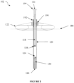
- FIG. 2 illustrates the wave-powered pump of the wave-powered desalinator system in accordance with second aspect of the present disclosure.
- the wave-powered pump 102 is disclosed.
- the wave-powered pump 102 comprises a pump plunger 118, a pump barrel 120, a float 122.
- the wave-powered pump 102 is configured to at least partially float on seawater and pump the seawater from pump inlet 112 to pump outlet 114 using the motion of waves of the seawater.
- the pump plunger 118 is connected to the support structure and comprises a pump outlet 114 provided near an operative top end of the pump plunger 118.
- the support structure is selected from a floating type support structure or a support structure fixed to seabed.
- the floating type support structure is configured to float on the seawater.
- the pump barrel 120 comprises a fluid inlet 126 provided at an operative bottom end of the pump barrel 120.
- An operative top end of the pump barrel 120 is slidably connected to the outer periphery of the pump plunger 118 and is configured to slide along length of the pump plunger 118.
- a sealing member 192 is disposed at the operative top end of the pump plunger 118 and the pump barrel 120.
- the pump barrel 120 comprises an inlet valve 124 located near the fluid inlet 126 submerged in the fluid and the inlet valve 124 is configured to allow entry of the fluid inside pump cavity and prevent discharge of fluid from the fluid inlet 126.
- the pump plunger 118 and the pump barrel 120 are configured to form a pump cavity between the outer periphery of the pump plunger 118 and the inner periphery of the pump barrel 120.
- the pump plunger 118 comprises an outlet valve 128 located near the operative bottom end of the pump plunger 118.
- the outlet valve 128 is configured to allow discharge of pumped water from the pump cavity towards the pump outlet 114.
- the float 122 is connected to the outer periphery of the pump barrel 120 using an elastomeric joint 190.
- the elastomeric joint 190 allows limited rotation so that the float aligns itself to the slope of the incoming wave.
- the float is configured to float on the seawater enabling other components of pump to float on the seawater.
- the float is configured to move vertically along with the pump barrel 120.
- the float 122 is made of water-resistant material.
- the pump barrel 120 comprises a filter screen 130 at the fluid inlet 126.
- the filter screen is configured to prevent the entry of undesired solid objects in the pump barrel, otherwise these solid objects may damage the pump structure. During the operation of the pump, the solid objects may get trapped in the filter screen.
- a self-cleaning mechanism is provided to clean the filter screen 130.
- the pump plunger 118 serves a dual purpose of pressurizing fluid as well as providing flow path towards outlet through its inner hollow structure. This reduces number of parts and complexity of wave powered pump.
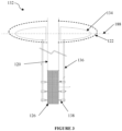
- Figure 3 illustrates the self-cleaning mechanism of the wave-powered desalinator system in accordance with an embodiment of the present disclosure
- the self-cleaning mechanism 132 comprises, a secondary float 134, at least a support member 136, and a plurality of wiping means 138.
- the secondary float 134 is connected to the float 122 using a connecting means.
- the secondary float 134 is configured to move vertically relative to the float 122.
- the secondary float 134 is made of water-resistant material.
- the support member is long structure having one end connected to the secondary float 134. At the other end of the support member 136 a plurality of wiping means 138 are connected. Wiping means are configured to project towards the outer surface of the filter screen 130.
- the support member 136 is selected from a rod or a pipe.
- the wiping means 138 are configured to scrub and clean the filter screen 130 during operative condition of the wave powered pump.
- the wiping means 138 comprises a plurality of rings with outer peripheral edge attached to the support member 136, and inner peripheral edge is configured to scrub the filter screen 130.
- the wiping means 138 comprises plurality of scraper blades with one end of said scraper blade connected to the support member 136 and another end is configured to scrub the filter screen 130.
- the self-cleaning mechanism 132 reduces frequent maintenance and cleaning of filter screen.
- the wave powered pumps is in fluid communication with the pressure intensifier unit 106.
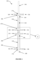
- the pressure intensifier unit 106 according to the third aspect of the present invention, is shown in figure 4 and figure 5 .
- the pressure intensifier unit 106 comprises a first pump cylinder 140 and a second pump cylinder 142 disposed co-axial with the first pump cylinder 140.
- the first pump cylinder 140 and the second pump cylinder 142 are separated by a spacer 186.
- the first pump cylinder 140 is in fluid communication with the second pump cylinder 142.
- the first pump cylinder 140 accommodates a first piston 144 that is configured to slide inside the first pump cylinder 140.
- the second pump cylinder 142 accommodates a second pump piston 146 that is configured to slide inside the second pump cylinder 142.
- a tie rod 164 is provided to connect the first side of the first piston 144 with the first side of the second piston 146.
- Each of the first pump cylinder 140 and the second pump cylinder 142 comprises a seawater inlet port 148,150.
- the low-pressure seawater supplied by the wave powered pump/s 102 enters cylinders 140,142 through seawater inlet port 148,150 respectively.
- Each of the first pump cylinder 140 and the second pump cylinder 142 comprises a seawater outlet port 152,154.
- the high-pressure seawater is discharged out of the cylinders 140,142 through seawater outlet port 152,154.
- each of the first pump cylinder 140 and the second pump cylinder 142 comprises a brine inlet port 156, 158.
- the high-pressure brine discharged by the RO membrane unit is supplied into cylinders 140,142 through a brine inlet port 156, 158.
- pressure intensifier acts as energy recovery device that utilizes energy of high pressure brine for increasing pressure of seawater.
- the low-pressure brine is discharged out of cylinders 140,142 through a brine outlet port 160,162.
- a check valve is disposed at each seawater inlet port 148,150 and each seawater outlet port 152,154.
- a control valve is disposed at each brine inlet port 156, 158 and each brine outlet port 160,162 to control the flow of brine entering and escaping cylinders 140,142.
- the high-pressure brine discharged by the RO membrane unit 108 enters the first pump cylinder 140 through brine inlet port 156, causing movement of the first piston 144 from the second end 182 to a first end 178 and the second piston 146 from the first end 180 to the second end 184.
- the movement of the first piston 144 causes pressurized seawater inside first cylinder pump 140 to be discharged through seawater outlet port 152.
- the brine in second pump cylinder 142 is discharged through brine outlet port 162, while allowing entry of seawater inside second pump cylinder
- the high-pressure brine discharged by the RO membrane unit 108 enters the second pump cylinder 142 through brine inlet port 158, causing movement of the first piston 144 form first end 180 to the second end 182 and the second piston 146 from the second end 184 to the first end 180.
- the movement of the second piston 146 causes pressurized seawater inside second pump cylinder 142 to be discharged through seawater outlet port 154.
- the brine in the first pump cylinder 140 is discharged through brine outlet port 160, while allowing entry of seawater inside the first pump cylinder 140.
- a first displacer rod 166 is provided at the second side of the first piston 144 and a second displacer rod 168 is provided at the second side of the second piston 146 and the diameter of the first displacer rod 166 and the second displacer rod 168 is greater than the diameter of the tie rod 164.
- first displacer rod 166 and the second displacer rod 168 are removably installed in the first pump cylinder 140 and the second pump cylinder 142 respectively.
- each displacer rod 166, 168 affects the effective area of the piston 144,146 on which brine exerts pressure.
- the effective area of the piston 144,146 governs the fresh water recovery rate.
- cylinders 140, 142 may have a stroke length of 3 meters.
- a first bearing seal assembly 170 and a second a bearing seal assembly 172 is disposed at the first end 178,180 of the first pump cylinder 140 and the second pump cylinder 142 respectively.
- the first bearing seal assembly 170 is configured to seal the first end 178 of the first pump cylinder 140 and the tie rod 164.
- the second bearing seal assembly 172 is configured to seal the first end 180 of the second pump cylinder 142 and the tie rod 164.
- a third bearing seal assembly 174 and a fourth bearing seal assembly 176 is disposed at the second end 182,184 of the first pump cylinder 140 and the second pump cylinder 142 respectively.
- the third bearing seal assembly 174 is configured to seal the second end 182 of the first pump cylinder 140 and the first displacer rod 166.
- the second bearing seal assembly 172 is configured to seal the second end 184 of the second pump cylinder 142 and the second displacer rod 168.
- the first bearing seal assembly 170, the second bearing seal assembly 172, the third bearing seal assembly 174 and the fourth bearing seal assembly 176 are packing gland type seals.
- the packing gland type seals allow replacement of split ring seals for maintenance without disassembly, which makes the bearing assembly 170,172,174 and 176 externally accessible.
- the externally accessible arrangement of the bearing seal assemblies 170, 172,174,176 reduces the steps required in maintenance process, hence reducing maintenance time.
- the length of the pressure intensifier unit 106 may be 12 meters.
- the desalinator system uses cylindrical barrels in wave-powered pump 102, pressure vessels of RO membrane unit 108 and cylinders 140,142 of pressure intensifier unit 106. To reduce complexity of design, these cylindrical barrels are designed to have same diameter but different length as per the requirement.
- cylindrical barrel is filament wound composite barrel.
- the cylindrical barrel may be made of corrosion resistant material such as stainless steel, copper etc.
- cylindrical barrel is designed to have inner diameter of 16 inch and pressure rating of 60 Bar.
- in an operative configuration of the wave-powered desalinator system 100 includes array of twenty pumps.
- the feed water flow from pumps 102 is nominally 830 cubic meter per hour, (400 m 3 /h min.- 1600 m 3 /h max.).
- the permeate (fresh water) recovery rate is 10%.
- the single membrane recovery rate is 5%.
- Fresh water recovery rate is controlled by changing the pressure intensifier design. Feed pressure varies according to the feed flow between 30 and 60 Bar. Fouling resistant type SWRO membranes are selected and thicker feed spacer is used.
Landscapes
- Engineering & Computer Science (AREA)
- Chemical & Material Sciences (AREA)
- Water Supply & Treatment (AREA)
- Organic Chemistry (AREA)
- Environmental & Geological Engineering (AREA)
- Hydrology & Water Resources (AREA)
- Life Sciences & Earth Sciences (AREA)
- Combustion & Propulsion (AREA)
- Mechanical Engineering (AREA)
- General Engineering & Computer Science (AREA)
- Nanotechnology (AREA)
- Chemical Kinetics & Catalysis (AREA)
- Separation Using Semi-Permeable Membranes (AREA)
Priority Applications (2)
| Application Number | Priority Date | Filing Date | Title |
|---|---|---|---|
| EP23207463.3A EP4549406A1 (fr) | 2023-11-02 | 2023-11-02 | Un système de dessalement alimenté par les vagues |
| PCT/EP2024/080569 WO2025093542A1 (fr) | 2023-11-02 | 2024-10-29 | Système de dessalement à houle |
Applications Claiming Priority (1)
| Application Number | Priority Date | Filing Date | Title |
|---|---|---|---|
| EP23207463.3A EP4549406A1 (fr) | 2023-11-02 | 2023-11-02 | Un système de dessalement alimenté par les vagues |
Publications (1)
| Publication Number | Publication Date |
|---|---|
| EP4549406A1 true EP4549406A1 (fr) | 2025-05-07 |
Family
ID=88689486
Family Applications (1)
| Application Number | Title | Priority Date | Filing Date |
|---|---|---|---|
| EP23207463.3A Pending EP4549406A1 (fr) | 2023-11-02 | 2023-11-02 | Un système de dessalement alimenté par les vagues |
Country Status (2)
| Country | Link |
|---|---|
| EP (1) | EP4549406A1 (fr) |
| WO (1) | WO2025093542A1 (fr) |
Citations (9)
| Publication number | Priority date | Publication date | Assignee | Title |
|---|---|---|---|---|
| US5499889A (en) * | 1992-05-22 | 1996-03-19 | Yim; Myung-Shik | Wave power generator |
| US6017200A (en) * | 1997-08-12 | 2000-01-25 | Science Applications International Corporation | Integrated pumping and/or energy recovery system |
| ITPN20080084A1 (it) * | 2008-11-11 | 2010-05-11 | Antonio Lus | "impianto a moto ondoso utilizzante mezzi galleggianti per produrre energia" |
| US20130052042A1 (en) * | 2009-09-09 | 2013-02-28 | Dartmouth Wave Energy Limited | Pumping device |
| WO2014100674A1 (fr) * | 2012-12-21 | 2014-06-26 | Resolute Marine Energy, Inc. | Système de dessalement à houle intégré |
| CN104061205A (zh) * | 2014-05-30 | 2014-09-24 | 广西大学 | 一种压力交换能量回收缸 |
| US20190151798A1 (en) * | 2016-06-10 | 2019-05-23 | Oneka Technologies | System and method for desalination of water by reverse osmosis |
| WO2022113024A1 (fr) * | 2020-11-26 | 2022-06-02 | Oneka Technologies | Système actionné par les vagues, sous-système de convertisseur d'énergie houlomotrice et procédé de fonctionnement d'un sous-système de dessalement par osmose inverse |
| NO20210590A1 (no) * | 2021-05-12 | 2022-11-14 | Ocean Oasis As | Anordning for fluidbehandling |
-
2023
- 2023-11-02 EP EP23207463.3A patent/EP4549406A1/fr active Pending
-
2024
- 2024-10-29 WO PCT/EP2024/080569 patent/WO2025093542A1/fr active Pending
Patent Citations (9)
| Publication number | Priority date | Publication date | Assignee | Title |
|---|---|---|---|---|
| US5499889A (en) * | 1992-05-22 | 1996-03-19 | Yim; Myung-Shik | Wave power generator |
| US6017200A (en) * | 1997-08-12 | 2000-01-25 | Science Applications International Corporation | Integrated pumping and/or energy recovery system |
| ITPN20080084A1 (it) * | 2008-11-11 | 2010-05-11 | Antonio Lus | "impianto a moto ondoso utilizzante mezzi galleggianti per produrre energia" |
| US20130052042A1 (en) * | 2009-09-09 | 2013-02-28 | Dartmouth Wave Energy Limited | Pumping device |
| WO2014100674A1 (fr) * | 2012-12-21 | 2014-06-26 | Resolute Marine Energy, Inc. | Système de dessalement à houle intégré |
| CN104061205A (zh) * | 2014-05-30 | 2014-09-24 | 广西大学 | 一种压力交换能量回收缸 |
| US20190151798A1 (en) * | 2016-06-10 | 2019-05-23 | Oneka Technologies | System and method for desalination of water by reverse osmosis |
| WO2022113024A1 (fr) * | 2020-11-26 | 2022-06-02 | Oneka Technologies | Système actionné par les vagues, sous-système de convertisseur d'énergie houlomotrice et procédé de fonctionnement d'un sous-système de dessalement par osmose inverse |
| NO20210590A1 (no) * | 2021-05-12 | 2022-11-14 | Ocean Oasis As | Anordning for fluidbehandling |
Also Published As
| Publication number | Publication date |
|---|---|
| WO2025093542A1 (fr) | 2025-05-08 |
Similar Documents
| Publication | Publication Date | Title |
|---|---|---|
| US7563375B2 (en) | Direct osmosis cleaning | |
| KR102266110B1 (ko) | 감압 염수 처리 시스템 | |
| JP6762258B2 (ja) | 逆浸透処理システム及び逆浸透処理方法 | |
| US4243523A (en) | Water purification process and system | |
| JP5880432B2 (ja) | 塩水淡水化装置 | |
| EA012219B1 (ru) | Устройство без ёмкостей и с замкнутым циклом для непрерывного опреснения | |
| WO2021087472A1 (fr) | Système de dessalement d'eau immergée à pompe à distance | |
| CN110713279B (zh) | 海水淡化水处理装置 | |
| US20110290728A1 (en) | SWRO Pressure Vessel and Process That Increases Production and Product Quality and Avoids Scaling Problems | |
| WO2025093542A1 (fr) | Système de dessalement à houle | |
| KR20110138351A (ko) | 농축물이 순환하고 탱크 내 막을 갖춘 연속처리 회분식 역삼투압 시스템 | |
| US20240059586A1 (en) | Seawater RO desalination by pneumatic power tapped from offshore ocean wave energy | |
| CN1429648A (zh) | 微滤机 | |
| JP2011115704A (ja) | 塩水淡水化装置 | |
| RU22434U1 (ru) | Установка для разделения растворов | |
| CN205773684U (zh) | 一种船舰用海水淡化装置 | |
| Peters | Desalination of seawater and brackish water with reverse osmosis and the disc tube module DT | |
| KR20120133313A (ko) | 조수시스템 및 조수방법 | |
| CN210237267U (zh) | 船用海水淡化处理装置 | |
| CN211141709U (zh) | 一种净化水用水处理系统 | |
| CN106554098B (zh) | 便携式海水淡化器 | |
| KR102328973B1 (ko) | 분리막 역세척이 가능한 수처리 시스템 | |
| RU2837054C1 (ru) | Система фильтрации жидкости через полупроницаемые мембраны с использованием гидростатического давления | |
| US11261102B2 (en) | Reverse osmosis prefilter system | |
| CN209923056U (zh) | 一种码头船舶油污水接收处理装置 |
Legal Events
| Date | Code | Title | Description |
|---|---|---|---|
| PUAI | Public reference made under article 153(3) epc to a published international application that has entered the european phase |
Free format text: ORIGINAL CODE: 0009012 |
|
| STAA | Information on the status of an ep patent application or granted ep patent |
Free format text: STATUS: THE APPLICATION HAS BEEN PUBLISHED |
|
| AK | Designated contracting states |
Kind code of ref document: A1 Designated state(s): AL AT BE BG CH CY CZ DE DK EE ES FI FR GB GR HR HU IE IS IT LI LT LU LV MC ME MK MT NL NO PL PT RO RS SE SI SK SM TR |
|
| STAA | Information on the status of an ep patent application or granted ep patent |
Free format text: STATUS: REQUEST FOR EXAMINATION WAS MADE |
|
| 17P | Request for examination filed |
Effective date: 20251027 |