EP4549691A2 - Tür- und fensterrahmen sowie zugehörige verfahren - Google Patents
Tür- und fensterrahmen sowie zugehörige verfahren Download PDFInfo
- Publication number
- EP4549691A2 EP4549691A2 EP25164567.7A EP25164567A EP4549691A2 EP 4549691 A2 EP4549691 A2 EP 4549691A2 EP 25164567 A EP25164567 A EP 25164567A EP 4549691 A2 EP4549691 A2 EP 4549691A2
- Authority
- EP
- European Patent Office
- Prior art keywords
- frame assembly
- door frame
- window
- wall
- door
- Prior art date
- Legal status (The legal status is an assumption and is not a legal conclusion. Google has not performed a legal analysis and makes no representation as to the accuracy of the status listed.)
- Pending
Links
Images


Classifications
-
- E—FIXED CONSTRUCTIONS
- E06—DOORS, WINDOWS, SHUTTERS, OR ROLLER BLINDS IN GENERAL; LADDERS
- E06B—FIXED OR MOVABLE CLOSURES FOR OPENINGS IN BUILDINGS, VEHICLES, FENCES OR LIKE ENCLOSURES IN GENERAL, e.g. DOORS, WINDOWS, BLINDS, GATES
- E06B1/00—Border constructions of openings in walls, floors, or ceilings; Frames to be rigidly mounted in such openings
- E06B1/04—Frames for doors, windows, or the like to be fixed in openings
- E06B1/12—Metal frames
- E06B1/18—Metal frames composed of several parts with respect to the cross-section of the frame itself
- E06B1/20—Metal frames composed of several parts with respect to the cross-section of the frame itself adjustable with respect to the thickness of walls
-
- E—FIXED CONSTRUCTIONS
- E06—DOORS, WINDOWS, SHUTTERS, OR ROLLER BLINDS IN GENERAL; LADDERS
- E06B—FIXED OR MOVABLE CLOSURES FOR OPENINGS IN BUILDINGS, VEHICLES, FENCES OR LIKE ENCLOSURES IN GENERAL, e.g. DOORS, WINDOWS, BLINDS, GATES
- E06B1/00—Border constructions of openings in walls, floors, or ceilings; Frames to be rigidly mounted in such openings
- E06B1/04—Frames for doors, windows, or the like to be fixed in openings
- E06B1/12—Metal frames
- E06B1/18—Metal frames composed of several parts with respect to the cross-section of the frame itself
-
- E—FIXED CONSTRUCTIONS
- E06—DOORS, WINDOWS, SHUTTERS, OR ROLLER BLINDS IN GENERAL; LADDERS
- E06B—FIXED OR MOVABLE CLOSURES FOR OPENINGS IN BUILDINGS, VEHICLES, FENCES OR LIKE ENCLOSURES IN GENERAL, e.g. DOORS, WINDOWS, BLINDS, GATES
- E06B1/00—Border constructions of openings in walls, floors, or ceilings; Frames to be rigidly mounted in such openings
- E06B1/04—Frames for doors, windows, or the like to be fixed in openings
- E06B1/26—Frames of plastics
- E06B1/30—Frames of plastics composed of several parts with respect to the cross-section of the frame itself
-
- E—FIXED CONSTRUCTIONS
- E06—DOORS, WINDOWS, SHUTTERS, OR ROLLER BLINDS IN GENERAL; LADDERS
- E06B—FIXED OR MOVABLE CLOSURES FOR OPENINGS IN BUILDINGS, VEHICLES, FENCES OR LIKE ENCLOSURES IN GENERAL, e.g. DOORS, WINDOWS, BLINDS, GATES
- E06B1/00—Border constructions of openings in walls, floors, or ceilings; Frames to be rigidly mounted in such openings
- E06B1/04—Frames for doors, windows, or the like to be fixed in openings
- E06B1/52—Frames specially adapted for doors
-
- E—FIXED CONSTRUCTIONS
- E06—DOORS, WINDOWS, SHUTTERS, OR ROLLER BLINDS IN GENERAL; LADDERS
- E06B—FIXED OR MOVABLE CLOSURES FOR OPENINGS IN BUILDINGS, VEHICLES, FENCES OR LIKE ENCLOSURES IN GENERAL, e.g. DOORS, WINDOWS, BLINDS, GATES
- E06B3/00—Window sashes, door leaves, or like elements for closing wall or like openings; Layout of fixed or moving closures, e.g. windows in wall or like openings; Features of rigidly-mounted outer frames relating to the mounting of wing frames
- E06B3/04—Wing frames not characterised by the manner of movement
- E06B3/06—Single frames
- E06B3/24—Single frames specially adapted for double glazing
Definitions
- This disclosure relates generally to construction elements, and relates more particularly to door frames and window frames, and related methods.
- an underlying bare surface such as, for example, a wall or floor
- dust, dirt, grime, grease, bacteria, insects, animals, and any other deleterious elements For example, in a commercial environment (such as, for example, a restaurant, cafeteria, food stand, or cleanroom) surface finishing items are generally installed over a bare surface to create a finished or working surface.
- surface finishing items cover and treat bare surfaces using one or more of wall board, sheet rock, plaster, backsplashes, tile, wallpaper, carpeting, wood, paneling, vinyl, and other similar materials.
- Couple should be broadly understood and refer to connecting two or more elements mechanically and/or otherwise. Two or more mechanical elements may be mechanically coupled together, but not be electrically or otherwise coupled together. Coupling may be for any length of time, e.g., permanent or semi-permanent or only for an instant. "Mechanical coupling” and the like should be broadly understood and include mechanical coupling of all types.
- two or more elements are “integral” if they are comprised of the same piece of material. As defined herein, two or more elements are “non-integral” if each is comprised of a different piece of material.
- “approximately” can, in some embodiments, mean within plus or minus ten percent of the stated value. In the same or different embodiments, “approximately” can mean within plus or minus five percent of the stated value. In further embodiments, “approximately” can mean within plus or minus three percent of the stated value. In yet other embodiments, “approximately” can mean within plus or minus one percent of the stated value. In some embodiments, “approximately” can mean within plus or minus ten degrees of the stated value. In the same or different embodiments, “approximately” can mean within plus or minus five degrees of the stated value. In yet other embodiments, “approximately” can mean within plus or minus one degree of the stated value.
- the terms “comprise”, “comprises”, “comprising”, “having”, “including”, “includes”, “is” or any variation thereof, are intended to reference a non-exclusive inclusion, such that a process, method, article, composition, system, device, or apparatus that comprises a list of elements does not include only those elements recited, but may also include other elements not expressly listed or inherent to such process, method, article, composition, system, device, or apparatus.
- a construction element may be described herein by terms of various functional elements and various method steps. Such functional elements may be realized by any number of hardware components adapted to perform generalized or specific functions to achieve various results.
- the construction element may employ various construction element components, e.g., various materials, such as stainless steel, standard steel grades, aluminum, copper, various alloy combinations, vinyl, and any other natural and/or synthetic materials whether now known or developed in the future.
- the construction element may comprise various structural configurations, for example, tongue and grooves, slots, laps, welds, snaps, latches, wells, and the like, which may carry out a variety of functions.
- each structural configuration may comprise any number or permutations of configurations; for example, various scale, gauge, finish, size, geometry, surface texture, and the like may be employed.
- construction element may be practiced as part of any variety of construction elements and/or finishing applications, whether for commercial, industrial, and/or residential purpose; and any particular system, method, and/or purpose described herein is merely exemplary for the construction element.
- construction element may be practiced by any number of other applications and environments, whether now known or developed in the future.
- construction element may employ any number of conventional techniques for manufacturing, installing, packaging, marketing, distributing, and/or selling the construction element.
- a construction element (such as, for example, baseboards, crown molding, wainscoting, door frames, and window frames) can (1) operate to seal and/or operate as a transition from one surface finishing item to another (such as, for example, wall board, sheet rock, plaster, backsplashes, tile, wallpaper, carpeting, wood, paneling, or vinyl), (2) prevent deleterious materials (such as, for example, dirt, grime, grease, bacteria, insects, or animals) from accumulating or growing at the location of the construction element, and (3) prevent the deleterious materials from contacting the base surfaces underlying the surface finishing items.
- the construction element can be referred to as a construction trim element.
- a door frame assembly or window frame assembly can be applied to any construction system.
- FIG. 1 illustrates an exemplary embodiment of a door frame assembly 100.
- the door frame assembly is shown in a top-down view.
- the door frame assembly can be bent into shape from a single, integrated piece of material.
- the door frame assembly can be made of metal, such as 20 gauge 304 stainless steel.
- the door frame assembly can be made of a different type or metal or a different type of material that is malleable or pliable.
- the dimensions shown in FIG. 1 are exemplary, are shown in inches (and can be converted to centimeters by multiplying the numerical values in FIG. 1 by 2.54), and can vary depending on the requirements for the door frame assembly.
- the door frame assembly can replace the typical door trim that is often used around a door.
- the door frame assembly can be inserted over an end of a wall (e.g., a doorjamb) and can be attached to the wall with mechanical fasteners such as nails, rivets, and/or screws.
- the door frame assembly can have holes to receive the mechanical fasteners. All or a portion of the door frame assembly can be flush with the end of the wall.
- Portion 101 of door frame assembly 100 that is shown as 1.65 inches wide can serve as a typical door stop for a closed door. Ends of wall coverings that cover the wall can be inserted into the upside-down U-shaped portions on the right and left sides of the door frame assembly, as shown in FIG. 1 .
- the wall coverings (not shown in FIG. 1 ) can be made of composite materials such as fiber-reinforced plastic or fiber-reinforced polymer (FRP). In other embodiments, the wall coverings can be made of other materials.
- FIG. 2 illustrates an exploded view of an exemplary embodiment of a door frame assembly 200 at an end of wall 209.
- the door frame assembly is shown in a top-down view.
- the door frame assembly shown in FIG. 2 is too large for the wall shown in FIG. 2 , and is drawn larger than desired in FIG. 2 to more easily explain the concepts presented herein.
- Door frame assembly 200 has portions 201, portions 203, portions 204, raised portion 206, edge 207, and portion 208.
- the door frame assembly can be bent into shape from a single, integrated piece of material.
- the door frame assembly can be made of a metal, such as 20 gauge 304 stainless steel.
- the door frame assembly can be made of a different type of metal or other material that is malleable or pliable.
- the door frame assembly can replace the typical door trim that is often used around a door.
- the door frame assembly can be inserted over an end of wall 209 and serve as a doorjamb.
- Portions 204 of door frame assembly 200 can be attached to the wall with mechanical fasteners such as nails, rivets, and/or screws.
- the door frame assembly can have holes at portions 204 to receive the mechanical fasteners.
- All or a portion of the door frame assembly can be flush with the end of the wall.
- portions 204 can be flush with the end of wall 209, while raised portion 206 would not be flush with the end of the wall, as illustrated in FIG. 2 .
- raised portion 206 can provide a spring-like effect on door 202 if door 202 contacts edge 207 of raised portion 206 when door 202 is closing.
- portion 208 of door frame assembly 200 is flush with the end of wall 209, and in another embodiment, portion 208 is not flush with the end of wall 209, similar to raised portion 206, except that a distance separating portion 208 from the end of wall 209 would be smaller than a distance separating raised portion 206 from the end of wall 209.
- portions 201 of door frame assembly 200 can be separated from and not flush with the end of wall 209, while portions 204 can be flush with the end of wall 209.
- the wall coverings can be made of composite materials such as fiber-reinforced plastic or fiber-reinforced polymer (FRP). In other embodiments, the wall coverings can be made of other materials.
- a spring inside element 205 can be attached to the door frame assembly (and possibly the wall) using one or more mechanical fasteners such as one or more nails, rivets, and/or screws.
- the trim assemblies can cover portions of door frame assembly 200 and also can cover or not cover portions of the wall coverings.
- the springs can be attached to the outer portion of portions 201 and/or 203 at only or both sides of door frame assembly 200.
- Each spring can be approximately 1/4 inch to 1 inch wide (or 3/8 inch to 1/2 inch wide) and can have one or more holes to receive the one or more mechanical fasteners to attach the spring to door frame assembly 200.
- the one or more mechanical fasteners used to attach the spring to the door frame assembly can be the same or different as the mechanical fasteners previously described to attach the door frame assembly to the wall.
- the door frame assembly of FIG. 1 also can have this embodiment and its variations.
- the spring covers are attached to the door frame assembly, and the springs are attached to the trim assembly.
- the springs can be attached to the door frame assembly by securing the mechanical fasteners through the door frame assembly and the wall coverings.
- FIGs. 3A, 3B, and 3C illustrate additional details of the door frame assembly of FIG. 2 .
- a single, flat piece of material can be cut to an appropriate shape and folded or bent in a particular manner to create the door frame assembly in this embodiment.
- the dimensions shown in FIGs. 3A and 3C are exemplary, are shown in inches (and can be converted to centimeters by multiplying the numerical values in FIG. 3 by 2.54), and can vary depending on the requirements for the door frame assembly.
- the first or top horizontal line across the width of door frame assembly 200 is located at the 2.01 inch mark on left side of door frame assembly 200.
- This first horizontal line represents the location of a first bend in door frame assembly 200.
- This first bend can be a 180 degree "up" bend having a 0.05 inch radius.
- the second-from-the-top horizontal line across the width of door frame assembly 200 is located at the 2.60 inch mark on the left side of door frame assembly 200.
- This second horizontal line represents the location of a second bend in door frame assembly 200.
- This second bend can be a 180 degree "down" bend having a 0 inch radius.
- the third horizontal line across the width of door frame assembly 200 is located at the 4.57 inch mark on the left side of door frame assembly 200.
- This third horizontal line represents the location of a third bend in door frame assembly 200.
- This third bend can be a 90 degree "down" bend having a 0.04 inch radius.
- the fourth horizontal line across the width of door frame assembly 200 is located at the 6.48 inch mark on the left side of door frame assembly 200.
- This fourth horizontal line represents the location of a fourth bend in door frame assembly 200.
- This fourth bend can be a 90 degree "up" bend having a 0.04 inch radius.
- the fifth horizontal line across the width of door frame assembly 200 is located at the 7.08 inch mark on the left side of door frame assembly 200.
- This fifth horizontal line represents the location of a fifth bend in door frame assembly 200.
- This fifth bend can be a 90 degree "down" bend having a 0.04 inch radius.
- the sixth horizontal line across the width of door frame assembly 200 is located at the 10.61 inch mark on the left side of door frame assembly 200.
- This sixth horizontal line represents the location of a sixth bend in door frame assembly 200.
- This sixth bend can be a 90 degree "down" bend having a 0.04 inch radius.
- the seventh horizontal line across the width of door frame assembly 200 is located at the 12.58 inch mark on the left side of door frame assembly 200.
- This seventh horizontal line represents the location of a seventh bend in door frame assembly 200.
- This seventh bend can be a 180 degree "down" bend having a 0 inch radius.
- the eighth or bottom-most horizontal line across the width of door frame assembly 200 is located at the 13.16 inch mark on the left side of door frame assembly 200.
- This eighth horizontal line represents the location of an eighth bend in door frame assembly 200.
- This eighth bend can be a 180 degree "up" bend having a 0.05 inch radius.
- three door frame assemblies can be used for a single door -- a first door frame assembly on the left side of the door, a second door frame assembly on the right side of the door, and a third door frame assembly at the top of the door.
- the door frame assembly illustrated in FIGs. 2 and 3A-3C can be the first door frame assembly on the left side of the door.
- the first and second door frame assemblies can be mirror images of each other, and the third door frame assembly can be similar to the first and second door frame assemblies.
- the first, second, and third door frame assemblies can have edges that are complementary to each other to allow the first and third door frame assemblies to interlock or otherwise fit together and to allow the second and third door frame assemblies to similarly interlock or otherwise fit together.
- the joints between the first, second, and third door frame assemblies can be optionally sealed by a sealant such as caulk or silicone.
- this three-piece configuration can be manufactured using a casting, welding, hydro-forming, pressing, or injecting process to create a one-piece assembly.
- this three-piece configuration and the one-piece assembly also apply to the embodiment of the door frame assembly of FIG. 1 , and the three-piece configuration and one-piece assembly also can be used in a double door embodiment.
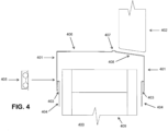
- FIG. 4 illustrates an exploded view of an exemplary embodiment of a door frame assembly 400 at an end of wall 409.
- the door frame assembly is shown in a top-down view.
- the door frame assembly shown in FIG. 4 is too large for the wall shown in FIG. 4 , and is drawn larger than desired in FIG. 4 to more easily explain the concepts presented herein.
- Door frame assembly 400 has portions 401, portions 403, portions 404, raised portion 406, bump 407, and portion 408.
- the door frame assembly can be bent into shape from a single, integrated piece of material.
- the door frame assembly can be made of metal, such as 20 gauge 304 stainless steel.
- the door frame assembly can be made of a different type of metal or other material that is malleable or pliable.
- the door frame assembly of FIG. 4 can be similar to the door frame assemblies of FIGs. 1-3 , such that the elements of FIG. 4 having reference numbers with the same last two digits as reference numbers in FIGs. 1-3 can represent similar elements in FIG. 1-3 .
- door frame assembly 400 of FIG. 4 has a bevel profile where door 402 closes against portion 408 of door frame assembly 400 while the door frame assemblies of FIGs. 1-3 have a more traditional door stop profile.
- the bevel profile of door frame assembly 400 of FIG. 4 includes bump 407 and raised portion 406, as well as portion 408, that can assist in stopping or at least slowing down a closing door.
- the bevel profile, including bump 407 and portion 408 which are not flush will wall 409, can have a spring-like effect on the door if the door contacts the bevel profile when the door is closing.
- the door frame assembly can replace the typical door trim that is often used around a door.
- the door frame assembly of FIG. 4 can be inserted over an end of wall 409 and serve as a doorjamb.
- Portion 404 of door frame assembly 400 and can be attached to the wall with mechanical fasteners such as nails, rivets, and/or screws.
- the door frame assembly can have holes at portions 404 to receive the mechanical fasteners.
- All or a portion of the door frame assembly can be flush with the end of the wall.
- portions 404 can be flush with the end of wall 409, while raised portion 406 and the beveled portion (including portions 407-408) would not be flush with the end of the wall, as illustrated in FIG. 4 .
- all or some of the beveled portion is flush with the end of the wall.
- portions 401 of door frame assembly 400 can be separated from and not flush with the end of wall 409.
- the wall coverings can be made of composite materials such as fiber-reinforced plastic or fiber-reinforced polymer (FRP). In other embodiments, the wall coverings can be made of other materials.
- springs and/or spring covers inside element 405 can be attached to door frame assembly 400 (and possibly the end of wall 409), similar to how springs and spring covers inside element 205 ( FIG. 2 ) were described above to be attached to door frame assembly 200 ( FIG. 2 ).
- the embodiment of the door frame assembly in FIG. 4 can use three door frame assemblies for a single door -- a first door frame assembly on the left side of the door, a second door frame assembly on the right side of the door, and a third door frame assembly at the top of the door.
- the door frame assembly illustrated in FIG. 4 can be the first door frame assembly on the left side of the door.
- the second and third door frame assemblies can be similar to the first door frame assembly, and can be more similar to each other in shape than to the first door frame assembly.
- the first, second, and third door frame assemblies can have edges that are complementary to each other to allow the first and third door frame assemblies to interlock or otherwise fit together and to allow the second and third door frame assemblies to similarly interlock or otherwise fit together.
- the joints between the first, second, and third door frame assemblies can be optionally sealed by a sealant such as caulk or silicone.
- this three-piece configuration can be manufactured using a casting, welding, hydro-forming, pressing, or injecting process to create a one-piece assembly.
- the three door frame assemblies and one-piece assemblies can be used in a double door configuration.
- FIG. 5 illustrates an exploded view of an exemplary embodiment of a door frame assembly 500 that is adjustable at an end of wall 509 and that has a bevel profile.
- the door frame assembly is shown in a top-down view.
- the door frame assembly can be a multi-piece assembly, where each piece is bent into its respective shape. More specifically, door frame assembly 500 can be a two-piece assembly with portions 510 and 511. Portion 510 can be the fixed side and the strike side where door 502 strikes door frame assembly 500 when closing, and portion 511 can be the adjustable side. Each of portions 510 and 511 have portions 501, 503, and 504. Portion 510 also has raised portion 506, bump 507, and portion 508, as well as groove 512. Portion 511 has portion 513 for insertion into groove 512.
- each of portions 510 and 511 can be bent into shape from a single, integrated piece of material.
- each of portions 510 and 511 can be made of metal, such as 20 gauge 304 stainless steel.
- each of portions 510 and 511 can be made of a different type of metal or other material that is malleable or pliable.
- the door frame assembly of FIG. 5 can be similar to the door frame assemblies of FIGs. 1-4 , such that the elements of FIG. 5 having reference numbers with the same last two digits as reference numbers in FIGs. 1-4 can represent similar elements in FIGs. 1- 4 .
- Both door frame assemblies in FIGs. 4 and 5 have a bevel profile where the door closes against a portion (portion 508 in FIG. 5 ) of the door frame assembly, and also have a bump (bump 507 in FIG. 5 ) and raised portion (portion 506 in FIG. 5 ) next to the bevel profile that can assist in stopping or at least slowing down the door (door 502 in FIG. 5 ) that is closing.
- a bump 507 in FIG. 5 bump 507 in FIG. 5
- portion 506 in FIG. 5 next to the bevel profile that can assist in stopping or at least slowing down the door (door 502 in FIG. 5 ) that is closing.
- the bevel profile including bump 507 and portion 508 which are not flush will wall 509, can have a spring-like effect on door 502 and/or gasket 514 of door 502 if door 502 and/or gasket 514 contacts the bevel profile when door 502 is closing.
- FIG. 6 illustrates an assembled view of door frame 500 around the end of wall 509, but the door, which has a width of approximately 1.75 inches in this embodiment, in FIG. 6 does not have a door seal or gasket, unlike door 502 in FIG. 5 .
- FIG. 6 shows portions 504 of portions 510 and 511 of the door frame assembly flush with the end of the wall, and also shows part of portion 511 that forms groove 512 being flush with the end of the wall.
- FIG. 6 shows portions 501 of portions 510 and 511 not being flush with the end of the wall.
- FIG. 6 also shows portion 513 inserted into groove 512.
- the wall coverings can be made of composite materials such as fiber-reinforced plastic or fiber-reinforced polymer (FRP). In other embodiments, the wall coverings can be made of other materials.
- springs and/or spring covers inside element 505 can be attached to door frame assembly 500 (and possibly the end of wall 509), similar to how springs and spring covers inside element 205 ( FIG. 2 ) were described above to be attached to door frame assembly 200 ( FIG. 2 ).
- FIG. 5 shows the door frame assembly as having gasket 515 that can be used at a joint between portions 510 and 511 of door frame assembly 500.
- gasket 515 can be made of neoprene.
- gasket 515 can be made of a different material that is elastic and/or can be compressed.
- the joint between portions 510 and 511 of the door frame assembly can be sealed with a material such as caulk or silicone.
- the embodiment of the door frame assembly in FIGs. 5-6 can use three door frame assemblies for a single door -- a first door frame assembly on the left side of the door, a second door frame assembly on the right side of the door, and a third door frame assembly at the top of the door.
- the door frame assembly illustrated in FIGs. 5-6 can be the first door frame assembly on the left side of the door.
- the second and third door frame assemblies can be similar to the first door frame assembly, and can be more similar to each other in shape than to the first door frame assembly.
- the first, second, and third door frame assemblies can have edges that are complementary to each other to allow the first and third door frame assemblies to interlock or otherwise fit together and to allow the second and third door frame assemblies to similarly interlock or otherwise fit together.
- this three-piece configuration can be manufactured using a casting, welding, hydro-forming, pressing, or injecting process to create a one-piece assembly.
- the three door frame assemblies and one-piece assemblies can be used in a double door configuration.
- portion 510 of the door frame assembly can be first attached to the wall, along with the corresponding pieces of the two or three other door frame assemblies on the same side of door 502 ( FIG. 5 ). (Two corresponding pieces can be used when the door frame assembly is not installed on the floor or on the threshold of the door, and three corresponding pieces can be used when the door frame assembly is installed on the floor.) Next, portion 511 of the door frame assembly can be attached to the wall on the other side of door 502 ( FIG. 5 ), along with the corresponding pieces of the two or three other door frame assemblies on the other side of door 502 ( FIG. 5 ).
- an optional sealant can be applied to the joints between portions 510 and 511 and the other paired portions of the two or three other door frame assemblies around door 502 ( FIG. 5 ).
- optional springs or spring covers can be attached to portions 510 and/or 511 and the other paired portions of the two or three other door frame assemblies, and optionally the wall, as well, and then optional trim assemblies can be attached to the optional springs or spring covers.
- FIG. 7 illustrates an exploded view of an exemplary embodiment of a door frame assembly 700 that is adjustable at an end of wall 709.
- the door frame assembly is shown in a top-down view.
- the door frame assembly can be a multi-piece assembly, where each piece is bent into its respective shape. More specifically, door frame assembly 700 can be a two-piece assembly with portions 710 and 711. Portion 710 can be the fixed side and the strike side where door 702 strikes door frame assembly 700 when closing, and portion 711 can be the adjustable side. Each of portions 710 and 711 have portions 701, 703, and 704. Portion 710 also has bump 707 and portion 708, as well as groove 712. Portion 711 has portion 713 for insertion into groove 712.
- each of portions 710 and 711 can be bent into shape from a single, integrated piece of material.
- each of portions 710 and 711 can be made of metal, such as 20 gauge 304 stainless steel.
- portions 710 and 711 can be made of a different type of metal or other material that is malleable or pliable.
- the door frame assembly of FIG. 7 can be similar to the door frame assemblies of FIGs. 1-6 , such that the elements of FIG. 7 having reference numbers with the same last two digits as reference numbers in FIGs. 1-6 can represent similar elements in FIGs. 1-6 .
- Both door frame assemblies in FIGs. 5-6 and in FIG. 7 are adjustable to fit different sized walls or doorjambs with different widths.
- the door frame assembly can replace the typical door trim that is often used around a door.
- the door frame assembly of FIG. 7 can be inserted over an end of wall 709 as a doorjamb.
- Portions 704 of door frame assembly 700 can be attached to the wall with mechanical fasteners such as nails, rivets, and/or screws.
- the door frame assembly can have holes at portions 704 to receive the mechanical fasteners.
- portions 704 of portions 710 and 711 can be flush with the end of wall 709, and a part of portion 711 that forms groove 712 also can be flush with the end of wall 709.
- portions 701 are not flush with the end of wall 709. Bump 707 is not flush with the end of wall 709 so that bump 707 can have a spring-like effect on door 702 if door 702 contacts bump 707 when door 702 is closing.
- the wall coverings can be made of composite materials such as fiber-reinforced plastic or fiber-reinforced polymer (FRP). In other embodiments, the wall coverings can be made of other materials.
- springs and/or spring covers inside element 705 can be attached to door frame assembly 700 (and possibly the end of wall 709), similar to how springs and spring covers inside element 205 ( FIG. 2 ) were described above to be attached to door frame assembly 200 ( FIG. 2 ).
- FIG. 7 shows the door frame assembly as having a gasket 715 that can be used at a joint between portions 710 and 711 of door frame assembly 700.
- gasket 715 can be made of neoprene.
- gasket 715 can be made of a different material that is elastic and/or can be compressed.
- the joint between portions 710 and 711 of the door frame assembly can be sealed with a material such as caulk or silicone.
- the embodiment of the door frame assembly in FIG. 7 can use three door frame assemblies for a single door -- a first door frame assembly on the left side of the door, a second door frame assembly on the right side of the door, and a third door frame assembly at the top of the door.
- the door frame assembly illustrated in FIG. 7 can be the first door frame assembly on the left side of the door.
- the second and third door frame assemblies can be similar to the first door frame assembly, and can be more similar to each other in shape than to the first door frame assembly.
- the first, second, and third door frame assemblies can have edges that are complementary to each other to allow the first and third door frame assemblies to interlock or otherwise fit together and to allow the second and third door frame assemblies to similarly interlock or otherwise fit together.
- this three-piece configuration can be manufactured using a casting, welding, hydro-forming, pressing, or injecting process to create a one-piece assembly.
- the three door frame assemblies and one-piece assemblies can be used in a double door configuration.
- portions 710 and 711 can be assembled in a manner similar to what was described above for the assembly of portions 510 ( FIG. 5 ) and 511 ( FIG. 5 ).
- FIG. 8 illustrates an exploded view of an exemplary embodiment of a single-paned window frame assembly 800 that is adjustable at an end of wall 809 and that has a bevel profile.
- the window frame assembly is shown in a top-down view.
- the window frame assembly can be a multi-piece assembly, where each piece is bent into its respective shape. More specifically, window frame assembly 800 can be a two-piece assembly with portions 810 and 811. Portion 810 can be the fixed side, and portion 811 can be the adjustable side. Each of portions 810 and 811 have portions 801, 803, and 804. Portion 810 also has raised portion 806 and bump 807, as well as region 812. Portion 811 has portion 813 for insertion adjacent to region 812.
- each of portions 810 and 811 can be bent into shape from a single, integrated piece of material.
- each of portions 810 and 811 can be made of metal, such as 20 gauge 304 stainless steel.
- each of portions 810 and 811 can be made of a different type of metal or other material that is malleable or pliable.
- Portions of the window frame assembly of FIG. 8 can be similar to the door frame assemblies of FIGs. 1-7 such that elements of FIG. 8 having reference numbers with the same last two digits as reference numbers in FIGs. 1-7 can represent similar elements in FIGs. 1-7 .
- Both door frame assemblies in FIGs. 5-7 and window frame assembly in FIG. 8 are adjustable to fit different sized walls with different widths.
- the window frame assembly can replace the typical window trim that is often used around a window.
- the window frame assembly of FIG. 8 can be inserted over an end of wall 809 and serve as a window frame.
- Portions 804 of window frame assembly 800 can be attached to the wall with mechanical fasteners such as nails, rivets, and/or screws.
- the window frame assembly can have holes at portions 804 to receive the mechanical fasteners.
- All or a portion of the window frame assembly can be flush with the end of the wall.
- portions 804 and region 812 can be flush with the end of wall 809, and portions 801 can be spaced away from the end of wall 809.
- the beveled portion (i.e., raised portion 806 and bump 807) of portion 810 of the window frame assembly can be another portion of the window frame assembly that is not flush with the end of the wall to create a spring-like effect for securing window pane 802 to window frame assembly 800.
- portion 813 is adjacent to, overlaps, or is located within region 812.
- region 812 can be a groove, similar to groove 712 ( FIG. 7 ), and region (or groove) 812 can have a gasket similar to gasket 715 ( FIG. 7 ) in groove 712 ( FIG. 7 ).
- the wall coverings can be made of composite materials such as fiber-reinforced plastic or fiber-reinforced polymer (FRP). In other embodiments, the wall coverings can be made of other materials.
- springs and/or spring covers can be attached to portions 801 and/or 803 of window frame assembly 800 (and possibly the end of wall 809), similar to how springs and spring covers inside element 205 ( FIG. 2 ) were described above to be attached to door frame assembly 200 ( FIG. 2 ).
- window frame assembly 800 can have a gasket at a joint between portions 810 and 811, similar to the gaskets described above for the door frame assemblies in FIGs. 5-7 .
- the gasket can be made of neoprene.
- the gasket can be made of a different material that is elastic and/or can be compressed.
- the joint between portions 810 and 811 of the window frame assembly can be sealed with a material such as caulk or silicone.
- the embodiment of the window frame assembly in FIG. 8 can use four window frame assemblies for a single window -- a first window frame assembly on the left side of the window, a second window frame assembly on the right side of the window, a third window frame assembly at the top of the window, and a fourth window frame assembly at the bottom of the window.
- the window can be square, rectangular, diamond, or another shape with four sides. In other embodiments, the window can have other shapes, and different numbers of window frame assemblies can be used accordingly.
- the window frame assembly illustrated in FIG. 8 can be the same as each of the first, second, third, and fourth window frame assemblies when the window has a square shape.
- the first, second, third, and fourth window frame assemblies can have edges that are complementary to each other to allow the first and third window frame assemblies to interlock or otherwise fit together, to allow the first and fourth window frame assemblies to interlock or otherwise fit together, to allow the second and third window frame assemblies to similarly interlock or otherwise fit together, and to allow the second and fourth window frame assemblies to similarly interlock or otherwise fit together.
- this four-piece configuration can be manufactured using a casting, welding, hydro-forming, pressing, or injecting process to create a one-piece assembly.
- window frame assemblies In assembling the window frame assemblies, four of portion 810, one on each of the four sides of the window and all on the same side of the wall, can be attached to the wall. Next, four of portion 811, one on each of the four sides of the window and all on an opposite side of the wall, can be attached to the wall. Then, an optional sealant can be applied to the joints between the four pairs of portions 810 and 811. Subsequently, glass or window pane 802 can be attached to the four window frame assemblies by using a sealant such as caulk or silicone. The sealant used to attach window pane 802 to the window frame assemblies can be the same or different as the sealant used to seal the joint between portions 810 and 811 of the window frame assemblies.
- springs of glass stop 805 can be attached to the four window frame assemblies and possibly the wall, as well, and then coverings of glass stop 805 can be attached to the springs.
- the coverings abut against glass or window pane 802 to further secure the window pane between the coverings and bump 807.
- the one or more springs of glass stops 805 can be attached to the window frame assemblies (and possibly the wall) using one or more mechanical fasteners such as one or more nails, rivets, and/or screws.
- the window is large enough, there can be multiple springs attached to the window frame assemblies in a straight line approximately every 1 to 3 feet of the window frame assemblies, and the coverings of glass stops 805 can be snapped onto or otherwise mechanically attached to the springs.
- Each spring can be approximately 1/4 inch to 1 inch wide (or 3/8 inch to 1/2 inch wide) and can have one or more holes to receive the one or more mechanical fasteners.
- the one or more mechanical fasteners used to attach the spring to the window frame assembly can be the same or different as the mechanical fasteners used to attached the window frame assembly to the wall.
- FIG. 9 illustrates an exploded view of an exemplary embodiment of a single-paned window frame assembly 900 that is adjustable at an end of wall 909.
- the window frame assembly is shown in a top-down view.
- the window frame assembly can be a multi-piece assembly, where each piece is bent into its respective shape. More specifically, window frame assembly 900 can be a two-piece assembly with portions 910 and 911. Portion 910 can be the fixed side, and portion 911 can be the adjustable side. Each of portions 910 and 911 have portions 901, 903, and 904. Portion 910 also has bump 907 and portion 908, as well as region 912. Portion 911 has portion 913 for insertion adjacent to region 912.
- each of portions 910 and 911 can be bent into shape from a single, integrated piece of material.
- each of portions 910 and 911 can be made metal, such as of 20 gauge 304 stainless steel.
- each of portions 910 and 911 can be made of a different type of metal or other material that is malleable or pliable.
- the window frame assembly of FIG. 9 can be similar to the window frame assembly of FIG. 8 such that elements of FIG. 9 having reference numbers with the same last two digits as reference numbers in FIG. 8 can represent similar elements in FIG. 8 .
- Both door frame assemblies in FIG. 8 and in FIG. 9 are adjustable to fit different sized walls or window frames with different widths.
- the window frame assembly can replace the typical window trim that is often used around a window.
- the window frame assembly of FIG. 9 can be inserted over an end of wall 909 to serve as a window frame.
- Portions 904 of window frame assembly 900 can be attached to the wall with mechanical fasteners such as nails, rivets, and/or screws.
- the window frame assembly can have holes at portions 904 to receive the mechanical fasteners. All or a portion of the window frame assembly can be flush with the end of the wall.
- All or a portion of the window frame assembly can be flush with the end of the wall.
- portions 904 and region 912 can be flush with the end of wall 909, and portions 901 can be spaced away from the end of wall 809.
- Bump 907 of portion 910 of the window frame assembly can be another portion of the window frame assembly that is not flush with the end of the wall to create a spring-like effect for securing window pane 902 to window frame assembly 900.
- portion 913 is adjacent to, overlaps, or is located within region 912.
- region 912 can be a groove, similar to groove 712 ( FIG. 7 ), and region (or groove) 912 can have a gasket similar to gasket 715 ( FIG. 7 ) in groove 712 ( FIG. 7 ).
- the wall coverings can be made of composite materials such as fiber-reinforced plastic or fiber-reinforced polymer (FRP). In other embodiments, the wall coverings can be made of other materials.
- springs and/or spring covers can be attached to portions 901 and/or 903 of window frame assembly 900 (and possibly the end of wall 909), similar to how springs and spring covers inside element 205 ( FIG. 2 ) were described above to be attached to door frame assembly 200 ( FIG. 2 ).
- window frame assembly 900 can have a gasket at a joint between portions 910 and 911, similar to the gaskets described above for the door frame assemblies in FIGs. 5-7 .
- the gasket can be made of neoprene.
- the gasket can be made of a different material that is elastic and/or can be compressed.
- the joint between portions 910 and 911 of the window frame assembly can be sealed with a material such as caulk or silicone.
- the embodiment of the window frame assembly in FIG. 9 can use four window frame assemblies for a single window -- a first window frame assembly on the left side of the window, a second window frame assembly on the right side of the window, a third window frame assembly at the top of the window, and a fourth window frame assembly at the bottom of the window.
- the window can be square, rectangular, diamond, or another shape with four sides. In other embodiments, the window can have other shapes, and different numbers of window frame assemblies can be used accordingly.
- the window frame assembly illustrated in FIG. 9 can be the same as each of the first, second, third, and fourth window frame assemblies when the window has a square shape.
- the first, second, third, and fourth window frame assemblies can have edges that are complementary to each other to allow the first and third window frame assemblies to interlock or otherwise fit together, to allow the first and fourth window frame assemblies to interlock or otherwise fit together, to allow the second and third window frame assemblies to similarly interlock or otherwise fit together, and to allow the second and fourth window frame assemblies to similarly interlock or otherwise fit together.
- this four-piece configuration can be manufactured using a casting, welding, hydro-forming, pressing, or injecting process to create a one-piece assembly.
- portions 910 and 911 can be assembled in a manner similar to what was described above for the assembly of portions 810 ( FIG. 8 ) and 811 ( FIG. 8 )..
- the one or more springs of glass stops 905 can be attached to the window frame assemblies (and possibly the wall) in a manner similar to what was described above for the attachment of the one or more springs of glass stops 805 ( FIG. 8 ).
- FIG. 10 illustrates an exploded view of an exemplary embodiment of a double-paned window frame assembly 1000 that is adjustable at an end of wall 1009.
- the window frame assembly is shown in a top-down view.
- the window frame assembly can be a multi-piece assembly, where each piece is bent into its respective shape. More specifically, window frame assembly 1000 can be a two-piece assembly with portions 1010 and 1011. Portions 1010 and 1011 can be identical to each other. Each of portions 1010 and 1011 have portions 1001, 1003, 1004, and 1008.
- each of portions 1010 and 1011 can be bent into shape from a single, integrated piece of material.
- each of portions 1010 and 1011 can be made of metal, such as 20 gauge 304 stainless steel.
- each of portions 1010 and 1011 can be made of a different type of metal or other material that is malleable or pliable.
- the window frame assembly of FIG. 10 can be similar to the window frame assemblies of FIGs. 8-9 such that elements of FIG. 10 having reference numbers with the same last two digits as reference numbers in FIGs. 8-9 can represent similar elements in FIGs. 8-9 .
- Both window frame assemblies in FIG. 8-9 and in FIG. 10 are adjustable to fit different sized walls or window frames with different widths.
- the window frame assembly can replace the typical window trim that is often used around a window.
- the window frame assembly of FIG. 10 can be inserted over an end of wall 1009 to serve as a window frame.
- Portions 1004 of window frame assembly 1000 can be attached to the wall with mechanical fasteners such as nails, rivets, and/or screws.
- the window frame assembly can have holes at portions 1004 to receive the mechanical fasteners.
- All or a portion of the window frame assembly can be flush with the end of the wall.
- portions 1004 and portion 1008 can be flush with the end of wall 1009, and portions 1001 can be spaced away from the end of wall 1009.
- the wall coverings can be made of composite materials such as fiber-reinforced plastic or fiber-reinforced polymer (FRP). In other embodiments, the wall coverings can be made of other materials.
- springs and/or spring covers can be attached to portions 1001 and/or 1003 of window frame assembly 1000 (and possibly the end of wall 1009), similar to how springs and spring covers inside element 205 ( FIG. 2 ) were described above to be attached to door frame assembly 200 ( FIG. 2 ).
- portions 1010 and 1011 of the window frame assembly of FIG. 10 make the window frame assembly adjustable to fit different sized walls or window frames with different widths.
- the embodiment of the window frame assembly in FIG. 10 would use four window frame assemblies for a single window -- a first window frame assembly on the left side of the window, a second window frame assembly on the right side of the window, a third window frame assembly at the top of the window, and a fourth window frame assembly at the bottom of the window.
- the window can be square, rectangular, diamond, or another shape with four sides. In other embodiments, the window can have other shapes, and different numbers of window frame assemblies can be used accordingly.
- the window frame assembly illustrated in FIG. 10 can be the same as each of the first, second, third, and fourth window frame assemblies when the window has a square shape.
- the first, second, third, and fourth window frame assemblies can have edges that are complementary to each other to allow the first and third window frame assemblies to interlock or otherwise fit together, to allow the first and fourth window frame assemblies to interlock or otherwise fit together, to allow the second and third window frame assemblies to similarly interlock or otherwise fit together, and to allow the second and fourth window frame assemblies to similarly interlock or otherwise fit together.
- this four-piece configuration can be manufactured using a casting, welding, hydro-forming, pressing, or injecting process to create a one-piece assembly.
- four of portion 1010 In assembling the window frame assemblies, four of portion 1010, one on each of the four sides of the window and all on a first side of the wall, can be attached to the wall.
- the joints between the four of portion 1010 can be optionally sealed by a sealant such as caulk or silicone.
- a first one of the glass or window pane 1002 can be attached to the four of portion 1010 by using a sealant such as caulk or silicone.
- four of interior seal 1016 can be inserted into the window box and contacting glass or window pane 1002.
- glass or window pane 1017 and four of portion 1011 one on each of the four sides of the window and all on a second, opposite side of the wall, can be attached to each other by using a sealant such as caulk or silicone, and also can be attached to the four of portion 1010, as well as to the wall.
- the joints between the respective adjacent four of portion 1010 and the joints between the respective adjacent four of portion 1011 also can be optionally sealed by a sealant such as caulk or silicone.
- the sealant used to attach glass or window pane 1002 to the four of portion 1010 and the sealant used to attached glass or window pane 1017 to the four of portion 1011 can be the same or different than the sealant used to seal the joints between the four of portion 1010 and the joints between the four of portion 1011.
- Interior seal 1016 is located between glass or window panes 1002 and 1017.
- interior seal 1016 can include a desiccant 1018 in a single, continuous seal around the perimeter of the window and exposed to the space between glass or window panes 1002 and 1017.
- Desiccant 1018 can absorb moisture (including humidity) between window panes 1002 and 1017.
- the perimeter of interior seal 1016 comprises two or more separate seals 1019 that can have gaps there between. Seals 1019 can abut against glass or window panes 1002 and 1017.
- seals 1019 can be made of an inert material such as rubber or silicone.
- the main portion of interior seal 1016 that holds together desiccant 1018 and seals 1019 can be made of a composite material that does not off-gas in extreme high or low temperatures.
- the main portion of interior seal 1016 can be made of an extruded material such as plastic or fiberglass.
- Interior seal 1016 can be adjustable by making different main portions in different lengths, which allows double-paned window frame assembly 1000 to be adjustable and to be used with walls of different widths.
- FIG. 11 illustrates an exploded view of an exemplary embodiment of a double-paned window frame assembly 1100 that is adjustable at an end of wall 1109.
- the window frame assembly is shown in a top-down view.
- the window frame assembly can be a multi-piece assembly, where each piece is bent into its respective shape. More specifically, window frame assembly 1100 can be a two-piece assembly with portions 1110 and 1111. Portions 1110 and 1111 can be identical to each other. Each of portions 1110 and 1111 have portions 1101, 1103, 1104, and 1108.
- each of portions 1110 and 1111 can be bent into shape from a single, integrated piece of material.
- each of portions 1110 and 1111 can be made of metal, such as 20 gauge 304 stainless steel.
- portions 1110 and 1111 can be made of a different type of metal or other material that is malleable or pliable.
- the window frame assembly of FIG. 11 can be similar to the window frame assemblies of FIGs. 8-10 such that elements of FIG. 11 having reference numbers with the same last two digits as reference numbers in FIGs. 8-10 can represent similar elements in FIGs. 8-10 .
- Both window frame assemblies in FIG. 8-10 and in FIG. 11 are adjustable to fit different sized walls or window frames with different widths.
- the window frame assembly can replace the typical window trim that is often used around a window.
- the window frame assembly of FIG. 11 can be inserted over an end of wall 1109 to serve as a window frame.
- Portions 1104 of window frame assembly 1100 can be attached to the wall with mechanical fasteners such as nails, rivets, and/or screws.
- the window frame assembly can have holes at portions 1104 to receive the mechanical fasteners. All or a portion of the window frame assembly can be flush with the end of the wall.
- the wall coverings can be made of composite materials such as fiber-reinforced plastic or fiber-reinforced polymer (FRP). In other embodiments, the wall coverings can be made of other materials.
- springs and/or spring covers can be attached to portions 1101 and/or 1103 of window frame assembly 1100 (and possibly the end of wall 1109), similar to how springs and spring covers inside element 205 ( FIG. 2 ) were described above to be attached to door frame assembly 200 ( FIG. 2 ).
- the embodiment of the window frame assembly in FIG. 11 can use four window frame assemblies for a single window -- a first window frame assembly on the left side of the window, a second window frame assembly on the right side of the window, a third window frame assembly at the top of the window, and a fourth window frame assembly at the bottom of the window.
- the window can be square, rectangular, diamond, or another shape with four sides. In other embodiments, the window can have other shapes, and different numbers of window frame assemblies can be used accordingly.
- the window frame assembly illustrated in FIG. 11 can be the same as each of the first, second, third, and fourth window frame assemblies when the window has a square shape.
- the first, second, third, and fourth window frame assemblies can have edges that are complementary to each other to allow the first and third window frame assemblies to interlock or otherwise fit together, to allow the first and fourth window frame assemblies to interlock or otherwise fit together, to allow the second and third window frame assemblies to similarly interlock or otherwise fit together, and to allow the second and fourth window frame assemblies to similarly interlock or otherwise fit together.
- this four-piece configuration can be manufactured using a casting, welding, hydro-forming, pressing, or injecting process to create a one-piece assembly.
- portions 1110 and 1111, glass or window panes 1102 and 1117, and interior seal 1116 can be assembled in a manner similar to what was described above for the assembly of portions 1010 ( FIG. 10 ) and 1111 ( FIG. 10 ), glass or window panes 1002 ( FIG. 10 ) and 1017 ( FIG. 10 ), and interior seal 1016 ( FIG. 10 ), respectively.
- Interior seal 1116 is located between glass or window panes 1102 and 1117.
- interior seal 1116 can include desiccant 1118 in a single, continuous seal around the perimeter of the window and exposed to the space between glass or window panes 1102 and 1117.
- Desiccant 1118 can absorb moisture (including humidity) between window panes 1102 and 1117.
- the perimeter of interior seal 1116 comprises two or more separate seals 1119 that can have gaps there between. Seals 1119 can abut against glass or window panes 1102 and 1117.
- seals 1119 can be made of an inert material such as rubber or silicone.
- the main portion of interior seal 1116 that holds together desiccant 1118 and seals 1119 can be made of a composite material that does not off-gas in extreme high or low temperatures.
- the main portion of interior seal 1116 can be made of an extruded material such as plastic or fiberglass.
- Interior seal 1116 can be adjustable by making different main portions in different lengths, which allows double-paned window frame assembly 1000 to be adjustable and to be used with walls of different widths.
- a system has been described herein in various embodiments to comprise a frame assembly with portions for receiving wall coverings when the frame assembly is coupled to an end of a wall.
- the frame assembly is adjustable to fit different sized walls.
- the frame assembly comprises a first portion and a second portion, the first portion comprises a groove, and the second portion fits within the groove of the first portion so that the frame assembly fits different sized walls.
- the frame assembly is a door frame assembly. In some embodiments when the frame assembly is a door frame assembly, a portion of the door frame assembly is spaced away from the end of the wall to provide a spring-like effect on a door when the door contacts the portion of the frame assembly while the door is closing.
- the door frame assembly is adjustable to fit different sized walls.
- the frame assembly is a window frame assembly.
- the window frame assembly comprises a window frame, a window pane, a spring, and a cover.
- the cover fits over the spring to at least partially couple the window pane to the frame.
- the window frame assembly comprises two window panes and a desiccant between the two window panes.
- the window frame assembly is adjustable to fit different size walls.
- manufacturing the frame assembly further comprises manufacturing the frame assembly to be adjustable to fit different sized walls.
- manufacturing the frame assembly further comprises manufacturing a first portion comprising a groove, and manufacturing a second portion to fit within the groove of the first portion so that the frame assembly fits different sized walls.
- manufacturing the frame assembly further comprises manufacturing a door frame assembly.
- manufacturing the door frame assembly comprises manufacturing a portion of the door frame assembly to be spaced away from the end of the wall to provide a spring-like effect on a door when the door contacts the portion of the frame assembly while the door is closing.
- manufacturing the door frame assembly when the frame assembly comprises a door frame assembly, manufacturing the door frame assembly to be adjustable to fit different sized walls.
- manufacturing the frame assembly further comprises manufacturing a window frame assembly.
- manufacturing the window frame assembly comprises manufacturing the window frame assembly to comprise a window frame, a window pane, a spring, and a cover.
- the cover fits over the spring to at least partially couple the window pane to the frame.
- manufacturing the window frame assembly comprises manufacturing the window frame assembly to comprise two window panes and a desiccant between the two window panes.
- manufacturing the window frame assembly comprises manufacturing the window frame assembly to be adjustable to fit different size walls.
- door 202 in FIG. 2 and/or door 702 in FIG. 7 can have a door seal or gasket, similar to door seal or gasket 514 of door 502 in FIG. 5 .
Landscapes
- Engineering & Computer Science (AREA)
- Civil Engineering (AREA)
- Structural Engineering (AREA)
- Specific Sealing Or Ventilating Devices For Doors And Windows (AREA)
- Door And Window Frames Mounted To Openings (AREA)
- Wing Frames And Configurations (AREA)
Applications Claiming Priority (3)
| Application Number | Priority Date | Filing Date | Title |
|---|---|---|---|
| US201962797497P | 2019-01-28 | 2019-01-28 | |
| EP20748875.0A EP3918171B1 (de) | 2019-01-28 | 2020-01-28 | Tür- und fensterrahmen und zugehörige verfahren |
| PCT/US2020/015317 WO2020159924A1 (en) | 2019-01-28 | 2020-01-28 | Door and window frame, and related methods |
Related Parent Applications (1)
| Application Number | Title | Priority Date | Filing Date |
|---|---|---|---|
| EP20748875.0A Division EP3918171B1 (de) | 2019-01-28 | 2020-01-28 | Tür- und fensterrahmen und zugehörige verfahren |
Publications (2)
| Publication Number | Publication Date |
|---|---|
| EP4549691A2 true EP4549691A2 (de) | 2025-05-07 |
| EP4549691A3 EP4549691A3 (de) | 2025-07-16 |
Family
ID=71840091
Family Applications (4)
| Application Number | Title | Priority Date | Filing Date |
|---|---|---|---|
| EP20748875.0A Active EP3918171B1 (de) | 2019-01-28 | 2020-01-28 | Tür- und fensterrahmen und zugehörige verfahren |
| EP25164565.1A Pending EP4549690A3 (de) | 2019-01-28 | 2020-01-28 | Tür- und fensterrahmen sowie zugehörige verfahren |
| EP25164563.6A Pending EP4549689A3 (de) | 2019-01-28 | 2020-01-28 | Tür- und fensterrahmen sowie zugehörige verfahren |
| EP25164567.7A Pending EP4549691A3 (de) | 2019-01-28 | 2020-01-28 | Tür- und fensterrahmen sowie zugehörige verfahren |
Family Applications Before (3)
| Application Number | Title | Priority Date | Filing Date |
|---|---|---|---|
| EP20748875.0A Active EP3918171B1 (de) | 2019-01-28 | 2020-01-28 | Tür- und fensterrahmen und zugehörige verfahren |
| EP25164565.1A Pending EP4549690A3 (de) | 2019-01-28 | 2020-01-28 | Tür- und fensterrahmen sowie zugehörige verfahren |
| EP25164563.6A Pending EP4549689A3 (de) | 2019-01-28 | 2020-01-28 | Tür- und fensterrahmen sowie zugehörige verfahren |
Country Status (3)
| Country | Link |
|---|---|
| US (4) | US12084908B2 (de) |
| EP (4) | EP3918171B1 (de) |
| WO (1) | WO2020159924A1 (de) |
Families Citing this family (1)
| Publication number | Priority date | Publication date | Assignee | Title |
|---|---|---|---|---|
| JP2025534624A (ja) * | 2022-10-04 | 2025-10-17 | フィパック・リサーチ・アンド・ディベロップメント・カンパニー | 有害物質を取り扱うための装置および方法 |
Family Cites Families (54)
| Publication number | Priority date | Publication date | Assignee | Title |
|---|---|---|---|---|
| US762472A (en) * | 1903-11-30 | 1904-06-14 | Dowman Dozier Mfg Company | Fireproof construction. |
| US899259A (en) * | 1907-01-25 | 1908-09-22 | Ohnstrand Metal Furniture Company | Sheet-metal-frame construction. |
| US2223338A (en) * | 1937-08-17 | 1940-12-03 | Curren Fabrihome Corp | Door or window framing |
| US2124775A (en) * | 1937-12-15 | 1938-07-26 | Robert D Haugaard | Wall edge framing structure |
| US2538925A (en) | 1948-02-13 | 1951-01-23 | Joseph J Steffan | Door jamb |
| US2742117A (en) * | 1951-07-30 | 1956-04-17 | Andean Corp | Adjustable door jamb |
| US2660272A (en) * | 1951-12-04 | 1953-11-24 | Kewanee Mfg Company | Doorframe |
| US2755895A (en) * | 1952-11-13 | 1956-07-24 | Kewanee Mfg Company | Doorframe |
| US2718291A (en) * | 1954-08-12 | 1955-09-20 | Goldberg Ralph | Metal doorframes |
| US2912078A (en) * | 1958-01-31 | 1959-11-10 | F C Russell Company | Window frame |
| FR1258489A (fr) * | 1960-04-26 | 1961-04-14 | Schuermann & Co Heinz | Attache pour profilés de recouvrement ou vitres sur châssis métalliques de fenêtres ou de portes |
| GB1014186A (en) | 1962-12-06 | 1965-12-22 | Heinz Schuermann Ges Mit Besch | Improvements in or relating to retaining members, particularly for use in glazing |
| FR1365376A (fr) * | 1963-05-13 | 1964-07-03 | Luciole Ets | Huisserie métallique |
| US3222833A (en) * | 1963-08-08 | 1965-12-14 | Steelcraft Mfg Company | Mounting mechanism for sectional metal door frames |
| US3269068A (en) * | 1964-04-15 | 1966-08-30 | Steelcraft Mfg Company | Base anchor for sectional metal door frames |
| US3299592A (en) | 1964-06-25 | 1967-01-24 | Angeles Metal Trim Co | Building structure |
| US3788019A (en) * | 1971-11-22 | 1974-01-29 | Binkley Co | Adjustable metal door frame construction |
| US3812621A (en) * | 1972-11-06 | 1974-05-28 | Ragland Mfg And Construction C | Adjustable door frame assembly |
| DE2352476A1 (de) * | 1973-10-19 | 1975-04-30 | Rheinbau Gmbh | Zweiteilige zarge |
| US3906671A (en) * | 1974-03-20 | 1975-09-23 | Tex Steel Corp | Adjustable door frame |
| US3928953A (en) * | 1974-03-25 | 1975-12-30 | Ppg Industries Inc | Packaged add-on multiple glazing units and method |
| US4094112A (en) * | 1974-07-23 | 1978-06-13 | Smith Edward A | Metal door frame and trim clip |
| DE2515663A1 (de) * | 1975-04-10 | 1976-10-21 | Wuppermann Gmbh Theodor | Verstellbare tuerzarge |
| US4034513A (en) * | 1975-10-03 | 1977-07-12 | Cletus Richardson | Structural members for panel wall and door mounting |
| DE2815296C3 (de) * | 1978-04-08 | 1981-01-29 | Top - Element - Bauelemente Fuer Innenausbau + Raumgestaltung Gmbh & Co Kg, 4700 Hamm | Vorrichtung zum Befestigen ausgerichteter Rahmen in einer Wandöffnung |
| JPS5717384U (de) * | 1980-06-27 | 1982-01-29 | ||
| US4527369A (en) * | 1982-09-30 | 1985-07-09 | Rollform, Inc. | Door frame clip |
| IL69506A (en) * | 1983-08-16 | 1987-02-27 | Rav Bariach Ltd | Method for facing wooden door frames |
| US4663906A (en) * | 1985-07-05 | 1987-05-12 | Weinar Roger N | Removable concealing wall trim |
| US5392574A (en) * | 1987-08-10 | 1995-02-28 | Sealmaster, Inc. | Window frame for manufactured housing |
| US4986034A (en) * | 1987-10-05 | 1991-01-22 | Copco Door Company | Adjustable door frame assembly |
| US4912879A (en) * | 1987-10-05 | 1990-04-03 | Copco Door Company | Adjustable door frame assembly |
| AU627216B2 (en) * | 1988-08-24 | 1992-08-20 | Peder Ulrik Hansen | Improvements to building constructions |
| US5528869A (en) * | 1989-11-18 | 1996-06-25 | Boomer; Kenneth R. | Building product |
| US5203130A (en) * | 1991-11-26 | 1993-04-20 | Freelove James W | Door frame shield |
| US5187898A (en) * | 1992-03-27 | 1993-02-23 | General Products Company, Inc. | Adjustable door frame |
| US5345722A (en) * | 1992-03-27 | 1994-09-13 | General Products Company, Inc. | Adjustable plastic door frame |
| US5692350A (en) * | 1994-12-29 | 1997-12-02 | Murphy, Jr.; Joseph James | Apparatus and method for leveling closures |
| DE19538418C1 (de) * | 1995-10-16 | 1996-07-18 | Klaus Riedel | Zweiteilige, verstellbare Metallzarge |
| AUPN967096A0 (en) * | 1996-05-06 | 1996-05-30 | Beaton, Ross | Door frames |
| US5941032A (en) * | 1997-05-07 | 1999-08-24 | Lydon, Jr.; William John | Framing assembly for a door light |
| US6055783A (en) * | 1997-09-15 | 2000-05-02 | Andersen Corporation | Unitary insulated glass unit and method of manufacture |
| US5987843A (en) * | 1997-11-26 | 1999-11-23 | Canfield; Fred C. | Composite door frame and method of making the same |
| US6295779B1 (en) * | 1997-11-26 | 2001-10-02 | Fred C. Canfield | Composite frame member and method of making the same |
| US6286274B1 (en) * | 1999-04-13 | 2001-09-11 | Therma-Tru Virginia Company Incorporated Llc | Clip mounting system for door frame |
| DK174499B1 (da) * | 2000-11-01 | 2003-04-28 | Nassau Door As | Vindue til at fastgøre i en åbning i en væg |
| US6550193B2 (en) * | 2001-09-07 | 2003-04-22 | Thomas Lee Potts | Split jamb for doors and windows |
| WO2005121483A1 (en) * | 2004-06-07 | 2005-12-22 | Timely Industries, Inc. | Adjustable coor frame |
| KR200375514Y1 (ko) * | 2004-11-06 | 2005-03-11 | 박복안 | 개량형 창틀 문선 |
| KR101263956B1 (ko) * | 2006-10-26 | 2013-05-13 | (주)엘지하우시스 | 조립식 가변형 문틀 |
| US8806819B1 (en) * | 2013-03-14 | 2014-08-19 | Logan R Teilborg | Removable wall opening frames |
| US9115501B2 (en) * | 2013-03-18 | 2015-08-25 | Sci-Pro.Org, LLC | Method and apparatus for mounting a door frame in a building |
| US11203896B2 (en) * | 2018-08-07 | 2021-12-21 | Endura Products, Llc | Entryway and weather strip for the same |
| US12571247B2 (en) * | 2021-06-07 | 2026-03-10 | Aadg, Inc. | Security features for a sliding door system |
-
2020
- 2020-01-28 EP EP20748875.0A patent/EP3918171B1/de active Active
- 2020-01-28 EP EP25164565.1A patent/EP4549690A3/de active Pending
- 2020-01-28 WO PCT/US2020/015317 patent/WO2020159924A1/en not_active Ceased
- 2020-01-28 EP EP25164563.6A patent/EP4549689A3/de active Pending
- 2020-01-28 EP EP25164567.7A patent/EP4549691A3/de active Pending
-
2021
- 2021-07-28 US US17/387,926 patent/US12084908B2/en active Active
-
2024
- 2024-09-06 US US18/826,979 patent/US20240426166A1/en active Pending
- 2024-09-13 US US18/885,277 patent/US20250003282A1/en active Pending
- 2024-11-01 US US18/935,179 patent/US20250059818A1/en active Pending
Also Published As
| Publication number | Publication date |
|---|---|
| US20250003282A1 (en) | 2025-01-02 |
| EP4549689A2 (de) | 2025-05-07 |
| EP4549690A3 (de) | 2025-07-16 |
| EP3918171B1 (de) | 2025-03-19 |
| EP4549691A3 (de) | 2025-07-16 |
| EP4549689A3 (de) | 2025-07-16 |
| US12084908B2 (en) | 2024-09-10 |
| EP3918171A4 (de) | 2023-03-29 |
| US20210355742A1 (en) | 2021-11-18 |
| US20250059818A1 (en) | 2025-02-20 |
| WO2020159924A1 (en) | 2020-08-06 |
| EP3918171A1 (de) | 2021-12-08 |
| EP4549690A2 (de) | 2025-05-07 |
| US20240426166A1 (en) | 2024-12-26 |
Similar Documents
| Publication | Publication Date | Title |
|---|---|---|
| US7971623B2 (en) | Adjustable garage door window frame and method of installation | |
| KR101462001B1 (ko) | 착탈식 단열패널을 구비한 복합창호 | |
| US8881464B1 (en) | Weatherguard door sealing device with replaceable seal | |
| JP6006357B2 (ja) | 止水部材及び外壁構造 | |
| US20250059818A1 (en) | Frames and related methods | |
| MXPA04004777A (es) | Metodo para encristalar un bastidor de marco de ventana aislada. | |
| US20250354391A1 (en) | Crown elements, baseboard elements, splines, and related methods | |
| FI75023B (fi) | Anordning foer infaestning av ett tillaeggsglasruta i en foensteroeppning. | |
| US20100083597A1 (en) | Fenestration covering and fenestration assembly | |
| US20140053479A1 (en) | Sash binder | |
| CA2803764C (en) | Sash binder | |
| US20100180526A1 (en) | Trimmable composite door | |
| GB2514213A (en) | Seal element, assembly, and method | |
| JP2014091918A (ja) | 窓 | |
| US10125532B2 (en) | Replacement window jamb extender | |
| US9085934B2 (en) | Removable interior window trim system and method | |
| JP6795938B2 (ja) | 建築用開閉装置における防水パネルおよび該防水パネルを構成する分割パネルの組立て方法 | |
| CA2882991C (en) | Weatherstripping | |
| GB2264742A (en) | Improvements relating to the manufacture and glazing of windows and doors | |
| KR101616343B1 (ko) | 창문틀 제조 방법 및 이에 의해 제조된 창문틀 | |
| CN214532579U (zh) | 一种组装式木门扇 | |
| JP5690630B2 (ja) | モルタル湿式壁の目地部施工構造 | |
| KR102328728B1 (ko) | 건축용 외장 패널 및 건축용 외장 패널과 환기구의 연결 구조 | |
| US20230167674A1 (en) | Replacement Weather Seal for A Garage Door | |
| TWM587210U (zh) | 免拆框鋁門鋁窗框架 |
Legal Events
| Date | Code | Title | Description |
|---|---|---|---|
| PUAI | Public reference made under article 153(3) epc to a published international application that has entered the european phase |
Free format text: ORIGINAL CODE: 0009012 |
|
| STAA | Information on the status of an ep patent application or granted ep patent |
Free format text: STATUS: THE APPLICATION HAS BEEN PUBLISHED |
|
| AC | Divisional application: reference to earlier application |
Ref document number: 3918171 Country of ref document: EP Kind code of ref document: P |
|
| AK | Designated contracting states |
Kind code of ref document: A2 Designated state(s): AL AT BE BG CH CY CZ DE DK EE ES FI FR GB GR HR HU IE IS IT LI LT LU LV MC MK MT NL NO PL PT RO RS SE SI SK SM TR |
|
| PUAL | Search report despatched |
Free format text: ORIGINAL CODE: 0009013 |
|
| AK | Designated contracting states |
Kind code of ref document: A3 Designated state(s): AL AT BE BG CH CY CZ DE DK EE ES FI FR GB GR HR HU IE IS IT LI LT LU LV MC MK MT NL NO PL PT RO RS SE SI SK SM TR |
|
| RIC1 | Information provided on ipc code assigned before grant |
Ipc: E06B 1/36 20060101AFI20250610BHEP Ipc: E06B 1/12 20060101ALI20250610BHEP |
|
| STAA | Information on the status of an ep patent application or granted ep patent |
Free format text: STATUS: REQUEST FOR EXAMINATION WAS MADE |
|
| 17P | Request for examination filed |
Effective date: 20260116 |