EP4549717A2 - Système de carburant de moteur à turbine à gaz pour système de propulsion d'aéronef - Google Patents
Système de carburant de moteur à turbine à gaz pour système de propulsion d'aéronef Download PDFInfo
- Publication number
- EP4549717A2 EP4549717A2 EP24210983.3A EP24210983A EP4549717A2 EP 4549717 A2 EP4549717 A2 EP 4549717A2 EP 24210983 A EP24210983 A EP 24210983A EP 4549717 A2 EP4549717 A2 EP 4549717A2
- Authority
- EP
- European Patent Office
- Prior art keywords
- fuel
- ejector
- inlet
- control valve
- fuel pump
- Prior art date
- Legal status (The legal status is an assumption and is not a legal conclusion. Google has not performed a legal analysis and makes no representation as to the accuracy of the status listed.)
- Pending
Links
Images


Classifications
-
- F—MECHANICAL ENGINEERING; LIGHTING; HEATING; WEAPONS; BLASTING
- F02—COMBUSTION ENGINES; HOT-GAS OR COMBUSTION-PRODUCT ENGINE PLANTS
- F02C—GAS-TURBINE PLANTS; AIR INTAKES FOR JET-PROPULSION PLANTS; CONTROLLING FUEL SUPPLY IN AIR-BREATHING JET-PROPULSION PLANTS
- F02C7/00—Features, components parts, details or accessories, not provided for in, or of interest apart form groups F02C1/00 - F02C6/00; Air intakes for jet-propulsion plants
- F02C7/22—Fuel supply systems
- F02C7/236—Fuel delivery systems comprising two or more pumps
-
- F—MECHANICAL ENGINEERING; LIGHTING; HEATING; WEAPONS; BLASTING
- F02—COMBUSTION ENGINES; HOT-GAS OR COMBUSTION-PRODUCT ENGINE PLANTS
- F02C—GAS-TURBINE PLANTS; AIR INTAKES FOR JET-PROPULSION PLANTS; CONTROLLING FUEL SUPPLY IN AIR-BREATHING JET-PROPULSION PLANTS
- F02C7/00—Features, components parts, details or accessories, not provided for in, or of interest apart form groups F02C1/00 - F02C6/00; Air intakes for jet-propulsion plants
- F02C7/22—Fuel supply systems
- F02C7/232—Fuel valves; Draining valves or systems
-
- F—MECHANICAL ENGINEERING; LIGHTING; HEATING; WEAPONS; BLASTING
- F05—INDEXING SCHEMES RELATING TO ENGINES OR PUMPS IN VARIOUS SUBCLASSES OF CLASSES F01-F04
- F05D—INDEXING SCHEME FOR ASPECTS RELATING TO NON-POSITIVE-DISPLACEMENT MACHINES OR ENGINES, GAS-TURBINES OR JET-PROPULSION PLANTS
- F05D2260/00—Function
- F05D2260/60—Fluid transfer
- F05D2260/601—Fluid transfer using an ejector or a jet pump
Definitions
- This disclosure relates generally to a fuel system for a gas turbine engine of an aircraft and, more particularly, to an inlet ejector assembly for a fuel system pump.
- Engines such as those used for aircraft propulsion, include fuel systems configured to control fuel pressure, fuel flow rate, fuel temperature, and other fuel parameters to facilitate suitable operation of the engines.
- Various fuel system configurations are known in the art. While these known fuel systems have various advantages, there is still room in the art for improvement.
- a fuel system for a gas turbine engine includes a fuel tank, a first fuel pump, an inlet ejector, and an ejector control valve.
- the first fuel pump includes a fuel inlet and a fuel outlet.
- the first fuel pump is connected in fluid communication with the fuel tank by an inlet conduit at the fuel inlet.
- the first fuel pump is connected in fluid communication with an outlet conduit at the fuel outlet.
- the inlet ejector includes an ejector nozzle disposed within the inlet conduit.
- the ejector control valve is connected in fluid communication between the ejector nozzle and the outlet conduit, and the ejector control valve is selectively positionable in an open position or a closed position to control a flow of fuel from the outlet conduit through the ejector nozzle to the inlet conduit.
- the fuel system may further include a second fuel pump.
- the first fuel pump may be connected in fluid communication with the second fuel pump by the outlet conduit.
- the fuel system may further include a fuel injector assembly.
- the fuel injector assembly may be connected in fluid communication between the second fuel pump and a combustor of the gas turbine engine.
- the fuel injector assembly may be configured to direct the fuel into a combustion chamber of the combustor.
- the first fuel pump may be a non-positive displacement pump.
- the fuel tank may include one or more vents.
- the ejector nozzle may include a nozzle fuel inlet and a nozzle fuel outlet.
- the nozzle fuel inlet may be connected in fluid communication with the ejector control valve.
- the nozzle fuel outlet may be disposed within the inlet conduit.
- the fuel system may further include a controller connected in signal communication with the ejector control valve.
- the controller may include a processor in communication with a non-transitory memory storing instructions, which instructions when executed by the processor, may cause the processor to control the ejector control valve in the open position or the closed position based on one or more operational parameters of the gas turbine engine.
- the fuel system may further include a pressure sensor connected in signal communication with the controller.
- the pressure sensor may be connected in fluid communication with the first fuel pump downstream of the fuel outlet.
- the instructions when executed by the processor, may further cause the processor to control the ejector control valve in the open position or the closed position based on a measured fuel pressure from the pressure sensor.
- the fuel system may include a second fuel pump.
- the first fuel pump may be connected in fluid communication with the second fuel pump by the outlet conduit.
- the pressure sensor may be disposed at a discharge of the second fuel pump.
- the instructions when executed by the processor, may further cause the processor to control the ejector control valve in the open position when the measured fuel pressure is greater than or equal to a first pressure threshold.
- the instructions when executed by the processor, may further cause the processor to control the ejector control valve in the shut position when the measured fuel pressure is less than or equal to a second pressure threshold.
- the second pressure threshold may be less than the first pressure threshold.
- the ejector control valve may be positionable in a plurality of intermediate positions between the open position and the closed position.
- the instructions when executed by the processor, may further cause the processor to control the ejector control valve in the open position, the closed position, or one of the plurality of intermediate positions based on one or more operational parameters of the gas turbine engine to modulate a rate of the flow of fuel from the outlet conduit through the ejector nozzle to the inlet conduit.
- a method for operating a fuel system for a gas turbine engine includes pumping a fuel from a fuel tank to a combustor with a first fuel pump and positioning an ejector control valve in an open position, a closed position, or one of a plurality of intermediate positions between the open position and the closed position to control a flow of the fuel through a inlet ejector from a first location downstream of the first fuel pump, through a fuel outlet of the inlet ejector, and to a second location upstream of the first fuel pump.
- the fuel outlet is disposed at the second location within an inlet conduit at the first fuel pump.
- positioning the ejector control valve in the open position, the closed position, or the one of the plurality of intermediate positions includes positioning the ejector control valve in the open position when a fluid pressure of the fuel is greater than or equal to a first pressure threshold.
- positioning the ejector control valve in the open position, the closed position, or the one of the plurality of intermediate positions includes positioning the ejector control valve in the closed position when the fluid pressure of the fuel is less than or equal to a second pressure threshold.
- the method may further include venting the fuel tank to atmosphere while pumping the fuel from the fuel tank to the combustor with the first fuel pump and positioning the ejector control valve in the open position, the closed position, or the one of the plurality of intermediate positions to control the flow of the fuel through the inlet ejector.
- a gas turbine engine for an aircraft propulsion system includes a vented fuel tank, a first fuel pump and a second fuel pump, an inlet ejector, and an ejector control valve.
- the first fuel pump includes a fuel inlet and a fuel outlet.
- the fuel inlet is connected in fluid communication with the vented fuel tank.
- the fuel outlet is connected in fluid communication with the second fuel pump.
- the inlet ejector includes an ejector nozzle.
- the ejector nozzle includes an ejector nozzle inlet and an ejector nozzle outlet.
- the ejector nozzle outlet is disposed in fluid communication with the first fuel pump at the fuel inlet.
- the ejector control valve is connected in fluid communication between the fuel outlet and the ejector nozzle inlet.
- the ejector control valve is selectively positionable in an open position or a closed position to control a flow of fuel from the fuel outlet, through the ejector nozzle, and to the ejector nozzle outlet.
- the gas turbine engine may further include a rotational assembly and a gearbox.
- the rotational assembly may include a shaft, a bladed compressor rotor, and a bladed turbine rotor.
- the gearbox may be operably connected to rotational assembly and the first fuel pump such that rotation of the rotational assembly drives the first fuel pump.
- the gearbox may be operably connected to the second fuel pump such that rotation of the rotational assembly drives the second fuel pump.
- the gas turbine engine may further include a fuel injector assembly and a combustor.
- the fuel injector assembly is connected in fluid communication between the second fuel pump and the combustor.
- the fuel injector assembly may be configured to direct the fuel into a combustion chamber of the combustor.
- FIG. 1 schematically illustrates a cutaway side view of a propulsion system 20 for an aircraft.
- the aircraft may be configured as a rotary-wing aircraft (e.g., a helicopter), a fixed-wing aircraft (e.g., an airplane), a tilt-rotor aircraft, a tilt-wing aircraft, or another aerial vehicle.
- the propulsion system 20 of FIG. 1 includes a gas turbine engine 22.
- the gas turbine engine 22 includes a compressor section 24, a combustor section 26, a turbine section 28, and an engine static structure 30.
- the compressor section 24 includes a low-pressure compressor 24A and a high-pressure compressor 24B.
- the combustor section 26 includes a combustor 32 (e.g., an annular combustor) and a fuel system 34 configured to direct fuel into the combustor 32.
- the turbine section 28 includes a high-pressure turbine 28A and a low-pressure turbine 28B.
- the gas turbine engine 22 sections 24, 26, 28 of FIG. 1 are sequentially arranged along an axial centerline 36 (e.g., a rotational axis) of the gas turbine engine 22.
- the engine static structure 30 may include, for example, one or more engine cases for the gas turbine engine 22.
- the engine static structure 30 may additionally include cowlings, bearing assemblies, or other structural components of the gas turbine engine 22.
- the engine static structure 30 houses and structurally supports the engine sections 24, 26, 28.
- Components of the engine sections 24, 28 form a first rotational assembly 38 (e.g., a high-pressure spool) and a second rotational assembly 40 (e.g., a low-pressure spool).
- the first rotational assembly 38 and the second rotational assembly 40 are mounted for rotation about the axial centerline 36 relative to the engine static structure 30.
- the first rotational assembly 38 includes a first shaft 42, a bladed first compressor rotor 44 for the high-pressure compressor 24B, and a bladed first turbine rotor 46 for the high-pressure turbine 28A.
- the first shaft 42 interconnects the bladed compressor rotor 44 and the bladed first turbine rotor 46.
- the second rotational assembly 40 includes a second shaft 48, a bladed second compressor rotor 50 for the low-pressure compressor 24A, and a bladed second turbine rotor 52 for the low-pressure turbine 28B.
- the second shaft 48 interconnects the bladed second compressor rotor 50 and the bladed second turbine rotor 52.
- the second shaft 48 is operably connected to one or more output shafts 54 of the propulsion system 20.
- the second shaft 48 may be operably connected to the output shafts 54 by one or more respective gear assemblies 56 (e.g., gearbox assemblies).
- Each of the output shafts 54 may be configured for driving a propulsor (e.g., a propeller, a main rotor, a tail rotor, etc.), one or more auxiliary loads (e.g., pumps, generators, etc.), or other rotational loads of the propulsion system 20.
- a propulsor e.g., a propeller, a main rotor, a tail rotor, etc.
- auxiliary loads e.g., pumps, generators, etc.
- the first shaft 42 and the second shaft 48 of FIG. 1 are concentric and configured to rotate about the axial centerline 36.
- the present disclosure is not limited to the foregoing exemplary configuration of the gas turbine engine 22.
- ambient air is directed into the compressor section 24.
- the air is compressed in the low-pressure compressor 24A and the high-pressure compressor 24B and directed into a combustion chamber of the combustor 32.
- Fuel is injected into the combustion chamber by the fuel system 34 and mixed with the compressed air to provide a fuel-air mixture.
- This fuel-air mixture is ignited and combustion products thereof flow through and sequentially cause the bladed first turbine rotor 46 and the bladed second turbine rotor 52 to rotate.
- the rotation of the bladed first turbine rotor 46 and the bladed second turbine rotor 52 respectively drives rotation of the first rotational assembly 38 and the second rotational assembly 40.
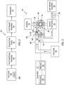
- FIG. 2 illustrates a block diagram depicting the fuel system 34 for the gas turbine engine 22.
- the fuel system 34 of the present disclosure is not limited to use with gas turbine engines (e.g., the gas turbine engine 22) and may also be used with other engines (e.g., rotary engines, piston engines, etc.) for aircraft or aircraft propulsion systems.
- the fuel system 34 of FIG. 2 includes a fuel tank 58, a first fuel pump assembly 60, a second fuel pump 62 (e.g., a high-pressure pump), and a fuel injector assembly 64.
- the fuel tank 58 may include one or more vents 58A such that the contents of the fuel tank 58 are maintained at or near atmospheric pressure.
- the fuel system 34 may include a plurality of fuel tanks 58 (e.g., one or more main fuel tanks and one or more auxiliary fuel tanks), however, the present disclosure is not limited to any particular number or configuration of the fuel tank 58.
- the first fuel pump assembly 60 is configured to draw fuel from the fuel tank 58 and direct the fuel to the second fuel pump 62 at an elevated pressure relative to the fuel tank 58, as will be discussed in further detail.
- the second fuel pump 62 may be configured as a positive displacement pump.
- the second fuel pump 62 is configured to further pressurize the fuel from the first fuel pump assembly 60 and direct the fuel to the fuel injector assembly 64.
- the fuel injector assembly 64 directs the pressurized, metered fuel into the combustor 32 for combustion, as described above.
- FIG. 3 schematically illustrates the first fuel pump assembly 60 and other components of the fuel system 34 in greater detail.
- the first fuel pump assembly 60 of FIG. 3 includes a first fuel pump 66 (e.g., a low-pressure pump), an inlet ejector 68, and an ejector control valve 70.
- the first fuel pump assembly 60 may further include a controller 72.
- the first fuel pump 66 of FIG. 3 is configured as a centrifugal pump.
- the present disclosure is not limited to the foregoing exemplary configuration of the first fuel pump 66.
- the first fuel pump 66 may alternatively be configured as a regenerative pump, a liquid-ring pump, or the like (e.g., a positive displacement pump or a non-positive displacement pump).
- the first fuel pump 66 includes an impeller 74 (sometime referred to as a "wheel") configured for rotation to draw fuel from the fuel tank 58 and direct (e.g., pump) the fuel to the second fuel pump 62.
- the impeller 74 of FIG. 3 is operably connected with a gearbox 76 (e.g., an accessory gearbox) by a shaft 78.
- the gearbox 76 operably connected to one of the output shafts 54 (see FIG. 1 ) to drive the gearbox 76 and, in turn, drive rotation of the impeller 74.
- the second fuel pump 62 may also be operably connected to and driven by the gearbox 76 (e.g., by the shaft 78 or another shaft).
- the present disclosure is not limited to the foregoing exemplary configuration of the impeller 74 with the gearbox 76.
- the impeller 74 may alternatively be driven by an electric motor or another rotational power source of the propulsion system 20 (see FIG. 1 ).
- the first fuel pump 66 includes a fuel inlet 80 and a fuel outlet 82.
- the fuel inlet 80 is connected in fluid communication with the fuel tank 58 by an inlet conduit 84.
- the fuel outlet 82 is connected in fluid communication with the second fuel pump 62 by an outlet conduit 86.
- the inlet conduit 84 and the outlet conduit 86 may be formed by one or more pipes, hoses, tubes, or another suitable fluid conduits, and/or combinations thereof.
- the fuel system 34 may include one or more intermediate fuel components between the fuel tank 58 and the first fuel pump 66 and/or between the first fuel pump 66 and the second fuel pump 62 such as, but not limited to, a fuel filter, a heat exchanger, a fuel flow regulator, a fuel relief valve, or the like.
- the inlet ejector 68 includes an ejector nozzle 88.
- the ejector nozzle 88 is disposed within the inlet conduit 84.
- the ejector nozzle 88 is spaced from the inlet conduit 84 (e.g., walls of the inlet conduit 84) to allow fuel from the fuel tank 58 to flow through the inlet conduit 84 and around the ejector nozzle 88 to the first fuel pump 66.
- the ejector nozzle 88 includes a fuel inlet 90 and a fuel outlet 92.
- the fuel inlet 90 is selectively connected in fluid communication with the outlet conduit 86 by the ejector control valve 70. As shown in FIG.
- the fuel inlet 90 may alternatively be connected in fluid communication with a discharge of the second fuel pump 62 at (e.g., on, adjacent, or proximate) an outlet of the second fuel pump 62.
- the fuel outlet 92 is disposed within the inlet conduit 84.
- the fuel outlet 92 is configured to direct fuel (e.g., from the outlet conduit 86) to the fuel inlet 80 of the first fuel pump 66.
- the ejector control valve 70 is connected in fluid communication with and between the outlet conduit 86 and the ejector nozzle 88.
- the ejector control valve 70 is selectively positionable to direct and control fuel flow to the ejector nozzle 88 from the outlet conduit 86.
- the ejector control valve 70 is positionable in an open position and a closed position. In the open position, the ejector control valve 70 is configured to direct fuel from the outlet conduit 86 to the ejector nozzle 88 (e.g., the fuel inlet 90).
- the ejector control valve 70 In the closed position, the ejector control valve 70 is configured to prevent (e.g., obstruct) all or substantially all fuel flow from the outlet conduit 86 to the ejector nozzle 88 (e.g., the fuel inlet 90).
- the ejector control valve 70 may additionally be positionable in one or more intermediate positions between the open position and the closed position to control (e.g., modulate) a rate of fuel flow from the outlet conduit 86 to the ejector nozzle 88 (e.g., the fuel inlet 90).
- the ejector control valve 70 may be configured as a solenoid valve.
- the ejector control valve 70 may be configured as a hydraulically operated valve, a pneumatically-operated valve, or another suitable valve configuration for facilitating remote operation of the ejector control valve 70.
- the ejector control valve 70 may be remotely controlled by a pilot or other operator to control fuel flow through the ejector nozzle 88.
- the ejector control valve 70 may be controlled by one or more electronic control systems (e.g., the controller 72).
- the controller 72 includes a processor 94 connected in signal communication with memory 96.
- the processor 94 may include any type of computing device, computational circuit, processor(s), CPU, computer, or the like capable of executing a series of instructions that are stored in the memory 96. Instructions can be directly executable or can be used to develop executable instructions. For example, instructions can be realized as executable or non-executable machine code or as instructions in a high-level language that can be compiled to produce executable or non-executable machine code. Further, instructions also can be realized as or can include data. Computer-executable instructions also can be organized in any format, including routines, subroutines, programs, data structures, objects, modules, applications, applets, functions, etc.
- the instructions may include an operating system, and/or executable software modules such as program files, system data, buffers, drivers, utilities, and the like.
- the executable instructions may apply to any functionality described herein to enable the first fuel pump assembly 60 and its components to accomplish the same algorithmically and/or by coordination of the first fuel pump assembly 60 components.
- the controller 72 may be connected in electrical (e.g., signal) communication with the ejector control valve 70 or an actuator (e.g., a hydraulic actuator, a pneumatic actuator, an electro-mechanical actuator, etc.) for the ejector control valve 70 to control a position of the ejector control valve 70.
- an actuator e.g., a hydraulic actuator, a pneumatic actuator, an electro-mechanical actuator, etc.
- the memory 96 may include a single memory device or a plurality of memory devices (e.g., a computer-readable storage device that can be read, written, or otherwise accessed by a general purpose or special purpose computing device), including any processing electronics and/or processing circuitry capable of executing instructions.
- the present disclosure is not limited to any particular type of memory device, which may be non-transitory, and may include read-only memory, random access memory, volatile memory, non-volatile memory, static memory, dynamic memory, flash memory, cache memory, volatile or non-volatile semiconductor memory, optical disk storage, magnetic disk storage, magnetic tape, other magnetic storage devices, or any other medium capable of storing one or more instructions, and/or any device that stores digital information.
- the memory device(s) may be directly or indirectly coupled to the controller 72.
- the controller 72 may include, or may be in communication with, an input device that enables a user to enter data and/or instructions, and may include, or be in communication with, an output device configured, for example to display information (e.g., a visual display or a printer), or to transfer data, etc. Communications between the controller 72 and other electrical and/or electronic components (e.g., controllers, sensors, etc.) may be via a hardwire connection or via a wireless connection.
- portions of the controller 72 may assume various forms (e.g., digital signal processor, analog device, etc.) capable of performing the functions described herein.
- the controller 72 may form or otherwise be part of an electronic engine controller (EEC) for the gas turbine engine 22.
- EEC electronic engine controller
- the EEC may control aspects of the gas turbine engine 22 operation such as, but not limited to, fuel flow, stator vane position (e.g., variable compressor inlet guide vane (IGV) position), compressor air bleed valve position, shaft (e.g., first shaft 42 and/or second shaft 48) torque and/or rotation speed, etc. so as to control an engine power or performance of the gas turbine engine 22.
- the EEC may modulate fuel flow to the combustor 32 to obtain a desired output power of the gas turbine engine 22.
- the EEC may be part of a full authority digital engine control (FADEC) system for the propulsion system 20.
- FADEC full authority digital engine control
- the controller 72 may be connected in signal communication with one or more sensors of the propulsion system 20, the gas turbine engine 22, the fuel system 34, and/or the aircraft on which the propulsion system 20 is installed.
- the controller 72 of FIG. 3 is connected in signal communication with a pressure sensor 98 (e.g., a pressure transducer) at (e.g., on, adjacent, or proximate) a fuel outlet of the second fuel pump 62 to measure the second fuel pump 62 discharge pressure.
- a pressure sensor 98 e.g., a pressure transducer
- the controller 72 may be configured to measurement signals (e.g., from the one or more sensors) for operational parameters of the propulsion system 20, the gas turbine engine 22, the fuel system 34, and/or the aircraft on which the propulsion system 20 is installed, which operational parameters may be representative of, proportional to, or otherwise useful for deriving a pressure of the fuel at (e.g., on, adjacent, or proximate) the fuel inlet 80.
- the controller 72 may receive or calculate operational parameters such as, but not limited to gas turbine engine 22 power, altitude, gas turbine engine 22 air pressure (e.g., low-pressure compressor 24A and/or high-pressure compressor 24B outlet pressure), fuel temperature within the fuel system 34, second fuel pump 62 discharge pressure, and/or other sensor output or calculated values which may be used by the controller 72 to control the operation of components of the first fuel pump assembly 60 (e.g., the ejector control valve 70).
- operational parameters such as, but not limited to gas turbine engine 22 power, altitude, gas turbine engine 22 air pressure (e.g., low-pressure compressor 24A and/or high-pressure compressor 24B outlet pressure), fuel temperature within the fuel system 34, second fuel pump 62 discharge pressure, and/or other sensor output or calculated values which may be used by the controller 72 to control the operation of components of the first fuel pump assembly 60 (e.g., the ejector control valve 70).
- the first fuel pump 66 (e.g., the impeller 74) operates to draw fuel from the fuel tank 58, as described above.
- the fuel stored within the fuel tank 58 may, over time, absorb and become saturated with air (e.g., mainly nitrogen, oxygen, and argon).
- air e.g., mainly nitrogen, oxygen, and argon.
- a reduction in fluid pressure of the fuel as the fuel is drawn from the fuel tank 58 toward the first fuel pump 66 may cause the some or all of the air absorbed by the fuel to evolve from the fuel.
- the amount of air evolution depends, for example, upon the reduction in pressure and the initial air saturation level of the fuel.
- An excessive amount of air evolution from the fuel may cause the first fuel pump 66 to supply (e.g., pump) insufficient liquid fuel to the second fuel pump 62, and hence to the fuel injector assembly 64, thereby preventing the engine 22 from maintaining a correct (e.g., commanded) operating power condition.
- the first fuel pump 66 to supply (e.g., pump) insufficient liquid fuel to the second fuel pump 62, and hence to the fuel injector assembly 64, thereby preventing the engine 22 from maintaining a correct (e.g., commanded) operating power condition.
- the inlet ejector 68 mixes fuel drawn from the outlet conduit 86 (e.g., downstream of the first fuel pump 66) with fuel drawn from the fuel tank 58 in the inlet conduit 84 before this fuel reaches the fuel inlet 80 of the first fuel pump 66.
- the fuel mixing effected by the inlet ejector 68 breaks down large air bubbles entrained in the fuel being drawn from the fuel tank 58 to reduce the V/L ratio of the fuel and increases the fluid pressure of the fuel entering the first fuel pump 66 (e.g., the fuel inlet 80).
- the reduction in fluid pressure of the fuel as the fuel is drawn from the fuel tank 58 is, in part, a function of the fuel flow rate (e.g., the engine burn flow) through the fuel system 34 and a difference in elevation between a free surface of fuel within the fuel tank 58 and the inlet conduit 84.
- the inlet ejector 68 is primarily beneficial for reducing the fuel V/L ratio of the fuel and increasing the fluid pressure of the fuel at higher gas turbine engine 22 power levels where the high fuel flow rate tends to significantly reduce the fluid pressure of the fuel drawn from the fuel tank 58.
- the operation of the inlet ejector 68 can detrimentally introduce heated fuel from the first fuel pump 66 discharge (e.g., the fuel outlet 82) into the relatively lower pressure and cooler fuel in the inlet conduit 84, thereby causing the fuel to boil (e.g., flash) prior to entering the first fuel pump 66.
- the ejector control valve 70 is configured to direct and control fuel flow from the outlet conduit 86 through the inlet ejector 68 (e.g., the ejector nozzle 88).
- the ejector control valve 70 may be positioned in the open position to direct fuel through the inlet ejector 68 to break up air bubbles evolved from the fuel within the inlet conduit 84.
- the ejector control valve 70 may be positioned in the closed position or an intermediate position to prevent or reduce the flow of fuel into and through the inlet ejector 68.
- the controller 72 may control a position of the ejector control valve 70 to control a flow rate of the fuel through the inlet ejector 68 based on one or more operational parameters of the gas turbine engine 22 and/or the fuel system 34. For example, the controller 72 may control the position of the ejector control valve 70 using the second fuel pump 62 discharge pressure (e.g., from the pressure sensor 98). The controller 72 may control the ejector control valve 70 in the open position where the second fuel pump 62 discharge pressure is greater than or equal to a first pressure threshold. The controller 72 may control the ejector control valve 70 in the shut position where the second fuel pump 62 discharge pressure is less than or equal to a second pressure threshold which is less than the first pressure threshold. The controller 72 may control the ejector control valve 70 in an intermediate position where the second fuel pump 62 discharge pressure is between the first pressure threshold and the second pressure threshold, for example, to modulate fuel flow directed through the inlet ejector 68.
- the controller 72 may control the position of the e
- any one of these structures may describe the operations as a sequential process, many of the operations can be performed in parallel or concurrently.
- the order of the operations may be rearranged.
- a process may correspond to a method, a function, a procedure, a subroutine, a subprogram, etc.
Landscapes
- Engineering & Computer Science (AREA)
- Chemical & Material Sciences (AREA)
- Combustion & Propulsion (AREA)
- Mechanical Engineering (AREA)
- General Engineering & Computer Science (AREA)
- Jet Pumps And Other Pumps (AREA)
- Physics & Mathematics (AREA)
- Fluid Mechanics (AREA)
Applications Claiming Priority (1)
| Application Number | Priority Date | Filing Date | Title |
|---|---|---|---|
| US18/387,258 US20250146461A1 (en) | 2023-11-06 | 2023-11-06 | Gas Turbine Engine Fuel System for an Aircraft Propulsion System |
Publications (2)
| Publication Number | Publication Date |
|---|---|
| EP4549717A2 true EP4549717A2 (fr) | 2025-05-07 |
| EP4549717A3 EP4549717A3 (fr) | 2025-08-06 |
Family
ID=93430775
Family Applications (1)
| Application Number | Title | Priority Date | Filing Date |
|---|---|---|---|
| EP24210983.3A Pending EP4549717A3 (fr) | 2023-11-06 | 2024-11-05 | Système de carburant de moteur à turbine à gaz pour système de propulsion d'aéronef |
Country Status (2)
| Country | Link |
|---|---|
| US (1) | US20250146461A1 (fr) |
| EP (1) | EP4549717A3 (fr) |
Family Cites Families (5)
| Publication number | Priority date | Publication date | Assignee | Title |
|---|---|---|---|---|
| US3841089A (en) * | 1973-02-20 | 1974-10-15 | Ltv Aerospace Corp | Fuel reclaiming system |
| US5896737A (en) * | 1997-06-16 | 1999-04-27 | United Technologies Corporation | Combined pressure regulating and fuel flow system |
| US9091212B2 (en) * | 2013-03-27 | 2015-07-28 | Hamilton Sundstrand Corporation | Fuel and actuation system for gas turbine engine |
| US10443503B2 (en) * | 2015-03-27 | 2019-10-15 | Pratt & Whitney Canada Corp. | Fuel system for a gas turbine engine |
| US20210079848A1 (en) * | 2019-03-20 | 2021-03-18 | United Technologies Corporation | Secondary fuel flow demand fuel pumping system |
-
2023
- 2023-11-06 US US18/387,258 patent/US20250146461A1/en active Pending
-
2024
- 2024-11-05 EP EP24210983.3A patent/EP4549717A3/fr active Pending
Also Published As
| Publication number | Publication date |
|---|---|
| US20250146461A1 (en) | 2025-05-08 |
| EP4549717A3 (fr) | 2025-08-06 |
Similar Documents
| Publication | Publication Date | Title |
|---|---|---|
| GB1320530A (en) | Gas turbine engine | |
| EP4527744A1 (fr) | Système de détection de fuite d'hydrogène pour un système de propulsion d'aéronef | |
| EP3315743B1 (fr) | Système de gestion de poussée pour moteurs à turbopropulseur | |
| US10711701B2 (en) | Manual bowed rotor and full override | |
| CN112302808A (zh) | 使用电机的压缩系统的主动稳定性控制 | |
| US8800295B2 (en) | Device and a method for regulating a turbine engine, and an aircraft | |
| EP4549717A2 (fr) | Système de carburant de moteur à turbine à gaz pour système de propulsion d'aéronef | |
| EP4296493A1 (fr) | Système de pompe à carburant double pour aéronef | |
| EP4459157A1 (fr) | Capteur de couple pour ensemble de transmission de système de propulsion d'aéronef | |
| EP4464873A1 (fr) | Ensemble de commande de freinage pour moteur à turbine à gaz d'aéronef et son procédé d'utilisation | |
| Catana et al. | Gas Turbine Engine Starting Applicated on TV2-117 Turboshaft | |
| US20250084796A1 (en) | Engine assembly for an aircraft propulsion system | |
| US12152531B1 (en) | Transmission assembly for an aircraft engine assembly and architecture for controlling same | |
| EP3808957B1 (fr) | Un contrôleur de moteur électronique pour un moteur à turbine à gaz configuré pour être connecté à une électrovanne | |
| US12509236B1 (en) | Control assembly for aircraft propulsion systems | |
| EP4506550A1 (fr) | Systèmes et méthodes pour identifier une acceleration insuffisante du démarreur pour un moteur d'aéronef | |
| EP4733562A2 (fr) | Systèmes et procédés de fonctionnement d'un moteur d'aéronef à l'aide de multiples types de carburant | |
| EP4733563A1 (fr) | Systèmes et procédés de fonctionnement d'un moteur d'aéronef à l'aide de multiples types de carburant | |
| EP4733564A1 (fr) | Systèmes et procédés de fonctionnement d'un moteur d'aéronef à l'aide de multiples types de carburant | |
| EP4733560A2 (fr) | Systèmes et procédés de fonctionnement d'un moteur d'aéronef à l'aide de multiples types de carburant | |
| EP4733565A2 (fr) | Systèmes et procédés de fonctionnement d'un moteur d'aéronef à l'aide de multiples types de carburant | |
| EP4700218A2 (fr) | Système d'injection d'eau pour augmenter la performance et la durabilité avec réservoir d'eau sélectivement utilisé | |
| US20240410321A1 (en) | System and method for controlling engines of a multi-engine aircraft engine assembly | |
| US20260117710A1 (en) | Systems and methods for operating an aircraft engine using multiple fuel types | |
| US20250341190A1 (en) | Partial-admission turbine assembly for an aircraft and method for controlling same |
Legal Events
| Date | Code | Title | Description |
|---|---|---|---|
| PUAI | Public reference made under article 153(3) epc to a published international application that has entered the european phase |
Free format text: ORIGINAL CODE: 0009012 |
|
| STAA | Information on the status of an ep patent application or granted ep patent |
Free format text: STATUS: THE APPLICATION HAS BEEN PUBLISHED |
|
| AK | Designated contracting states |
Kind code of ref document: A2 Designated state(s): AL AT BE BG CH CY CZ DE DK EE ES FI FR GB GR HR HU IE IS IT LI LT LU LV MC ME MK MT NL NO PL PT RO RS SE SI SK SM TR |
|
| PUAL | Search report despatched |
Free format text: ORIGINAL CODE: 0009013 |
|
| AK | Designated contracting states |
Kind code of ref document: A3 Designated state(s): AL AT BE BG CH CY CZ DE DK EE ES FI FR GB GR HR HU IE IS IT LI LT LU LV MC ME MK MT NL NO PL PT RO RS SE SI SK SM TR |
|
| RIC1 | Information provided on ipc code assigned before grant |
Ipc: F02C 7/236 20060101AFI20250703BHEP Ipc: F02C 7/232 20060101ALI20250703BHEP |
|
| STAA | Information on the status of an ep patent application or granted ep patent |
Free format text: STATUS: REQUEST FOR EXAMINATION WAS MADE |
|
| 17P | Request for examination filed |
Effective date: 20260206 |