EP4549725A1 - Raccord - Google Patents
Raccord Download PDFInfo
- Publication number
- EP4549725A1 EP4549725A1 EP24208777.3A EP24208777A EP4549725A1 EP 4549725 A1 EP4549725 A1 EP 4549725A1 EP 24208777 A EP24208777 A EP 24208777A EP 4549725 A1 EP4549725 A1 EP 4549725A1
- Authority
- EP
- European Patent Office
- Prior art keywords
- impeller
- fitting
- main passage
- fitting according
- fluid
- Prior art date
- Legal status (The legal status is an assumption and is not a legal conclusion. Google has not performed a legal analysis and makes no representation as to the accuracy of the status listed.)
- Pending
Links
Images





Classifications
-
- F—MECHANICAL ENGINEERING; LIGHTING; HEATING; WEAPONS; BLASTING
- F03—MACHINES OR ENGINES FOR LIQUIDS; WIND, SPRING, OR WEIGHT MOTORS; PRODUCING MECHANICAL POWER OR A REACTIVE PROPULSIVE THRUST, NOT OTHERWISE PROVIDED FOR
- F03B—MACHINES OR ENGINES FOR LIQUIDS
- F03B17/00—Other machines or engines
- F03B17/06—Other machines or engines using liquid flow with predominantly kinetic energy conversion, e.g. of swinging-flap type, "run-of-river", "ultra-low head"
-
- F—MECHANICAL ENGINEERING; LIGHTING; HEATING; WEAPONS; BLASTING
- F16—ENGINEERING ELEMENTS AND UNITS; GENERAL MEASURES FOR PRODUCING AND MAINTAINING EFFECTIVE FUNCTIONING OF MACHINES OR INSTALLATIONS; THERMAL INSULATION IN GENERAL
- F16L—PIPES; JOINTS OR FITTINGS FOR PIPES; SUPPORTS FOR PIPES, CABLES OR PROTECTIVE TUBING; MEANS FOR THERMAL INSULATION IN GENERAL
- F16L29/00—Joints with fluid cut-off means
- F16L29/002—Joints with fluid cut-off means joints with taps
-
- G—PHYSICS
- G01—MEASURING; TESTING
- G01D—MEASURING NOT SPECIALLY ADAPTED FOR A SPECIFIC VARIABLE; ARRANGEMENTS FOR MEASURING TWO OR MORE VARIABLES NOT COVERED IN A SINGLE OTHER SUBCLASS; TARIFF METERING APPARATUS; MEASURING OR TESTING NOT OTHERWISE PROVIDED FOR
- G01D11/00—Component parts of measuring arrangements not specially adapted for a specific variable
-
- H—ELECTRICITY
- H02—GENERATION; CONVERSION OR DISTRIBUTION OF ELECTRIC POWER
- H02K—DYNAMO-ELECTRIC MACHINES
- H02K7/00—Arrangements for handling mechanical energy structurally associated with dynamo-electric machines, e.g. structural association with mechanical driving motors or auxiliary dynamo-electric machines
- H02K7/18—Structural association of electric generators with mechanical driving motors, e.g. with turbines
- H02K7/1807—Rotary generators
- H02K7/1823—Rotary generators structurally associated with turbines or similar engines
-
- F—MECHANICAL ENGINEERING; LIGHTING; HEATING; WEAPONS; BLASTING
- F05—INDEXING SCHEMES RELATING TO ENGINES OR PUMPS IN VARIOUS SUBCLASSES OF CLASSES F01-F04
- F05B—INDEXING SCHEME RELATING TO WIND, SPRING, WEIGHT, INERTIA OR LIKE MOTORS, TO MACHINES OR ENGINES FOR LIQUIDS COVERED BY SUBCLASSES F03B, F03D AND F03G
- F05B2220/00—Application
- F05B2220/20—Application within closed fluid conduits, e.g. pipes
-
- F—MECHANICAL ENGINEERING; LIGHTING; HEATING; WEAPONS; BLASTING
- F05—INDEXING SCHEMES RELATING TO ENGINES OR PUMPS IN VARIOUS SUBCLASSES OF CLASSES F01-F04
- F05B—INDEXING SCHEME RELATING TO WIND, SPRING, WEIGHT, INERTIA OR LIKE MOTORS, TO MACHINES OR ENGINES FOR LIQUIDS COVERED BY SUBCLASSES F03B, F03D AND F03G
- F05B2220/00—Application
- F05B2220/60—Application making use of surplus or waste energy
- F05B2220/602—Application making use of surplus or waste energy with energy recovery turbines
-
- F—MECHANICAL ENGINEERING; LIGHTING; HEATING; WEAPONS; BLASTING
- F05—INDEXING SCHEMES RELATING TO ENGINES OR PUMPS IN VARIOUS SUBCLASSES OF CLASSES F01-F04
- F05B—INDEXING SCHEME RELATING TO WIND, SPRING, WEIGHT, INERTIA OR LIKE MOTORS, TO MACHINES OR ENGINES FOR LIQUIDS COVERED BY SUBCLASSES F03B, F03D AND F03G
- F05B2220/00—Application
- F05B2220/70—Application in combination with
- F05B2220/706—Application in combination with an electrical generator
- F05B2220/7068—Application in combination with an electrical generator equipped with permanent magnets
-
- F—MECHANICAL ENGINEERING; LIGHTING; HEATING; WEAPONS; BLASTING
- F05—INDEXING SCHEMES RELATING TO ENGINES OR PUMPS IN VARIOUS SUBCLASSES OF CLASSES F01-F04
- F05B—INDEXING SCHEME RELATING TO WIND, SPRING, WEIGHT, INERTIA OR LIKE MOTORS, TO MACHINES OR ENGINES FOR LIQUIDS COVERED BY SUBCLASSES F03B, F03D AND F03G
- F05B2270/00—Control
- F05B2270/80—Devices generating input signals, e.g. transducers, sensors, cameras or strain gauges
Definitions
- the present invention relates to a fitting for fluids, for example compressed air, comprising impeller means drivable by the pressurized fluid crossing the fitting to generate electrical energy.
- Pneumatic or hydraulic devices in particular valves for regulating the flow of a fluid, are known to be provided with means for recovering kinetic and/or potential energy that would otherwise be wasted.
- These energy recovery means generally comprise a rotating element and diffusing means adapted to direct the fluid towards the recovery means.
- a valve of this type is for example described in WO2014132187A2 .
- Hydraulic devices have already been proposed, for example in domestic thermal and sanitary installations, wherein the water circulating within a component of the system, such as a pipe, a tap, a shower head, or the like, actuates a turbine that powers an electronic device in order to produce a light and/or sound effect for example.
- the object of the present invention is to propose a fitting for a pressurized fluid circuit capable of generating electrical energy, for example for powering sensors, whilst satisfying the aforementioned requirements for compactness, robustness, design simplicity, and insulation.
- reference numeral 1 indicates a fitting for a pressurized fluid circuit, for example a pneumatic circuit.
- the term "fitting” does not necessarily have to be understood in a strict sense to be a component which has the sole function of sealingly connecting two tubes or ducts of a pressurized fluid circuit (although the present invention, due to the features of compactness and robustness thereof, lends itself particularly to being applied to such a component), but may also comprise other components or parts of components wherein a pressurized fluid flows from a first passage (which may be defined as an inlet passage) to at least one second passage (which may be defined as an outlet passage), amongst which other functional elements may also be present, for example a shutter.
- a first passage which may be defined as an inlet passage
- second passage which may be defined as an outlet passage
- conjunction references e.g. fixed, coupled, connected, and the like
- the conjunction references must be interpreted broadly and may include intermediate elements between a connection of elements and a relative movement between elements.
- the conjunction references do not therefore necessarily imply that two elements are directly connected in a fixed relationship with one another.
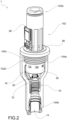
- fitting 1 comprises a fitting body 10 crossed by a main passage 11 for a pressurized fluid, such as compressed air.
- the main passage 11 extends between a fluid inlet opening 12 and a fluid outlet opening 14.
- fitting body 10 extends mainly along a fitting axis Y, the inlet opening 12, and the outlet opening 14 being aligned with one another along said fitting axis Y.
- fitting 1 is an inline fitting that extends in the same direction as the axis of an incoming tube and consequently also the axis of an outlet tube (not shown).
- the invention may however be implemented in other fitting layouts, such as "L” or "T” fittings.
- connection cartridges 60 for example of the super-fast type, for connecting to the respective tubes thereof.
- An impeller 16 is housed in the fitting body 10, which impeller is rotatably drivable by the pressurized fluid crossing the fitting body 10.
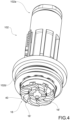
- the impeller 16 is of the radial type, i.e., it is provided with a plurality of blades 16', preferably curved blades, extending mainly in a radial direction from the center of the impeller, which coincides with the rotation axis X thereof, towards the outside.
- the impeller 16 has the rotation axis X coaxial to at least one portion of the main passage 11.
- the impeller 16 may have the rotation axis X orthogonal to the main passage 11.
- the magnets 18 are distributed circumferentially so as to form a magnet ring 180.
- the magnet seats 182 are obtained coaxially to the rotation axis X of the impeller 16, and preferably are axially superimposed on the blades 16' of the impeller 16, in such a way as to encompass the radial dimensions of the fitting.
- a plurality of coils 20 is also housed within the fitting body 10.
- the coils 20 are distributed circumferentially so as to form a coil ring 200 magnetically coupled to the magnet ring 180.
- an electric current is generated in the electrical windings of the coils 20 which has an intensity sufficient to be used to power electronic devices, as will be described below.
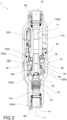
- the electric current generated by the coils 20 powers at least one sensor 22 integrated into the fitting body 10, or otherwise encapsulated in a protective casing 220 fastened to the fitting body 10 ( Figure 3 ).
- sensor 22 is suitable for detecting one or more of temperature, humidity, fluid pressure, flow rate.
- the electric current generated by the coils 20 also powers an electronic data transmission unit 24, such as a microprocessor unit.
- the electric current generated by the coils 20 also powers at least one LED, for example to indicate when the impeller produces energy.
- the electronic data transmission unit 24 is operatively connected to the at least one sensor 22 and is configured to wirelessly transmit data received from the at least one sensor 22.
- the data transmission unit 24 is configured to transmit, for example by means of a radio transmitter, a wireless presence signal when it receives voltage, i.e., it is powered by the current generated by the coils 20.
- a wireless presence signal is transmitted to a network or to a receiving device according to a predetermined communication protocol.
- the rectified wave suitably filtered and limited in amplitude, supplies a part of the circuit configured to generate the voltage necessary for the correct operation of the micro-controller 24.
- Zener diode 30 Although this solution means that part of the energy produced by the impeller that is above the activation threshold of the Zener diode 30 is not used, a Zener diode is nevertheless chosen in such a way that the available energy is always sufficient to ensure the correct functioning of the components of the electronic circuit.
- the electronic circuit 300 is suitable for detecting fluid flow characteristics.
- the electronic circuit 300 comprises a rectified voltage reading circuit 32 and a half-wave voltage reading circuit 34 which, by means of a voltage splitter, allow the microprocessor 24 to read the rectified and half-wave voltages.
- actuators for manipulating the flow or for indicating the state of the device and the physical quantities monitored thereby.
- All of the information collected by the sensors, calculated data and control signals for the actuators are transmitted via wireless technology (for example Bluetooth Low Energy), integrated into the microprocessor 24.
- wireless technology for example Bluetooth Low Energy
- This technology allows for communication with an external device and therefore one or more users to monitor, configure and control the connection.
- the coils 20 are arranged in such a way as to have their respective axes parallel to the rotation axis X of the impeller.
- the electrical terminals 202 of the coils 20 may also be oriented parallel to the rotation axis X of the impeller. This also allows the coils 20 to be connected in series with one another by means of an electronic coil connection board 36 with an annular shape, supported by the fitting body 10 coaxially to the rotation axis X of the impeller.
- the coils 20 could also be arranged in this way, i.e., with the relative axes orthogonal to the rotation axis of the impeller.
- This electronic coil connection board 36 is in turn connected to a main electronic board 38, whereupon the electronic circuit 300 described above is obtained and whereupon at least one sensor 22 may be mounted.
- This main electronic board 38 may be arranged perpendicularly with respect to the electronic coil connection board 36, i.e., lying in a plane parallel to the rotation axis X of the impeller 16.
- a plurality of nozzles 40 for supplying the impeller 16 is obtained in the fitting body 10.
- said nozzles 40 extend radially from the main passage 11.
- four nozzles 40 are obtained in the fitting body 10, spaced apart by an angle of 90° and perpendicular to the rotation axis X of the impeller 16.
- the nozzles 40 emerge between the curved radial blades 16' of the impeller 16.
- the impeller body 16 integrates a ferromagnetic ring 162, i.e., a steel plate, suitable for amplifying the magnetic field.
- the impeller 16 is mounted, for the rotation and guidance thereof, upon at least one impeller support 164 coupled to the fitting body 10.
- the impeller support 164 consists of a ball bearing or a sliding bush.
- the impeller 16 is mounted with clearance on the fitting body 10 so that, when driven in rotation, an annular air cushion is formed between the impeller 16 and the fitting body 10.
- the air cushion allows the impeller to rotate suspended in the fitting body, without contact with the body and therefore without friction.
- the impeller 16 is in fluid communication with the outlet opening 14 of the fluid, in such a way that the portion of fluid flow that enters the supply nozzles 40 and supplies the impeller 16 is reconveyed towards the outlet opening 14.
- the impeller 16 is in fluid communication with a distal segment of the main passage 11, which ends with the outlet opening 14.
- the partialization of the flow entering the fitting for supplying the impeller has several advantages.
- the energy taken from the fluid flow entering the fitting for feeding the impeller is a fraction of the total energy, so that most of the flow remains available for the final application (e.g., the actuation of a pneumatic cylinder).
- the ratio between the flow circulating in the impeller and the flow flowing in the main passage 11 depends upon the fact that the path of the impeller supply fluid has numerous pressure drops, in particular caused by the radial nozzles, which have a very small diameter and force the main flow to deviate abruptly, and by the impeller itself, which channels the flow by extracting mechanical work.
- the impeller 16 is housed within an impeller chamber 50 fluidly connected to the main passage 11 through a return passage 52.
- the supply nozzles 40, the impeller chamber 50, and the return passage 52 in practice form a secondary, or bypass, passage connected in parallel to the main passage 11.
- the return passage 52 flows into the main passage 11 in proximity to the outlet opening 14, or in any case into a distal portion of the main passage 11 between the supply nozzles 40 and the outlet opening 14.
- the fitting body 10 comprises a first body section 102 and a second body section 104, arranged in succession along the direction of flow of the fluid crossing the fitting.
- a first section 11a of the main passage 11 is formed in the first body section 102.
- the first body section 102 extends between a first proximal portion 102a, which forms the inlet opening 12, and a first distal portion 102b.
- the coil ring 200 is supported by this first body section 102.
- the second body section 104 In the second body section 104, a second portion 11b of the main passage 11 is obtained.
- the second body section 104 extends between a second proximal portion 104a and a second distal portion 104b, which forms the outlet opening 14.
- the first section 102 of the fitting body 10 is partially and axially inserted into the second section 104 of the fitting body 10.
- the second proximal portion 104a coaxially surrounds the first distal portion 102b so as to form, with the first distal portion 102b, the impeller chamber 50 wherein the impeller 16 is housed.
- the impeller chamber 50 is in fluid communication with the second section 11b of the main passage 11.
- the impeller chamber 50 is in the form of a cup, with a larger part accommodating the impeller and a part that progressively narrows and flows into the second portion 11b of the main passage 11.
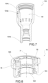
- the first distal portion 102b of the first section 102 of the fitting body 10 forms a peripheral flange 102c having a threaded outer surface 102d.
- the second proximal portion 104a of the second section 104 of the fitting body forms an internally threaded collar 104c suitable for screwing onto the peripheral flange 102c.
- a sealing ring 42 may be interposed between the two connecting elements.
- the inner wall of the peripheral flange 102c radially delimits an annular coil seat 204 wherein the coil ring 200 is housed ( Figure 6 ).
- the first section 102 of the fitting body 10 is in turn formed by the axial coupling between a first section first element 1022 (proximal to the direction of fluid flow within the fitting), and a first section second element 1024 (distal element).
- the nozzles 40 for supplying the impeller 26 may be obtained.
- the energy required to start the impeller from standstill is in fact greater than that necessary to keep it in rotation, once started.
- the one-way device 70 is calibrated so as to open when a minimum pressure difference threshold ( ⁇ P) is reached between the inlet opening and the outlet opening of the fitting. Until such threshold is reached, all of the fluid entering the inlet opening 12 impinges upon the impeller 26, thus facilitating the start-up thereof.
- ⁇ P minimum pressure difference threshold
- the one-way device 70 consists of a one-way valve.
- the one-way valve 70 is housed in the second body section 104 and has an elastically pushed shutter element 72, for example by a helical spring 74, in a closed position of the distal end of the first section 11a of the main passage 11.
- the shutter element 72 is supported by a hollow valve body 76, provided with side openings 78, so as to allow the portion of the fluid flow that feeds the impeller 16 to flow towards the outlet opening 14 even when the one-way valve 70 is in the closed position of the main passage 11.
- the one-way device 70 comprises a duckbill valve, which is a rubber element that only allows the passage of air, in one direction, when a certain pressure differential between the inlet and outlet is exceeded.
- the one-way device 70 also makes it possible to limit the drop in pressure and to ensure an adequate flow rate at the outlet of the fitting.
Landscapes
- Engineering & Computer Science (AREA)
- Power Engineering (AREA)
- General Engineering & Computer Science (AREA)
- Mechanical Engineering (AREA)
- Physics & Mathematics (AREA)
- General Physics & Mathematics (AREA)
- Chemical & Material Sciences (AREA)
- Combustion & Propulsion (AREA)
- Measuring Volume Flow (AREA)
- Pipe Accessories (AREA)
- Connection Of Motors, Electrical Generators, Mechanical Devices, And The Like (AREA)
Applications Claiming Priority (2)
| Application Number | Priority Date | Filing Date | Title |
|---|---|---|---|
| IT202300022836 | 2023-10-31 | ||
| IT202400023115 | 2024-10-17 |
Publications (1)
| Publication Number | Publication Date |
|---|---|
| EP4549725A1 true EP4549725A1 (fr) | 2025-05-07 |
Family
ID=93211760
Family Applications (1)
| Application Number | Title | Priority Date | Filing Date |
|---|---|---|---|
| EP24208777.3A Pending EP4549725A1 (fr) | 2023-10-31 | 2024-10-24 | Raccord |
Country Status (4)
| Country | Link |
|---|---|
| US (1) | US20250141305A1 (fr) |
| EP (1) | EP4549725A1 (fr) |
| JP (1) | JP2025076376A (fr) |
| CN (1) | CN119957359A (fr) |
Citations (5)
| Publication number | Priority date | Publication date | Assignee | Title |
|---|---|---|---|---|
| DE9290093U1 (de) * | 1991-07-20 | 1994-03-03 | Cosmos Entwicklungs- und Forschungsanstalt, Vaduz | Sanitärarmatur |
| US20040195840A1 (en) * | 1999-10-05 | 2004-10-07 | Baarman David W. | Miniature hydro-power generation system |
| DE102010009215A1 (de) * | 2010-02-25 | 2011-08-25 | Guzman, Cristobal, 74363 | Strömungsregler für Flüssigkeiten mit Energieversorgung über die Strömung |
| US20110232785A1 (en) * | 2010-03-26 | 2011-09-29 | Hiroshi Takahashi | Oil storing device and engine having the same |
| WO2014132187A2 (fr) | 2013-02-27 | 2014-09-04 | Gattavari Claudio Angelo | Soupape de commande à récupération d'énergie |
-
2024
- 2024-10-24 EP EP24208777.3A patent/EP4549725A1/fr active Pending
- 2024-10-28 US US18/928,356 patent/US20250141305A1/en active Pending
- 2024-10-29 JP JP2024189568A patent/JP2025076376A/ja active Pending
- 2024-10-31 CN CN202411540513.1A patent/CN119957359A/zh active Pending
Patent Citations (5)
| Publication number | Priority date | Publication date | Assignee | Title |
|---|---|---|---|---|
| DE9290093U1 (de) * | 1991-07-20 | 1994-03-03 | Cosmos Entwicklungs- und Forschungsanstalt, Vaduz | Sanitärarmatur |
| US20040195840A1 (en) * | 1999-10-05 | 2004-10-07 | Baarman David W. | Miniature hydro-power generation system |
| DE102010009215A1 (de) * | 2010-02-25 | 2011-08-25 | Guzman, Cristobal, 74363 | Strömungsregler für Flüssigkeiten mit Energieversorgung über die Strömung |
| US20110232785A1 (en) * | 2010-03-26 | 2011-09-29 | Hiroshi Takahashi | Oil storing device and engine having the same |
| WO2014132187A2 (fr) | 2013-02-27 | 2014-09-04 | Gattavari Claudio Angelo | Soupape de commande à récupération d'énergie |
Also Published As
| Publication number | Publication date |
|---|---|
| CN119957359A (zh) | 2025-05-09 |
| US20250141305A1 (en) | 2025-05-01 |
| JP2025076376A (ja) | 2025-05-15 |
Similar Documents
| Publication | Publication Date | Title |
|---|---|---|
| JP7592045B2 (ja) | ロータを支承し、当該ロータを磁気的に軸線方向に位置決めするための磁石を有するポンプ、及びこれに関連する方法 | |
| US7919877B2 (en) | Faucet generator | |
| EP2016233B1 (fr) | Système intégré pour dispositifs hydro-thermo-sanitaires | |
| EP3631376B1 (fr) | Débitmètre à turbine, ensemble, et procédé de mesure d'au moins une caractéristique d'écoulement | |
| US20090188995A1 (en) | Faucet apparatus | |
| US20080284175A1 (en) | Self-Powered Non-Contact Water Appliance | |
| TW201133171A (en) | Flow controller | |
| US11466691B2 (en) | Fault protection for a pump-motor assembly | |
| JP2008163731A (ja) | 水栓 | |
| CN102292548A (zh) | 用于提高泵中压缩空气效率的方法 | |
| JP2007512940A (ja) | 電源内蔵型小型液体処理システム | |
| US9027844B2 (en) | Water delivery system and valve for a sink | |
| JP2009047162A (ja) | 水栓用発電機 | |
| US20250141305A1 (en) | Fitting | |
| US20140312253A1 (en) | Compact self powered and automated attachment to a fluid system | |
| WO2005024537A1 (fr) | Regulation d'un fluide | |
| JP4554634B2 (ja) | フランジ結合部材およびそれを使用したパイプラインの異常検出装置 | |
| JP3605631B2 (ja) | 電磁式給水弁装置 | |
| KR102555772B1 (ko) | 하베스팅에 의한 실시간 모니터링 기능을 가지는 원심펌프 및 이를 적용한 부스터 펌프 시스템 | |
| EP1764586B1 (fr) | Dispositif d'interruption du contrôle de circulation des chauffe-eau muraux à allumage au gaz | |
| JP2014163747A (ja) | 流量検出装置、流体供給装置 | |
| JP7477436B2 (ja) | 水車式流量制御装置 | |
| WO2015198325A1 (fr) | Accessoire automatisé et auto-alimenté compact fixé à un système de fluide | |
| JP2009027892A (ja) | 水栓用発電機 | |
| KR102467699B1 (ko) | 동작 상태 감지장치를 포함하는 개폐장치 |
Legal Events
| Date | Code | Title | Description |
|---|---|---|---|
| PUAI | Public reference made under article 153(3) epc to a published international application that has entered the european phase |
Free format text: ORIGINAL CODE: 0009012 |
|
| STAA | Information on the status of an ep patent application or granted ep patent |
Free format text: STATUS: THE APPLICATION HAS BEEN PUBLISHED |
|
| AK | Designated contracting states |
Kind code of ref document: A1 Designated state(s): AL AT BE BG CH CY CZ DE DK EE ES FI FR GB GR HR HU IE IS IT LI LT LU LV MC ME MK MT NL NO PL PT RO RS SE SI SK SM TR |
|
| STAA | Information on the status of an ep patent application or granted ep patent |
Free format text: STATUS: REQUEST FOR EXAMINATION WAS MADE |
|
| 17P | Request for examination filed |
Effective date: 20251031 |
|
| GRAP | Despatch of communication of intention to grant a patent |
Free format text: ORIGINAL CODE: EPIDOSNIGR1 |
|
| STAA | Information on the status of an ep patent application or granted ep patent |
Free format text: STATUS: GRANT OF PATENT IS INTENDED |
|
| INTG | Intention to grant announced |
Effective date: 20260306 |