EP4549729A1 - Werkzeugsatz und verfahren zum ersetzen eines blattlagers und verfahren zum betrieb einer windturbine - Google Patents
Werkzeugsatz und verfahren zum ersetzen eines blattlagers und verfahren zum betrieb einer windturbine Download PDFInfo
- Publication number
- EP4549729A1 EP4549729A1 EP23207930.1A EP23207930A EP4549729A1 EP 4549729 A1 EP4549729 A1 EP 4549729A1 EP 23207930 A EP23207930 A EP 23207930A EP 4549729 A1 EP4549729 A1 EP 4549729A1
- Authority
- EP
- European Patent Office
- Prior art keywords
- service platform
- blade bearing
- previously installed
- wind turbine
- blade
- Prior art date
- Legal status (The legal status is an assumption and is not a legal conclusion. Google has not performed a legal analysis and makes no representation as to the accuracy of the status listed.)
- Withdrawn
Links
Images


Classifications
-
- F—MECHANICAL ENGINEERING; LIGHTING; HEATING; WEAPONS; BLASTING
- F03—MACHINES OR ENGINES FOR LIQUIDS; WIND, SPRING, OR WEIGHT MOTORS; PRODUCING MECHANICAL POWER OR A REACTIVE PROPULSIVE THRUST, NOT OTHERWISE PROVIDED FOR
- F03D—WIND MOTORS
- F03D1/00—Wind motors with rotation axis substantially parallel to the air flow entering the rotor
- F03D1/06—Rotors
- F03D1/065—Rotors characterised by their construction elements
- F03D1/0658—Arrangements for fixing wind-engaging parts to a hub
- F03D1/0662—Arrangements for fixing wind-engaging parts to a hub using kinematic linkage, e.g. tilt
- F03D1/0664—Pitch arrangements
-
- F—MECHANICAL ENGINEERING; LIGHTING; HEATING; WEAPONS; BLASTING
- F03—MACHINES OR ENGINES FOR LIQUIDS; WIND, SPRING, OR WEIGHT MOTORS; PRODUCING MECHANICAL POWER OR A REACTIVE PROPULSIVE THRUST, NOT OTHERWISE PROVIDED FOR
- F03D—WIND MOTORS
- F03D13/00—Assembly, mounting or commissioning of wind motors; Arrangements specially adapted for transporting wind motor components
- F03D13/10—Assembly of wind motors; Arrangements for erecting wind motors
-
- F—MECHANICAL ENGINEERING; LIGHTING; HEATING; WEAPONS; BLASTING
- F03—MACHINES OR ENGINES FOR LIQUIDS; WIND, SPRING, OR WEIGHT MOTORS; PRODUCING MECHANICAL POWER OR A REACTIVE PROPULSIVE THRUST, NOT OTHERWISE PROVIDED FOR
- F03D—WIND MOTORS
- F03D80/00—Details, components or accessories not provided for in groups F03D1/00 - F03D17/00
- F03D80/50—Maintenance or repair
- F03D80/502—Maintenance or repair of rotors or blades
-
- F—MECHANICAL ENGINEERING; LIGHTING; HEATING; WEAPONS; BLASTING
- F03—MACHINES OR ENGINES FOR LIQUIDS; WIND, SPRING, OR WEIGHT MOTORS; PRODUCING MECHANICAL POWER OR A REACTIVE PROPULSIVE THRUST, NOT OTHERWISE PROVIDED FOR
- F03D—WIND MOTORS
- F03D80/00—Details, components or accessories not provided for in groups F03D1/00 - F03D17/00
- F03D80/70—Bearing or lubricating arrangements
- F03D80/701—Pitch or yaw bearings
-
- F—MECHANICAL ENGINEERING; LIGHTING; HEATING; WEAPONS; BLASTING
- F05—INDEXING SCHEMES RELATING TO ENGINES OR PUMPS IN VARIOUS SUBCLASSES OF CLASSES F01-F04
- F05B—INDEXING SCHEME RELATING TO WIND, SPRING, WEIGHT, INERTIA OR LIKE MOTORS, TO MACHINES OR ENGINES FOR LIQUIDS COVERED BY SUBCLASSES F03B, F03D AND F03G
- F05B2230/00—Manufacture
- F05B2230/60—Assembly methods
- F05B2230/61—Assembly methods using auxiliary equipment for lifting or holding
-
- F—MECHANICAL ENGINEERING; LIGHTING; HEATING; WEAPONS; BLASTING
- F05—INDEXING SCHEMES RELATING TO ENGINES OR PUMPS IN VARIOUS SUBCLASSES OF CLASSES F01-F04
- F05B—INDEXING SCHEME RELATING TO WIND, SPRING, WEIGHT, INERTIA OR LIKE MOTORS, TO MACHINES OR ENGINES FOR LIQUIDS COVERED BY SUBCLASSES F03B, F03D AND F03G
- F05B2230/00—Manufacture
- F05B2230/80—Repairing, retrofitting or upgrading methods
-
- F—MECHANICAL ENGINEERING; LIGHTING; HEATING; WEAPONS; BLASTING
- F05—INDEXING SCHEMES RELATING TO ENGINES OR PUMPS IN VARIOUS SUBCLASSES OF CLASSES F01-F04
- F05B—INDEXING SCHEME RELATING TO WIND, SPRING, WEIGHT, INERTIA OR LIKE MOTORS, TO MACHINES OR ENGINES FOR LIQUIDS COVERED BY SUBCLASSES F03B, F03D AND F03G
- F05B2240/00—Components
- F05B2240/50—Bearings
Definitions
- the present invention relates to a method for replacing a previously installed blade bearing with a replacement blade bearing in a wind turbine, in particular in an offshore wind turbine, further in particular in a floating offshore wind turbine. Additionally, the invention relates to a toolkit for replacing a previously installed blade bearing with a replacement blade bearing in a wind turbine and a method for operating a wind turbine and/or for feeding electrical and/or chemical energy to an electricity and/or chemical utility grid and/or a chemical and/or electrical storage.
- Wind turbines especially offshore wind turbines, are large structures and servicing components mounted on top of the wind turbine tower is therefore technically challenging.
- Such a servicing task is, e.g., the replacement of the blade bearing of a rotor blade of the wind turbine, which can fail and need replacement during the lifetime of the wind turbine.
- this task can be performed by using a ground-based crane for lowering the rotor blade supported by the previously installed blade bearing to the ground, afterwards lowering the previously installed blade bearing to the ground after dismounting it, then raising the replacement blade bearing from the ground and attaching it to the wind turbine and then rising and attaching the previously lowered rotor blade to the installed replacement blade bearing.
- the problem is solved by providing a method for replacing a previously installed blade bearing with a replacement blade bearing in a wind turbine, in particular in an offshore wind turbine, further in particular in a floating offshore wind turbine, comprising the steps of
- the installation of the service platform avoids the need to lower the previously installed blade bearing onto the ground or to the deck of a ship, e.g., a jack-up-vessel and/or the need to lift the replacement bearing up from the ground or the deck of the ship.
- this can allow for the use of a crane that is part of the wind turbine or that can be installed on a component of the wind turbine to perform all or most of the lifting tasks necessary during the replacement procedure.
- the use of a ground- or ship-based crane can therefore be avoided or can at least be limited to tasks that are less sensitive to a relative movement between the crane and the wind turbine and/or that require a shorter time. This can lower the cost and time requirement for the service and in particular allow for the exchange of the blade bearing of a floating wind turbine in its place of operation without the need to first drag it into shallow waters.
- the invention will mainly be discussed using a global coordinate system spanned by the vertical direction and the horizontal plane.
- the vertical direction typically coincides with the main direction of extension of a tower of the wind turbine.
- the wind direction is especially relevant and an up-wind and a down-wind direction can be distinguished.
- the hub or in general the part of the rotor carrying the rotor blades, will be oriented in the up-wind direction. Therefore, the up-wind direction is equivalent to a forward direction and typically the direction facing away from the nacelle and/or the tower of the wind turbine.
- the rotor blades are arranged in the up-wind direction from the tower and that the position of the tower is in the down-wind direction from the rotor blades.
- the direction within the horizontal plane that is orthogonal to the up-wind direction can be called cross-wind direction.
- the rotational axis of the previously installed blade bearing can in particular be essentially vertical, e.g., an angle of less than 30° or less than 15° to the vertical direction.
- the rotatable component is in particular formed by or connected to the rotor of the wind turbine and can, e.g., be formed by a hub of the wind turbine.
- the rotational axis of the rotatable component can be essentially horizontal, e.g., at an angle of less than 30° or less than 15° to the horizontal plane.
- At least the outer ends of the wind turbine blades can extend at an angle to the vertical direction in many wind turbines, to increase the distance between the tower and the tips of the rotor blades during operation. While this can be achieved by an appropriate shaping of the rotor blades themselves, it is additionally or alternatively possible, that the rotational axis of the respective blade bearing is tilted in the up-wind direction to increase this distance, therefore defining a lower threshold for the angle between the rotational axis of the blade bearing and the vertical direction that can be achieved by rotating the rotatable component.
- the service platform can be installed within the free space between the previously installed blade bearing and the lowered rotor blade, while the lowered rotor blade is attached to the rotatable component or a further component of the wind turbine via blade attachment means.
- Installing the service platform while the rotor blade is still attached has multiple advantages.
- the rotor blade does not need to be lowered to the ground or to the deck of a ship in this case. This can especially allow for a lowering of the rotor blade without the use of a ground- or ship-based crane. Additionally, there is no need for a dedicated lay-down area, e.g., on the deck of a ship, to hold the lowered rotor blade while the exchange of the blade bearing is performed.
- the lowered rotor blade can be used to provide additional support for the service platform.
- the blade attachment means can comprise wires, wherein the lowered rotor blade is connected to the rotatable component and/or to at least one further rotor blade attached to the rotatable component via the wires.
- While an initial lowering of the rotor blade for at least part of the lowering distance can, e.g., be performed by pistons driven by, e.g., hydraulic actuators, the use of wires to support the rotor blade in its lowered position can allow for a larger extension of the free space in the horizontal direction.
- pistons for lowering the rotor blade are preferably placed within the diameter of the blade bearing and extend in an at least approximately vertical direction
- wires for supporting the rotor blade can preferably extended an angle to the vertical direction, e.g., when the ends of the wires that are not attached to the rotor blade are held at a diameter well outside of the outer diameter of the blade bearing.
- Each respective wire can, e.g., be attached to an eye or a similar fixation means attached to the rotor blade.
- the respective fixation means can in particular be attached to the rotor blade via a bolt that can, e.g., be screwed into a respective threaded opening used to attach the rotor blade to the blade bearing during the normal operation of the wind turbine, e.g., by a respective bolt.
- An advantageous connection providing a large free space can, e.g., be achieved by arranging a respective wire loop around each one of two further rotor blades. This respective loop can then be connected by a respective further wire to the rotor blade.
- the lengths of the respective wire loop and/or of the downward extension of the respective further wire can, e.g., be controlled via a winch or some other actuator.
- At least one pair of the wires can be pushed horizontally apart by a spreading component that guides the wires of the pair prior to and/or after installing the service platform.
- the spreading component can, e.g., be installed before the installation of the service platform to allow for a wider gap between the wires, between which the service platform is to be inserted.
- the spreading component can in this case, e.g., be a part of the service platform or attached to the service platform and/or can, e.g., be used to the spread a pair of wires after installing the service platform.
- the spreading component can be used to improve access to the service platform. This can be useful to allow for an easier lifting of the replacement blade bearing onto the service platform and/or of the previously installed blade bearing off the support platform, e.g., via a crane.
- the spreading component can, in principle, be installed at a higher vertical position than the service platform, an arrangement at a lower height, in particular below the service platform, can be advantageous to allow for an unhindered access to the service platform from above, e.g., for a crane.
- the spreading component can, e.g., be a stiff bar with guiding means for a respective wire of the pair at each end or a telescopic bar that can, e.g., be extended by an actuator after connecting it to the wires of the pair to spread the wires.
- the blade attachment means can comprise at least one offset component, wherein at least one of the wires is connected to the lowered rotor blade or to the rotatable component or to the further rotor blade or to a respective one of the further rotor blades via the respective offset component, wherein the respective wire is connected to the respective offset component at a connection point of the offset component, that is horizontally spaced apart from the lowered rotor blade and/or the rotatable component and/or the respective further rotor blade.
- the horizontal spreading between the wires especially in the vertical range in which the service platform is installed, can be increased by using the at least one offset component to horizontally offset the connection point of at least one of the wires.
- the step of installing the service platform can comprise the installation of further connecting means that connect the service platform to the lowered rotor blade. This can improve the accessibility of the service platform from above, which is especially relevant, when the method comprises a placement of the replacement blade bearing onto the service platform and/or a removal of the previously installed blade bearing from the service platform by a crane.
- connection can be provided by the lowered rotor blade via the connecting means.
- This connection can only serve to avoid a tilting of the service platform. In this case it can, e.g., be sufficient to use wires as connecting means. It can however be advantageous, to use a load bearing connecting means, e.g., at least one support beam, between these components.
- the connecting means can be shortened or lengthened to compensate for a change in the distance between the lowered rotor blade and the service platform. This can, e.g., be achieved by using a winch to shorten and lengthen a connecting wire or by the use of a telescopic push rod as the connecting means or as part of the connecting means.
- a push rod can be mounted to the tower or to a tower platform mounted to the tower, wherein an end of the push rod, that is in particular shaped as a fork, receives a supported section of the lowered rotor blade.
- the supported section of the rotor blade can in particular be located in the lower 20% or 40% of the rotor blade.
- the push rod can push the lower end of the rotor blade away from tower.
- an additional fixation tool e.g., tag lines that extend across the side of the lowered rotor blade facing away from the tower and that are, e.g., attached to the tower platform or the tower, can be used to further stabilize the position of the lower part of the lowered rotor blade.
- the push rod can in particular be telescopic to allow for an adjustment of the position of its end that is contacting the lowered rotor blade and therefore for adjusting the distance between the supported section and the tower. This can especially be useful, when the push rod is used to support the rotor blade while it is lowered and/or while it is raised back up to the replacement bearing.
- a fork shaped push rod can be advantageous, since this shape can also support the lowered rotor blade with respect to a movement in the cross-wind direction.
- the tower platform can especially be a platform that is formed as a part of a transition piece between a lower and an upper tower section and/or that can be located in the lower half of the tower.
- the rotor blade can be lowered for at least a first part of the lowering distance by shifting bolts that are attached to the rotor blade in parallel to the rotational axis of the previously installed blade bearing by at least one actuator.
- the rotor blade can be lowered for at least a second part of the lowering distance by using a winch to lower wires that connect the rotor blade to the rotatable component and/or to at least one further rotor blade attached to the rotatable component.
- the rotor blade is firstly lowered throughout the first part of the lowering distance using the actuator to shift the bolts in parallel to the rotational axis.
- the respective bolt can extend through a respective through hole of the blade bearing.
- the actuator can, e.g., be a hydraulic or an electric actuator.
- the through holes can especially be used during the normal operation of the wind turbine to attach the rotor blade to the blade bearing. This part of the lowering process will be described in more detail later.
- this part of the lowering is advantageously performed by shifting bolts.
- the second part of the lowering process can advantageously be performed by using wires and a winch.
- some of the bolts that connect the previously installed blade bearing to the rotor blade can be removed. These bolts typically extend through a respective through hole of the previously installed blade bearing. Longer bolts can then be inserted into these through holes and connected to the rotor blade, e.g., by screwing them to threaded openings of the rotor blade.
- These longer bolts can be mounted a respective actuator that the can, e.g., be supported by the previously installed blade bearing itself and/or other components of the wind turbine.
- the actuators can, e.g., be hydraulic or electric actuators that can shift the newly installed, longer bolts downward to lower the blade and/or upward to raise the blade.
- the rotor blade can be supported by these actuators and the remaining bolts connecting the rotor blade to the previously installed blade bearing can therefore be removed.
- the actuators can be actuated to lower the rotor blade by vertically shifting the respective bolt connected to the respective actuator. Since rigid bolts are used to connect the respective actuator to the respective section of the blade bearing, the actuators can exert pushing and/or pulling forces onto a respective section of the blade root. This can, e.g., be used to compensate a torque, which is exerted onto the rotor blade by gravity when the center of gravity of the rotor blade is not positioned vertically below the center of the previously installed blade bearing.
- a crane mounted to a nacelle of the wind turbine or to a component of the wind turbine mounted in the upper third of a tower of the wind turbine can be used for
- the service platform is installed relatively close to the rotatable component and therefore the nacelle and/or the top of the tower, the relevant locations can be easily accessible by a crane mounted in the discussed positions.
- a crane is often already present in a wind turbine during its normal operation or can be installed in a preparatory step.
- fly-jib for extending the arm of the crane, prior to using it for all or some of the purposes given above.
- This can, e.g., be necessary, when using a crane that is part of the wind turbine during its normal operation and that can, e.g., be used to lift supplies that are airlifted to a platform on top of the nacelle to a different position of the wind turbine.
- Such a crane might not be able to reach all necessary locations for the discussed method without such an extension.
- the use of a fly-jib for a crane is well-known from other applications and will therefore not be discussed in detail. Extending an existing crane with an additional fly-jib allows for the implementation of the discussed method with relatively little cost and effort.
- the wind turbine can comprise a storage platform, which is arranged on top of the nacelle or which is attached to the nacelle or in the upper third of a tower of the wind turbine, wherein the step of installing the service platform comprises moving the service platform from the storage platform to the free space, and/or wherein the step of uninstalling the service platform comprises moving the service platform from the free space to the storage platform, and/or wherein the previously installed blade bearing is moved from the service platform to the storage platform after its unmounting, and/or wherein the replacement blade bearing is moved from the storage platform to the service platform before its mounting.
- the service platform and/or the replacement blade bearing can be placed on the storage platform by a helicopter or by some other kind of airlift or, e.g., by a ship crane. After the replacement of the blade bearing is finished, the service platform and/or the previously installed blade bearing can be removed from the storage platform in the same way. Since the placement of these components onto the storage platform and/or their removal needs to be less precise than the handling of these components during the further steps of the method, a relative movement of the helicopter or of an external crane with respect to the storage platform can be acceptable.
- a ship e.g., a jack-up-vessel, and/or the ground as a laydown area for the service platform and/or the previously installed blade bearing and/or the replacement blade bearing.
- This can avoid the need for the storage platform or, e.g., reduce the load placed onto the storage platform.
- the step of installing the service platform comprises moving the service platform from the ship or the ground to the free space
- the step of uninstalling the service platform comprises moving the service platform from the free space to the ship or the ground
- the previously installed blade bearing is moved from the service platform to the ship or the ground after its unmounting
- the replacement blade bearing is moved from the ship or the ground to the service platform before its mounting.
- Both approaches can be combined, e.g., by using the storage platform to store the service platform before and after its use and by using the ship or the ground to support the respective blade bearing.
- the replacement bearing is already arranged on the service platform while the service platform is moved to the free space and installed. Additionally or alternatively, it is also possible, that the previously installed blade bearing initially stays on the service platform and is removed from the free space with the service platform when the service platform is uninstalled.
- the service platform can comprise a mounting part, which is connected to the rotatable component and/or the supporting component of the wind turbine after the service platform is installed, and a sliding part that is movable with respect to the mounting part along a movement path.
- the previously installed blade bearing can then be located on the sliding part during and/or after its unmounting and/or the replacement blade bearing can be located on the sliding part before and/or during its mounting.
- the sliding part can be moved along the movement path after unmounting and placing the previously installed blade bearing on the sliding part of the service platform to move the previously installed blade bearing horizontally away from the previous mounting position of the previously installed blade bearing, and/or before mounting the replacement blade bearing to the rotatable component to move the replacement blade bearing towards the previous mounting position of the previously installed blade bearing.
- the movement of the sliding part after unmounting and placing the previously installed blade bearing on the sliding part and the movement of the sliding part before mounting the replacement blade bearing to the rotatable component can be the same, in particular linear, movement of the sliding part.
- the previously installed blade bearing moves essentially vertically down during its unmounting. It can, e.g., be pushed onto or drop onto the support platform and/or be lowered with the support platform during this process. Therefore, the horizontal position of the previously installed blade bearing does typically not or hardly change during its removal from the rotatable component.
- the sliding part has a free area below the mounting position of the previously installed blade bearing and therefore below the rotatable component and a further area extending, e.g., in the cross-wind direction, outside of this area.
- the replacement blade bearing can already be located in the further area when the service platform is installed or placed there after the installation of the service platform. Since the further area preferably extends beyond the area of the service platform that is covered by the rotatable component, the replacement blade bearing can, e.g., be easily placed in the further area by a crane.
- the previously installed blade bearing After uninstalling the previously installed blade bearing, it can be located in the free area.
- the previously free area of the sliding part that is now comprising the previously installed blade bearing can be moved outside of the area below the rotatable component, while at the same time moving the further area and therefore the replacement blade bearing below the mounting position for the blade bearing.
- the replacement blade bearing can therefore be easily mounted, while at the same time the previously installed blade bearing can be easily accessed by the crane or a similar device to remove it from the service platform.
- the use of the sliding part is however also advantageous, when the sliding part only carries one blade bearing at a time during the execution of the method. It is, e.g., possible to first locate the sliding part below the previously installed blade bearing, allowing the previously installed blade bearing to be pushed onto or to drop onto the sliding part when it is being uninstalled. Once the previously installed blade bearing is resting on the sliding part, the sliding part can be moved outside of the area below the rotatable component to allow for an easy access to the surface of the sliding part by crane. In this position, the previously installed blade bearing can therefore be easily lifted from the sliding part and, e.g., be placed on the storage platform. The replacement blade bearing can then be placed, e.g., from the storage platform, onto the sliding part. Afterwards the sliding part can be moved below the rotatable component to allow for an easy installation of the replacement blade bearing.
- the service platform can comprise a holding surface, wherein the previously installed blade bearing is located on the holding surface during and/or after its unmounting and/or wherein the replacement blade bearing is located on the holding surface before and/or during its mounting.
- the service platform can, in particular, comprises a counterweight, that is moveable with respect to the holding surface to shift the center of gravity of the service platform. The counter weight can, e.g., be moved
- the movement of the counterweight can therefore, e.g., be used to, at least partially, compensate a shift of the center of gravity of the service platform due to the movement of the sliding part and/or due to putting down and/or lifting off the respective blade bearing. This can, in particular, be used to ensure that the center of gravity of the service platform is at least approximately centered between different points at which the service platform is supported.
- the movement of the counter weight can however, additionally or alternatively, be used to purposely shift the center of gravity of the service platform.
- the service platform can, in particular, be moved into the free space by a crane.
- it is easiest to install the service platform when at least some part of the service platform can already be moved below the rotatable component, while the service platform is still exclusively or at least mainly supported by the crane.
- the center of gravity should preferably be located at least approximately below the arm of the crane. Once the service platform is installed, the center of gravity should however be preferably placed below the rotatable component.
- the center of gravity of the service platform can however not be moved below the rotatable component while still being approximately below the arm of the crane.
- the counterweight can therefore be used to initially place the center of gravity approximately below the arm of the crane. Once the service platform is supported by the rotatable component and/or the support component, the counterweight can then be moved to shift the center of gravity below the rotatable component. Afterwards, the crane can be disconnected from the support platform. In the same way the center of gravity can be shifted below the arm of the crane, once the crane is attached, while the service platform is uninstalled.
- the holding surface can in particular be formed by the sliding part of the service platform.
- the counterweight can in particular be moveably attached to the sliding part or the mounting part in this case.
- the service platform can in particular comprise an actuator for moving the counterweight, especially automatically.
- At least one actuator can be used to adjust the distance between the service platform and the rotatable component after the service platform is installed. This can, e.g., allow the service platform to be lifted until it is in contact with the installed blade earing or until only a small gap, e.g., off less than 30 cm or less than 10 cm, remains between the top of the service platform and of the previously installed blade bearing. In this position of the service platform the previously installed blade bearing can be disconnected from the rotatable component while it is either supported by the service platform or only has a very shallow drop to the service platform.
- the use of a certain gap can, e.g., be advantageous, when the previously installed blade bearing needs to be pushed out of the rotatable component, as discussed in detail below.
- the service platform can be lowered to, e.g., allow for a horizontal movement of the previously installed blade bearing, e.g., by moving the sliding part of the service platform.
- the service platform can be used to lift up the replacement blade bearing towards the rotatable component to allow for an easy mounting of the replacement blade bearing.
- the actuator e.g., a winch or a pneumatic piston
- the actuator can, e.g., modify the length of wire segments connected to the service platform and/or move bolts or similar connecting means, which connect the service platform to the rotatable component and/or the support component, upward and/or downward.
- the further connecting means that connect the service platform to the lowered rotor blade can also be moved and/or extended and/or contracted to compensate for the movement of the service platform.
- the lowered rotor blade can be lifted or lowered to reduce the relative movement of the service platform and the lowered rotor blade.
- the step of unmounting the previously installed blade bearing from the rotatable component can comprise the mounting of at least one removal tool to the previously installed blade bearing by screwing a threaded part of the respective removal tool into a respective threaded through hole of the previously installed blade bearing, wherein the threaded part is tube shaped and houses a push rod that is movable with respect to the threaded part by an actuator of the removal tool, wherein the actuator of the removal tool is actuated after the mounting of the removal tool to push the push rod through the threaded part and therefore through the threaded through hole of the previously installed blade bearing and against a counter surface of the rotatable component, thereby pushing the threaded part and thereby the previously installed blade bearing away from the counter surface.
- the respective blade bearing is typically attached to the rotatable component by multiple bolts. Even after removing these bolts, relatively large forces can still be necessary to remove the previously installed blade bearing from the rotatable component, in particular, when the previously installed blade bearing is at least partially housed in an opening of the rotatable component, since the previously installed blade appearing can, e.g., be held in place by friction. It can therefore be advantageous to use at least one of the removal tools discussed above.
- the respective threaded through hole used to installed the respective removal tool can especially be a through hole that was housing one of the bolts used for mounting the previously installed blade bearing to the rotatable component.
- multiple removal tools and/or a removal tool having multiple push rods extending through multiple through holes of the previously installed blade bearing are used to apply at relatively evenly distributed pushing force around the full circumference of the previously installed blade bearing.
- the invention also concerns a toolkit for replacing a previously installed blade bearing with a replacement blade bearing in a wind turbine, in particular in an offshore wind turbine, further in particular in a floating offshore wind turbine, comprising
- the toolkit can, in particular, be designed to implement the previously discussed inventive method for replacing a previously installed blade bearing with a replacement blade bearing in a wind turbine.
- the toolkit can additionally comprise any or all of the further components discussed above, that can be used in the inventive method. It can, e.g., comprise the further connecting means for connecting the service platform to the lowered rotor blade, and/or the discussed tools for lowering the rotor blade, and/or the removal tool, and/or the blade attachment means for holding the rotor blade in its lowered position, etc.
- a crane usable for moving the service platform and/or the replacement blade bearing and/or the previously installed blade bearing can already be part of the wind turbine itself.
- the toolkit can optionally comprise a fly-jib for extending the crane arm. It is however also possible, that such a crane is a part of the toolkit and is only temporarily installed on the wind turbine.
- the toolkit can additionally or alternatively, e.g., comprise a helicopter and/or other means for initially lifting the various components to the storage platform and/or for removing them from the service platform, as discussed above.
- the intervention also concerns a system comprising the toolkit and a wind turbine that comprises the previously installed blade bearing.
- the invention also concerns a wind turbine that is created by using the previously discussed method and/or toolkit to install a replacement blade bearing.
- the invention concerns a method for operating a wind turbine, in particular an offshore wind turbine, further in particular a floating offshore wind turbine, and/or for feeding electrical and/or chemical energy to an electricity and/or chemical grid and/or a chemical and/or electrical storage, the method comprising the following steps:
- chemical energy includes means for storing energy in a chemical substance such as in hydrogen.
- a chemical energy grid could for example be a gas (hydrogen) grid and/or a storage device.
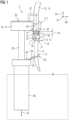
- Fig. 1 is a schematic representation of an intermediate step of a method for replacing a previously installed blade bearing 1 with a replacement blade bearing 2 in a wind turbine 3.
- the method will mainly be discussed using a global coordinate system spanned by a vertical direction 62 and a horizontal plane spanned by the up-wind direction 60 and the cross-wind direction 61.
- the wind turbine 3 is a floating off shore wind turbine 3 with a floating basis 60 attached to the seafloor by at least one anchor 61, which is only schematically shown.
- a toolkit comprising a service platform 8, connecting means 9 for connecting the service platform 8 to the wind turbine 3 and a replacement blade bearing 2 can be landed on a storage platform 35, e.g., by helicopter or by a ship crane.
- the storage platform 35 is located on top of the nacelle 11 of the wind turbine 3.
- the toolkit can also comprise various other tools and parts that will be discussed below, which are used in the process of replacing the previously installed blade bearing 1.
- a rotatable component 4 of the wind turbine 3 that is carrying the previously installed blade bearing 1, is then rotated into a service position 5, in which the previously installed blade bearing 1 is arranged at bottom of the rotatable component 4, as shown in fig. 1 .
- the rotatable component 4 is formed by the hub of the wind turbine 3.
- the rotor blade 6 is disconnected from the previously installed blade bearing 1 and lowered to create a free space 7 below the previously installed blade bearing 1.
- the rotor blade 6 is firstly lowered for a first part 23 of the lowering distance 24 by hydraulic actuators 27, as schematically shown in fig. 2 .
- These longer bolts 25 can be mounted to a respective actuator 27 that can, e.g., be supported by the previously installed blade bearing 1 itself and/or by the rotatable component 4.
- the actuators 27 are hydraulic actuators 27 in the example.
- the rotor blade 6 is supported by these actuators 27 and the remaining bolts (not shown) connecting the rotor blade 6 to the previously installed blade bearing 1 can therefore be removed.
- the actuators 27 can be actuated to lower the rotor blade 6 by shifting the bolts 25 that are attached to the rotor blade 6 in parallel to the rotational axis 26 of the previously installed blade bearing 1.
- At least two eyes 64 can be attached to the rotor blade 6, e.g., by screwing a bolt that is attached to the respective eye into an opening of the rotor blade, that can, e.g., be used during the normal operation of the wind turbine to house a bolt that is connecting the rotor blade 6 to the previously installed blade bearing 1.
- the rotor blade 6 is then lowered for a second part 28 of the lowering distance 24 by using the winch 29.
- the rotor blade 6 can be supported by a push rod 20 as shown in fig. 1 .
- the push rod 20 is mounted to a tower platform 34 mounted to the tower 33, especially as part of a transition piece.
- An end of the push rod 20, that is shaped as a fork 21 in the example, receives a supported section 22 of the lowered rotor blade 6.
- the spacing between the supported section 22 and the tower 33 can be adjusted by the actuator 63 of the push rod 20.
- the pair of the wires 15 used to support the lowered rotor blade 6 is pushed horizontally apart by a spreading component 16 that guides the wires 15 and that is formed in the example by a telescopic rod with an eye for the respective wire at each end.
- the free space 7 could be expanded by the use of an offset component 17 that is only schematically shown in fig. 1 , to shift the connection point 18, at which the respective wire 15 is connected, horizontally away from the lowered rotor blade 6 and/or the rotatable component 4 and/or the further rotor blade 14.
- the service platform 8 is then installed within the free space 7.
- the service platform is attached to the crane 32 while it is still arranged on the storage platform 35.
- the crane is then used to move the service platform 8 into the position shown in fig. 1 , in which it at least partially extends into the free space below the rotatable component 4 and the previously installed blade bearing 1.
- the connecting means 9 are used to mount of the service platform 8 to the rotatable component 4 in such a way, that the weight of the service platform 8 is at least partially supported by the rotatable component 4.
- the service platform 8 could, additionally or alternatively, be at least partially supported by a different supporting component 10 of the wind turbine 3, e.g., the nacelle 11.
- the connecting means 9 are formed by wires that are attached to the support platform 8 via a respective actuator 44, which is formed as a winch in the example, and attached to the rotatable component 4 via hard points on the outside of the rotatable component 4.
- the connecting means could, e.g., comprise telescopic rods and/or could be attached to the inside of the rotatable component 4, e.g., by passing through a manhole or a different opening.
- the crane 32 is disconnected from the service platform 8 after its installation and the connecting means 9 comprise only two wires to allow for an easy access to the service platform 8 by the crane 32.
- further connecting means 19 e.g., at least one additional wire and/or push rod, are therefore used to connect the service platform 8 to the lowered rotor blade 6.
- the previously installed blade bearing 1 is then unmounted from the rotatable component 4 and placed on a holding surface 43 of the service platform 8 as shown in fig. 3 .
- the distance 45 between the service platform 8 and the rotatable component 4 is decreased by the actuators 44 until the service platform 8 is located immediately below the previously installed blade bearing 1.
- the blade bearing 1 can then be disconnected from the rotatable part 4 and the service platform 4 can be lowered again, taking the previously installed blade bearing 1 with it.
- the previously installed blade bearing 1 can then be removed from the service of platform 8 via the crane 32 and put onto the storage platform 35 and the replacement blade bearing 2 can be lifted from the storage platform 35 onto the service platform 8.
- the service platform comprises a sliding part 37 that is movable with respect to a mounting part 36 of the service platform 8 along a movement path 38 that can be essentially parallel to the cross-wind direction 61.
- the crane 32 can in this case operate in an area of the holding surface 43 that extends beyond the area below the rotating component 4. An examplery embodiment of such a service platform will be discussed later with reference to fig.3 .
- the replacement blade bearing 2 can then be mounted to the rotatable component 4, e.g., by first moving the sliding part 37 of the support platform 8 in such a way, that the replacement blade bearing 2 is arranged below the previous mounting position 42 of the previously installed blade bearing 1.
- the service platform 8 can then be lifted by the actuators 44 to move the replacement blade bearing 2 into this mounting position 42. It can then be easily attached to the rotatable component, e.g., by bolts or similar means.
- the service platform 8 can be uninstalled and, e.g., be lifted onto to the service platform 35 by the crane 32.
- the rotor blade 6 can then be attached to the replacement blade bearing 2, e.g., by performing the previously discussed steps for unmounting and lowering the rotor blade 6 in reverse order.
- the wind turbine 3 is now in a refurbished state, in which the previously installed blade bearing 1 is replaced by the replacement blade bearing 2 and normal operation of the wind turbine 3 can resume.
- the service platform 8 and the previously installed blade bearing 1 can, e.g., later be removed by a helicopter, a ship crane, or by any other means from the storage platform 35.
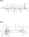
- FIG. 3 An example of a service platform 8 that comprises a sliding section 37, as discussed above, is shown in fig. 3 .
- the service platform 8 comprises the mounting part 36, which is connected to the rotatable component 4 after the service platform 8 is installed, and the sliding part 37 that is movable with respect to the mounting part 36 along the movement path 38, especially in the cross-wind direction 61.
- the replacement blade bearing 2 is already present on the holding surface 43 formed by the sliding part 37, before the previously installed blade bearing 1 is unmounted from the rotatable component 4 and placed on a free area of the holding surface 43. It is, e.g., possible that the service platform 8 is installed with the replacement blade bearing 2 already located on the holding surface 43 or that it is placed there before the unmounting of the previously installed blade bearing 1, e.g., by the crane 32.
- the sliding part 37 can be moved with respect to the mounting part 36 by an actuator 39. This can be used to shift the previously installed blade bearing 1 horizontally away from the previous mounting position 42 and/or to shift the replacement blade bearing 2 below this previous mounting position 42, as discussed above.
- the service platform 8 can also comprise a counterweight 40 that can be shifted by a further actuator 41.
- the step of unmounting the previously installed blade bearing 1 from the rotatable component 4 can therefore comprises the mounting a respective removal tool 46, shown in fig. 4 , to the previously installed blade bearing 1 by screwing a threaded part 48 of the respective removal tool 46 into a respective threaded through hole 49 of the outer ring 47 of the previously installed blade bearing 1.
- the threaded through hole 49 can especially be a respective one of the through holes 49 that are housing the bolts 50 used to attached the previously installed blade bearing 1 during the normal operation of the wind turbine 3.
- the threaded part 48 is tube shaped and houses a push rod 51 that is movable with respect to the threaded part 48 by an actuator 52 of the removal tool 46.
- the actuators 52 of the removal tools 46 are actuated to push the respective push rod 51 through the threaded part 48 and therefore through the threaded through hole 49 of the previously installed blade bearing 1 and against a counter surface 52 of the rotatable component 4, thereby pushing the threaded part 48 and thereby the previously installed blade bearing 1 away from the counter surface 52.
- Figure 5 shows a flow chart of a method for operating the wind turbine 3 and for feeding electrical and/or chemical energy 55, 56 to an electricity and/or chemical utility grid 58 and/or a chemical and/or electrical storage 59.
- step S1 the previously installed blade bearing 1 of a wind turbine 3 is replaced with a replacement blade bearing 2 to provide a refurbished state 53 of the wind turbine 3, as discussed above.
- step S2 the wind turbine 3 is used in its refurbished state 53 to generate electrical power 54 and/or electrical energy 55.
- the electrical energy 55 can, at least in part, be converted into chemical energy 56, e.g., by transforming the electrical energy 55 into hydrogen by electrolysis.
- step S3 the electrical power 54, the electrical energy 55, and/or the chemical energy 56 is at least partially transmitted to an energy receiving arrangement 57, which is preferably not positioned in international waters.
- the energy receiving arrangement 57 can, e.g., be positioned onshore, or within a 12-miles-zone of a respective sovereign national state over which the respective state has jurisdiction.
- step S4 at least a part of the electrical power 54, the electrical energy 55, and/or the chemical energy 57 is provided to an electrical and/or chemical utility grid 58, in particular to an onshore electrical and/or chemical utility grid 58, and/or a chemical and/or electrical storage 59.
Landscapes
- Engineering & Computer Science (AREA)
- Life Sciences & Earth Sciences (AREA)
- Sustainable Development (AREA)
- Sustainable Energy (AREA)
- Chemical & Material Sciences (AREA)
- Combustion & Propulsion (AREA)
- Mechanical Engineering (AREA)
- General Engineering & Computer Science (AREA)
- Wind Motors (AREA)
Priority Applications (2)
| Application Number | Priority Date | Filing Date | Title |
|---|---|---|---|
| EP23207930.1A EP4549729A1 (de) | 2023-11-06 | 2023-11-06 | Werkzeugsatz und verfahren zum ersetzen eines blattlagers und verfahren zum betrieb einer windturbine |
| PCT/EP2024/081156 WO2025098977A1 (en) | 2023-11-06 | 2024-11-05 | Toolkit and method for replacing a blade bearing and method for operating a wind turbine |
Applications Claiming Priority (1)
| Application Number | Priority Date | Filing Date | Title |
|---|---|---|---|
| EP23207930.1A EP4549729A1 (de) | 2023-11-06 | 2023-11-06 | Werkzeugsatz und verfahren zum ersetzen eines blattlagers und verfahren zum betrieb einer windturbine |
Publications (1)
| Publication Number | Publication Date |
|---|---|
| EP4549729A1 true EP4549729A1 (de) | 2025-05-07 |
Family
ID=88697463
Family Applications (1)
| Application Number | Title | Priority Date | Filing Date |
|---|---|---|---|
| EP23207930.1A Withdrawn EP4549729A1 (de) | 2023-11-06 | 2023-11-06 | Werkzeugsatz und verfahren zum ersetzen eines blattlagers und verfahren zum betrieb einer windturbine |
Country Status (2)
| Country | Link |
|---|---|
| EP (1) | EP4549729A1 (de) |
| WO (1) | WO2025098977A1 (de) |
Citations (4)
| Publication number | Priority date | Publication date | Assignee | Title |
|---|---|---|---|---|
| US20130340256A1 (en) * | 2012-06-21 | 2013-12-26 | Hitachi, Ltd. | Bearing replacement method and tools for rotating machine |
| US20160327017A1 (en) * | 2015-05-07 | 2016-11-10 | General Electric Company | System and method for replacing a pitch bearing |
| US20190040848A1 (en) * | 2017-08-03 | 2019-02-07 | Barnhart Crane and Rigging Co. | Wind Turbine Bearing Removal and Installation Device and Method |
| EP3263888B1 (de) * | 2016-06-30 | 2023-10-04 | Siemens Gamesa Renewable Energy A/S | Verfahren zur handhabung einer windturbinenrotorblattanstelllagereinheit |
-
2023
- 2023-11-06 EP EP23207930.1A patent/EP4549729A1/de not_active Withdrawn
-
2024
- 2024-11-05 WO PCT/EP2024/081156 patent/WO2025098977A1/en active Pending
Patent Citations (4)
| Publication number | Priority date | Publication date | Assignee | Title |
|---|---|---|---|---|
| US20130340256A1 (en) * | 2012-06-21 | 2013-12-26 | Hitachi, Ltd. | Bearing replacement method and tools for rotating machine |
| US20160327017A1 (en) * | 2015-05-07 | 2016-11-10 | General Electric Company | System and method for replacing a pitch bearing |
| EP3263888B1 (de) * | 2016-06-30 | 2023-10-04 | Siemens Gamesa Renewable Energy A/S | Verfahren zur handhabung einer windturbinenrotorblattanstelllagereinheit |
| US20190040848A1 (en) * | 2017-08-03 | 2019-02-07 | Barnhart Crane and Rigging Co. | Wind Turbine Bearing Removal and Installation Device and Method |
Also Published As
| Publication number | Publication date |
|---|---|
| WO2025098977A1 (en) | 2025-05-15 |
Similar Documents
| Publication | Publication Date | Title |
|---|---|---|
| EP2982862B1 (de) | Verfahren und vorrichtung zum austauschen von schaufeln bei windturbinen | |
| EP2585712B1 (de) | Hebevorrichtung und verfahren zum positionieren eines sperrigen objects | |
| US9057360B2 (en) | Wind power generator and yaw bearing replacement method for a wind power generator | |
| EP2868914B1 (de) | Vorrichtung und Verfahren zum Anbringen und Entfernen einer Schaufel einer Windturbine | |
| WO2013051167A1 (en) | Blade attaching and detaching device and method for wind turbine generator | |
| EP2908000B1 (de) | Hebevorrichtung zur montage und entfernung von komponenten einer windturbine | |
| US20130051924A1 (en) | Offshore structures and associated apparatus and methods | |
| KR20150135246A (ko) | 풍력 터빈의 회전자 블레이드를 배치하기 위한 장치 및 방법 | |
| US20120027523A1 (en) | Device and method for assembling a structure at sea | |
| EP3070044B1 (de) | Hebesysteme und -verfahren | |
| EP2890626A1 (de) | Vorrichtung und verfahren zur montage einer struktur | |
| EP3708831A1 (de) | Vorrichtung zum anheben einer windturbinenwelle und verfahren zum anheben der windturbinenwelle | |
| CN102701083A (zh) | 风力发电机部件更换专用设备及方法 | |
| EP2256079B1 (de) | Vorrichtung und Verfahren zur Montage einer Struktur auf See | |
| EP4549729A1 (de) | Werkzeugsatz und verfahren zum ersetzen eines blattlagers und verfahren zum betrieb einer windturbine | |
| EP2495433B1 (de) | Windturbine und Verfahren zum Anheben eines Getriebedrehmomentarms | |
| US20240344504A1 (en) | Methods for handling a load, in particular for installing or removing a blade on an offshore wind turbine, and devices for carrying out such methods | |
| EP4251875B1 (de) | Vorrichtung und verfahren zur montage einer windturbinenkomponente an einem windturbinenturm | |
| CN109113938B (zh) | 风电机组用的分段式变桨轴承加强法兰及其空中安装方法 | |
| JP2023552909A (ja) | 浮遊式洋上風力発電所の組立方法 | |
| EP4542027A1 (de) | Errichten einer offshore-windturbine | |
| EP3875753B1 (de) | Verfahren zur montage einer windturbine | |
| WO2025247939A1 (en) | A method for optimizing hoisting performance of a wind turbine hoisting system. | |
| GB2628742A (en) | Methods for replacing and installing wind turbine blades | |
| WO2019120411A1 (en) | Method and system for lifting a wind turbine component |
Legal Events
| Date | Code | Title | Description |
|---|---|---|---|
| PUAI | Public reference made under article 153(3) epc to a published international application that has entered the european phase |
Free format text: ORIGINAL CODE: 0009012 |
|
| STAA | Information on the status of an ep patent application or granted ep patent |
Free format text: STATUS: THE APPLICATION HAS BEEN PUBLISHED |
|
| AK | Designated contracting states |
Kind code of ref document: A1 Designated state(s): AL AT BE BG CH CY CZ DE DK EE ES FI FR GB GR HR HU IE IS IT LI LT LU LV MC ME MK MT NL NO PL PT RO RS SE SI SK SM TR |
|
| STAA | Information on the status of an ep patent application or granted ep patent |
Free format text: STATUS: THE APPLICATION IS DEEMED TO BE WITHDRAWN |
|
| 18D | Application deemed to be withdrawn |
Effective date: 20251108 |