EP4549731A1 - Windenergieerzeugungsvorrichtung - Google Patents
Windenergieerzeugungsvorrichtung Download PDFInfo
- Publication number
- EP4549731A1 EP4549731A1 EP23852321.1A EP23852321A EP4549731A1 EP 4549731 A1 EP4549731 A1 EP 4549731A1 EP 23852321 A EP23852321 A EP 23852321A EP 4549731 A1 EP4549731 A1 EP 4549731A1
- Authority
- EP
- European Patent Office
- Prior art keywords
- gear
- transmission mechanism
- rotation transmission
- hub
- power generation
- Prior art date
- Legal status (The legal status is an assumption and is not a legal conclusion. Google has not performed a legal analysis and makes no representation as to the accuracy of the status listed.)
- Pending
Links
Images






Classifications
-
- H—ELECTRICITY
- H02—GENERATION; CONVERSION OR DISTRIBUTION OF ELECTRIC POWER
- H02K—DYNAMO-ELECTRIC MACHINES
- H02K7/00—Arrangements for handling mechanical energy structurally associated with dynamo-electric machines, e.g. structural association with mechanical driving motors or auxiliary dynamo-electric machines
- H02K7/10—Structural association with clutches, brakes, gears, pulleys or mechanical starters
- H02K7/116—Structural association with clutches, brakes, gears, pulleys or mechanical starters with gears
-
- F—MECHANICAL ENGINEERING; LIGHTING; HEATING; WEAPONS; BLASTING
- F03—MACHINES OR ENGINES FOR LIQUIDS; WIND, SPRING, OR WEIGHT MOTORS; PRODUCING MECHANICAL POWER OR A REACTIVE PROPULSIVE THRUST, NOT OTHERWISE PROVIDED FOR
- F03D—WIND MOTORS
- F03D1/00—Wind motors with rotation axis substantially parallel to the air flow entering the rotor
- F03D1/06—Rotors
- F03D1/065—Rotors characterised by their construction elements
- F03D1/0691—Rotors characterised by their construction elements of the hub
-
- F—MECHANICAL ENGINEERING; LIGHTING; HEATING; WEAPONS; BLASTING
- F03—MACHINES OR ENGINES FOR LIQUIDS; WIND, SPRING, OR WEIGHT MOTORS; PRODUCING MECHANICAL POWER OR A REACTIVE PROPULSIVE THRUST, NOT OTHERWISE PROVIDED FOR
- F03D—WIND MOTORS
- F03D1/00—Wind motors with rotation axis substantially parallel to the air flow entering the rotor
- F03D1/101—Nacelles
-
- F—MECHANICAL ENGINEERING; LIGHTING; HEATING; WEAPONS; BLASTING
- F03—MACHINES OR ENGINES FOR LIQUIDS; WIND, SPRING, OR WEIGHT MOTORS; PRODUCING MECHANICAL POWER OR A REACTIVE PROPULSIVE THRUST, NOT OTHERWISE PROVIDED FOR
- F03D—WIND MOTORS
- F03D15/00—Transmission of mechanical power
- F03D15/10—Transmission of mechanical power using gearing not limited to rotary motion, e.g. with oscillating or reciprocating members
- F03D15/101—Transmission of mechanical power using gearing not limited to rotary motion, e.g. with oscillating or reciprocating members of the epicyclic or planetary type
-
- F—MECHANICAL ENGINEERING; LIGHTING; HEATING; WEAPONS; BLASTING
- F03—MACHINES OR ENGINES FOR LIQUIDS; WIND, SPRING, OR WEIGHT MOTORS; PRODUCING MECHANICAL POWER OR A REACTIVE PROPULSIVE THRUST, NOT OTHERWISE PROVIDED FOR
- F03D—WIND MOTORS
- F03D15/00—Transmission of mechanical power
- F03D15/207—Transmission of mechanical power to multiple generators, e.g. in series
-
- F—MECHANICAL ENGINEERING; LIGHTING; HEATING; WEAPONS; BLASTING
- F03—MACHINES OR ENGINES FOR LIQUIDS; WIND, SPRING, OR WEIGHT MOTORS; PRODUCING MECHANICAL POWER OR A REACTIVE PROPULSIVE THRUST, NOT OTHERWISE PROVIDED FOR
- F03D—WIND MOTORS
- F03D80/00—Details, components or accessories not provided for in groups F03D1/00 - F03D17/00
- F03D80/80—Arrangement of components within nacelles or towers
- F03D80/82—Arrangement of components within nacelles or towers of electrical components
- F03D80/821—Arrangement of components within nacelles or towers of electrical components within nacelles
-
- F—MECHANICAL ENGINEERING; LIGHTING; HEATING; WEAPONS; BLASTING
- F03—MACHINES OR ENGINES FOR LIQUIDS; WIND, SPRING, OR WEIGHT MOTORS; PRODUCING MECHANICAL POWER OR A REACTIVE PROPULSIVE THRUST, NOT OTHERWISE PROVIDED FOR
- F03D—WIND MOTORS
- F03D80/00—Details, components or accessories not provided for in groups F03D1/00 - F03D17/00
- F03D80/80—Arrangement of components within nacelles or towers
- F03D80/88—Arrangement of components within nacelles or towers of mechanical components
- F03D80/881—Arrangement of components within nacelles or towers of mechanical components within nacelles
-
- F—MECHANICAL ENGINEERING; LIGHTING; HEATING; WEAPONS; BLASTING
- F03—MACHINES OR ENGINES FOR LIQUIDS; WIND, SPRING, OR WEIGHT MOTORS; PRODUCING MECHANICAL POWER OR A REACTIVE PROPULSIVE THRUST, NOT OTHERWISE PROVIDED FOR
- F03D—WIND MOTORS
- F03D9/00—Adaptations of wind motors for special use; Combinations of wind motors with apparatus driven thereby; Wind motors specially adapted for installation in particular locations
- F03D9/20—Wind motors characterised by the driven apparatus
- F03D9/25—Wind motors characterised by the driven apparatus the apparatus being an electrical generator
-
- F—MECHANICAL ENGINEERING; LIGHTING; HEATING; WEAPONS; BLASTING
- F16—ENGINEERING ELEMENTS AND UNITS; GENERAL MEASURES FOR PRODUCING AND MAINTAINING EFFECTIVE FUNCTIONING OF MACHINES OR INSTALLATIONS; THERMAL INSULATION IN GENERAL
- F16H—GEARING
- F16H1/00—Toothed gearings for conveying rotary motion
- F16H1/28—Toothed gearings for conveying rotary motion with gears having orbital motion
-
- F—MECHANICAL ENGINEERING; LIGHTING; HEATING; WEAPONS; BLASTING
- F16—ENGINEERING ELEMENTS AND UNITS; GENERAL MEASURES FOR PRODUCING AND MAINTAINING EFFECTIVE FUNCTIONING OF MACHINES OR INSTALLATIONS; THERMAL INSULATION IN GENERAL
- F16H—GEARING
- F16H37/00—Combinations of mechanical gearings, not provided for in groups F16H1/00 - F16H35/00
- F16H37/02—Combinations of mechanical gearings, not provided for in groups F16H1/00 - F16H35/00 comprising essentially only toothed or friction gearings
- F16H37/06—Combinations of mechanical gearings, not provided for in groups F16H1/00 - F16H35/00 comprising essentially only toothed or friction gearings with a plurality of driving or driven shafts; with arrangements for dividing torque between two or more intermediate shafts
- F16H37/065—Combinations of mechanical gearings, not provided for in groups F16H1/00 - F16H35/00 comprising essentially only toothed or friction gearings with a plurality of driving or driven shafts; with arrangements for dividing torque between two or more intermediate shafts with a plurality of driving or driven shafts
-
- H—ELECTRICITY
- H02—GENERATION; CONVERSION OR DISTRIBUTION OF ELECTRIC POWER
- H02K—DYNAMO-ELECTRIC MACHINES
- H02K7/00—Arrangements for handling mechanical energy structurally associated with dynamo-electric machines, e.g. structural association with mechanical driving motors or auxiliary dynamo-electric machines
- H02K7/18—Structural association of electric generators with mechanical driving motors, e.g. with turbines
- H02K7/1807—Rotary generators
- H02K7/1823—Rotary generators structurally associated with turbines or similar engines
- H02K7/183—Rotary generators structurally associated with turbines or similar engines wherein the turbine is a wind turbine
- H02K7/1838—Generators mounted in a nacelle or similar structure of a horizontal axis wind turbine
-
- F—MECHANICAL ENGINEERING; LIGHTING; HEATING; WEAPONS; BLASTING
- F05—INDEXING SCHEMES RELATING TO ENGINES OR PUMPS IN VARIOUS SUBCLASSES OF CLASSES F01-F04
- F05B—INDEXING SCHEME RELATING TO WIND, SPRING, WEIGHT, INERTIA OR LIKE MOTORS, TO MACHINES OR ENGINES FOR LIQUIDS COVERED BY SUBCLASSES F03B, F03D AND F03G
- F05B2220/00—Application
- F05B2220/70—Application in combination with
- F05B2220/706—Application in combination with an electrical generator
-
- F—MECHANICAL ENGINEERING; LIGHTING; HEATING; WEAPONS; BLASTING
- F05—INDEXING SCHEMES RELATING TO ENGINES OR PUMPS IN VARIOUS SUBCLASSES OF CLASSES F01-F04
- F05B—INDEXING SCHEME RELATING TO WIND, SPRING, WEIGHT, INERTIA OR LIKE MOTORS, TO MACHINES OR ENGINES FOR LIQUIDS COVERED BY SUBCLASSES F03B, F03D AND F03G
- F05B2240/00—Components
- F05B2240/10—Stators
- F05B2240/14—Casings, housings, nacelles, gondels or the like, protecting or supporting assemblies there within
-
- F—MECHANICAL ENGINEERING; LIGHTING; HEATING; WEAPONS; BLASTING
- F05—INDEXING SCHEMES RELATING TO ENGINES OR PUMPS IN VARIOUS SUBCLASSES OF CLASSES F01-F04
- F05B—INDEXING SCHEME RELATING TO WIND, SPRING, WEIGHT, INERTIA OR LIKE MOTORS, TO MACHINES OR ENGINES FOR LIQUIDS COVERED BY SUBCLASSES F03B, F03D AND F03G
- F05B2240/00—Components
- F05B2240/40—Use of a multiplicity of similar components
-
- F—MECHANICAL ENGINEERING; LIGHTING; HEATING; WEAPONS; BLASTING
- F05—INDEXING SCHEMES RELATING TO ENGINES OR PUMPS IN VARIOUS SUBCLASSES OF CLASSES F01-F04
- F05B—INDEXING SCHEME RELATING TO WIND, SPRING, WEIGHT, INERTIA OR LIKE MOTORS, TO MACHINES OR ENGINES FOR LIQUIDS COVERED BY SUBCLASSES F03B, F03D AND F03G
- F05B2240/00—Components
- F05B2240/60—Shafts
- F05B2240/61—Shafts hollow
-
- F—MECHANICAL ENGINEERING; LIGHTING; HEATING; WEAPONS; BLASTING
- F05—INDEXING SCHEMES RELATING TO ENGINES OR PUMPS IN VARIOUS SUBCLASSES OF CLASSES F01-F04
- F05B—INDEXING SCHEME RELATING TO WIND, SPRING, WEIGHT, INERTIA OR LIKE MOTORS, TO MACHINES OR ENGINES FOR LIQUIDS COVERED BY SUBCLASSES F03B, F03D AND F03G
- F05B2260/00—Function
- F05B2260/40—Transmission of power
- F05B2260/403—Transmission of power through the shape of the drive components
- F05B2260/4031—Transmission of power through the shape of the drive components as in toothed gearing
- F05B2260/40311—Transmission of power through the shape of the drive components as in toothed gearing of the epicyclic, planetary or differential type
-
- F—MECHANICAL ENGINEERING; LIGHTING; HEATING; WEAPONS; BLASTING
- F16—ENGINEERING ELEMENTS AND UNITS; GENERAL MEASURES FOR PRODUCING AND MAINTAINING EFFECTIVE FUNCTIONING OF MACHINES OR INSTALLATIONS; THERMAL INSULATION IN GENERAL
- F16H—GEARING
- F16H1/00—Toothed gearings for conveying rotary motion
- F16H1/02—Toothed gearings for conveying rotary motion without gears having orbital motion
- F16H1/20—Toothed gearings for conveying rotary motion without gears having orbital motion involving more than two intermeshing members
- F16H1/22—Toothed gearings for conveying rotary motion without gears having orbital motion involving more than two intermeshing members with a plurality of driving or driven shafts; with arrangements for dividing torque between two or more intermediate shafts
- F16H1/227—Toothed gearings for conveying rotary motion without gears having orbital motion involving more than two intermeshing members with a plurality of driving or driven shafts; with arrangements for dividing torque between two or more intermediate shafts comprising two or more gearwheels in mesh with the same internally toothed wheel
-
- F—MECHANICAL ENGINEERING; LIGHTING; HEATING; WEAPONS; BLASTING
- F16—ENGINEERING ELEMENTS AND UNITS; GENERAL MEASURES FOR PRODUCING AND MAINTAINING EFFECTIVE FUNCTIONING OF MACHINES OR INSTALLATIONS; THERMAL INSULATION IN GENERAL
- F16H—GEARING
- F16H1/00—Toothed gearings for conveying rotary motion
- F16H1/28—Toothed gearings for conveying rotary motion with gears having orbital motion
- F16H1/46—Systems consisting of a plurality of gear trains each with orbital gears, i.e. systems having three or more central gears
-
- F—MECHANICAL ENGINEERING; LIGHTING; HEATING; WEAPONS; BLASTING
- F16—ENGINEERING ELEMENTS AND UNITS; GENERAL MEASURES FOR PRODUCING AND MAINTAINING EFFECTIVE FUNCTIONING OF MACHINES OR INSTALLATIONS; THERMAL INSULATION IN GENERAL
- F16H—GEARING
- F16H57/00—General details of gearing
- F16H57/08—General details of gearing of gearings with members having orbital motion
- F16H2057/085—Bearings for orbital gears
-
- Y—GENERAL TAGGING OF NEW TECHNOLOGICAL DEVELOPMENTS; GENERAL TAGGING OF CROSS-SECTIONAL TECHNOLOGIES SPANNING OVER SEVERAL SECTIONS OF THE IPC; TECHNICAL SUBJECTS COVERED BY FORMER USPC CROSS-REFERENCE ART COLLECTIONS [XRACs] AND DIGESTS
- Y02—TECHNOLOGIES OR APPLICATIONS FOR MITIGATION OR ADAPTATION AGAINST CLIMATE CHANGE
- Y02E—REDUCTION OF GREENHOUSE GAS [GHG] EMISSIONS, RELATED TO ENERGY GENERATION, TRANSMISSION OR DISTRIBUTION
- Y02E10/00—Energy generation through renewable energy sources
- Y02E10/70—Wind energy
- Y02E10/72—Wind turbines with rotation axis in wind direction
Definitions
- the present invention relates to a wind power generation device, and more particularly to the configuration of a horizontal type wind power generation device.
- Wind power generation devices In a wind power generation device, blades are fixed to a hub, and when the blades catch wind, the hub rotates, and the rotation of the hub is transmitted to a generator to generate electricity.
- Wind power generation devices can be divided into horizontal types, in which the rotation shaft of the hub is arranged horizontally, and vertical types, in which the rotation shaft of the hub is arranged vertically.
- types shown in schematic diagrams of Figs. 10 and 11 are known as the horizontal type wind power generation device.
- a main shaft 104 is coupled to a hub 102 and rotatably supported by a bearing called a main shaft bearing 106, and the rotation of the hub 102 is transmitted to a speed increaser 108.
- the speed increaser 108 normally uses a planetary gear speed increase mechanism 110 in the first stage, and utilizes carrier input and solar output in order to obtain a large speed increase ratio.
- a two-stage parallel shaft gear speed increaser 112 is provided, and the total speed increase ratio is increased to about 100, and electricity is generated by a generator 114 (see, e.g., PATENT LITERATURE 1).
- FIG. 11 Another type of wind power generation device 200 shown in Fig. 11 is a so-called direct type in which the rotation of the hub 202 is directly transmitted to the generator 206 without speed increase.
- a bearing 204 is disposed inside the hub 202, and the outer ring side of the bearing 204 is transmitted to an outer rotor type generator 206 without speed increase.
- a magnet is attached to the rotor 208 of the generator 206.
- it has a simple structure, it uses a large amount of magnets, is an extremely expensive system, and is not suitable for large power generation (see, e.g., PATENT LITERATURE 2).
- wind energy mainly flows parallel to the ground or water surface, so horizontal wind turbines, which have the blades rotated horizontally to the wind, are the mainstream.
- horizontal type wind power generation devices have become larger.
- PATENT LITERATUREs 2 and 3 disclose a configuration in which a large gear is fixed to a main shaft coupled to a hub, a plurality of small gears are provided to engage with the large gear, and the rotation of each of the small gears is transmitted to a generator.
- an increase in the size of a horizontal type wind power generation device leads to an increase in torque and weight, which increases the probability of failure, reduces the operating rate, and increases repair costs, resulting in higher costs.
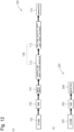
- Fig. 10 is a block diagram of two conventional types of wind power generation devices 100, 200. As shown in Fig. 12 , the two conventional types transmit the wind energy obtained by the blades 101, 201 to the generators 114, 208 through a single path without branching, and therefore are not suitable for enlarging the wind power generation devices 100, 200.
- the torque increases in proportion to the 1.5-th power of the output, and the weight of the main parts that transmit the torque, such as the main shaft, the speed increaser, and the generator, also increases in proportion to the 1.5-th power of the output (hereinafter, this law will be referred to as the "1.5-th power law").
- the increase in torque also increases the failure of mechanical parts such as bearings, and durability and maintenance costs become problems. Therefore, there are restrictions on increasing the output, and it is not easy to achieve it.
- the hub rotation speed is a constant speed at the tip of the blade, and 320 km/h is often used as this value.
- the hub rotation speed is 320/3.6/ ( ⁇ ⁇ d), which is 0.526 rps (31.56 rpm).
- Calculating the torque from the rotations, 1 MW is 302.59 kNm.
- the blade diameter required is 45,454.55 m 2 , so the blade diameter d is 240.57 m, and the rotation speed is 0.11763 rps (7.056 rpm).
- the torque is 2,706.3 kNm, which is 89.44 times that of 1 MW. In other words, an increase in output leads to an increase in torque.
- the rotation speed decreases in proportion to the -0.5-th power of the output, and the torque increases in proportion to the 1.5-th power of the output.
- weight 2.4 ⁇ P 1.5 .
- weight is proportional to the 1.5-th power of output means that when torque is transmitted through a single path, such as not only the main shaft but also a speed increaser or generator, the weight of the part through which torque is transmitted cannot escape this law.
- the planetary gear speed increase mechanism 110 of the wind power generation device 100 shown in Fig. 10 increases the speed with the solar output by the carrier input.
- the planetary carrier is usually installed with a roller bearing that supports the shaft of the planetary gear. This roller bearing is subject to an unbalanced load caused by both the revolution of the planetary gear around the sun axis and the rotation of the planetary gear, and is prone to a burn-in phenomenon called smearing.
- failures of the planetary gear mechanism are concentrated around the carrier axis, so the enlargement of the wind power generation device 100 promotes failures of the planetary gear speed increase mechanism 110.
- the bearing 106 of the main shaft 104 of the wind power generation device 100 is similarly susceptible to smearing since it is subjected to not only the weight of the main shaft 104 but also fluctuating loads due to wind and stress in a cantilever state.
- the rotation speed and torque can be calculated using the equations 1 and 2 already explained.
- the generator 206 of the direct type wind power generation device 200 must handle a torque that increases by the 1.5-th power of the output.
- the torque is proportional to the square of the rotor diameter of the generator 206 and is proportional to the length of the rotor.
- the amount of power generated by the generator 206 is proportional to the volume.
- the volume of the rotor increases in proportion to the 1.5-th power of P (output). Since weight is proportional to volume, the weight of the generator 206 also increases in proportion to the 1.5-th power in the direct type.
- an increase in output will result in an increase in the weight of the nacelle greater than the increase in output, because torque is proportional to the 1.5-th power of the output, and there is a risk of a cost increase greater than the increase in output.
- an object of the present invention is to provide a wind power generation device that can be increased in size while suppressing increases in costs.
- the present invention provides a wind power generation device configured as follows.
- the wind power generation device is equipped with:
- the rotation transmission mechanism includes:
- the large gear of the rotation transmission mechanism has internal teeth or external teeth.
- the small gear of the rotation transmission mechanism has external teeth that engages with the internal teeth or the external teeth of the large gear of the rotation transmission mechanism.
- the large gear of the rotation transmission mechanism has a through hole that communicates with the hollow hole of the hub, and the fixed portion of the nacelle is coupled to a machine base of the nacelle via the through hole.
- the torque is distributed to multiple systems by the large gear and multiple small gears of the rotation transmission mechanism, and electricity is generated by multiple generators.
- This makes it possible to reduce the weight of the entire system distributed by the rotation transmission mechanism compared to when torque is not distributed and electricity is generated by only one generator.
- the large gear that integrally rotates with the hub does not need to be large if the number of small gears that engage with the large gear is increased. Therefore, with the above configuration, the weight of the mechanism inside the nacelle of the wind power generation device can be reduced compared to conventional wind power generation devices.
- the torque acting on the bearings of each system of the rotation transmission mechanism is also reduced, making the bearings less likely to fail. Because the outer ring of a bearing mounted on the inside of the hub rotates with the hub, it is easier to supply lubricating oil and less likely to fail than when a bearing is mounted on the outside of the hub, i.e., when the outer ring of the bearing is stationary.
- the size can be increased while suppressing increases in costs.
- the wind power generation device includes: (g) a converter installed for each generator, functioning as an AC-DC converter to convert the alternating current generated by the generator into direct current; and (h) a common battery to which the direct current is supplied from each of the converters.
- the battery is charged by direct current supplied from the converter and can accumulate energy generated by multiple generators.
- the wind power generation device further includes a control device that controls the converter so as to drive the generator by the converter and generate power as regenerative energy by the generator.
- the rotational fluctuation of the hub can be suppressed, and smearing of the bearing can be suppressed.
- the wind power generation device further includes (k) a housing that accommodates the rotation transmission mechanism and the generator.
- the nacelle further includes a first longitudinal member and a second longitudinal member fixed to the machine base.
- the fixed portion is coupled to the machine base via the first longitudinal member.
- the housing is fixed to the first longitudinal member and the second longitudinal member so as to transmit at least a portion of a load acting on the nacelle from the hub.
- the housing can be used as a strength member of the nacelle.
- the rotation transmission mechanism uses a planetary gear mechanism (d-iii) constituted by a screw-like gear for the bearing of a rotating body whose speed is increased in the rotation transmission mechanism.
- a planetary gear mechanism (d-iii) constituted by a screw-like gear for the bearing of a rotating body whose speed is increased in the rotation transmission mechanism.
- the engaging ratio can be ensured and rotation can be transmitted without slippage, making it possible to suppress smearing of the bearing.
- a planetary gear mechanism constituted of screw-like gears has a small number of teeth and a large module, which is reference pitch circle/number of teeth, and therefore is strong. Furthermore, even if the overlapping engaging ratio of screw-like gears is increased, engaging occurs only in the vicinity of the reference pitch circle diameter, and the frontal engaging ratio is reduced, a sufficient engaging ratio can be ensured and slippage on the tooth surface can be extremely reduced. Furthermore, thrust forces can be cancelled by making the tooth twisted in opposite directions. Thus, extremely strong and efficient engaging can be achieved. In this way, a planetary gear mechanism constituted of screw-like gears can ensure the engaging ratio and transmit rotation without slippage, so that when used in a bearing, smearing of the bearing can be suppressed.
- the small gear of the rotation transmission mechanism, the rotation transmission mechanism, the generator, and the converter are all or partially coupled to each other to form an assembly.
- the rotation transmission mechanism includes a first planetary gear mechanism and a second planetary gear mechanism constituted by (d-iv) screw-like gears.
- the sun gears of the first planetary gear mechanism and the second planetary gear mechanism are coupled to each other and rotate together.
- the planetary gears of the first planetary gear mechanism and the second planetary gear mechanism are coupled to each other and rotate together.
- the rotation of the small gear of the rotation transmission mechanism is transmitted to an internal gear of the first planetary gear mechanism.
- the internal gear of the second planetary gear mechanism is fixed to the nacelle.
- the rotation of the sun gear of the second planetary gear mechanism is transmitted to the generator.
- the wind power generation device is configured so that personnel can enter the nacelle from the bottom of the nacelle and pass through the hollow hole in the hub to reach a position in the hub opposite the blade.
- the large gear of the rotation transmission mechanism has the internal teeth rather than the external teeth.
- the radial dimension can be made smaller than when the large gear of the rotation transmission mechanism has external teeth and multiple small gears that engage with the external teeth of the large gear are arranged outside the large gear. Also, since the lubricating oil accumulates at the bottom of the internal teeth of the large gear of the rotation transmission mechanism, the lubricating oil can be easily and reliably supplied to the tooth surfaces of the large gear and small gear that engage with each other, compared to when the speed is increased by distributing by the large gear that has external teeth, and the small gear.
- the large gear of the rotation transmission mechanism has the internal teeth rather than the external teeth.
- the internal teeth of the large gear of the rotation transmission mechanism include first and second screw-like internal teeth that are internal teeth of screw-like gears twisting in opposite directions to each other.
- the external teeth of the small gear of the rotation transmission mechanism include first and second screw-like external teeth that are external teeth of screw-like gears twisting in opposite directions to each other. The first screw-like internal teeth and the first screw-like external teeth engage with each other, and the second screw-like internal teeth and the second screw-like external teeth engage with each other.
- the thrust force acting on the rotation transmission mechanism can be suppressed. Also, it is easy to configure the rotation transmission mechanism so that no excessive force acts on the engaging of the large gear and small gear.
- a planetary gear mechanism constituted of a screw-like gear is used for the bearing of the rotation shaft of the small gear of the rotation transmission mechanism.
- the engaging ratio can be ensured and rotation can be transmitted without causing slippage, thereby suppressing smearing of the bearing.
- Fig. 1 is a schematic diagram of the wind power generation device 10.
- a wind power generation device 10 includes a hub 12, blades 11 fixed to the hub 12, a nacelle 14 that rotatably supports the hub 12 via bearings 13, and a tower 17 that supports a machine base 14x of the nacelle 14.
- the wind power generation device 10 further includes a floating body 18 to which the base end of the tower 17 is fixed in offshore wind power generation, while the base end of the tower 17 is fixed to the land in onshore wind power generation.
- the tower 17 supports the nacelle 14 in the air.
- a hollow hole 12x is formed in the hub 12, and a bearing 13 is disposed in the hollow hole 12x.
- the bearing 13 includes an outer ring 13b and an inner ring 13a that are rotatable relative to one another, and the outer ring 13b is fixed to the hub 12, and the inner ring 13a is fixed to a fixed portion 14a.
- the fixed portion 14a is fixed to a machine base 14x of the nacelle 14.
- a rotation transmission mechanism 15 that distributes the rotation of the hub 12 to multiple systems 15p, 15q and increases the speed is installed in the nacelle 14. Although two systems 15p, 15q are illustrated in Fig. 1 , three or more systems may be provided.
- the rotation transmission mechanism 15 includes a ring gear 15a that integrally rotates with the hub 12, and a plurality of external gears 15b that engage with the ring gear 15a.
- Each of the plurality of systems 15p, 15q of the rotation transmission mechanism 15 includes one external gear 15b, and preferably includes a speed increase mechanism 15c.
- the ring gear 15a has a through hole 15r that communicates with the hollow hole 12x of the hub 12, and as will be described later, a fixed portion 14a of the nacelle 14 is coupled to a machine base 14x of the nacelle 14 via the through hole 15r.
- the rotation transmission mechanism 15 may be configured such that, instead of the ring gear 15a, an external gear that integrally rotates with the hub 12 is provided, and multiple external gears 15b engage with this external gear.
- a through hole that communicates with the hollow hole 12x of the hub 12 is formed in the external gear provided in place of the ring gear 15a, and the fixed portion 14a of the nacelle 14 is coupled to the machine base 14x of the nacelle 14 via this through hole.
- a generator 16 is provided in the nacelle 14 for each of the systems 15 p and 15 q of the rotation transmission mechanism 15 .
- the converter 16a is PWM controlled by a drive pulse generator 16p, and adjusts the load of the generator 16 to control the rotation and load of the blades 11. Since there are multiple sets of generators 16 and converters 16a, a power generation command device 16q sends a control signal to the drive pulse generator 16p to command the load of each generator 16 and control the amount of power generation.
- the drive pulse generator 16p and the power generation command device 16q are a control device that controls the converter 16a, and perform control so that the generator 16 is driven by the converter 16a and the generator 16 generates power as regenerative energy.
- the generators 16 can be skewed to reduce the detent torque and facilitate rotation from a standstill. Furthermore, if only one of the multiple generators 16 is controlled to generate power, the load is small and power can be generated from a light breeze. In other words, by changing the number of generators 16 that act as a load, i.e., the number of generators 16 that generate power, a wide range of wind power can be handled.
- the converter 16a generates power as regenerative energy by switching the IGBTs and the like to flow the alternating current generated by the generator 16 to the battery 19 at appropriate timing.
- the converter 16a also functions as an inverter in the same circuit, so that the generator 16 can be driven like a motor to rotate the blades 11 by applying the voltage of the battery 19 to the generator 16 at appropriate timing.
- the power generation command device 16q drives the blades 11 using the converter 16a, adjusts the rotation speed to an appropriate number according to the wind volume, and then commands the converter 16a to perform regeneration, thereby generating electricity as regenerative energy.
- the DC-AC converter 19a can connect the batteries 19 in parallel if the wind turbines have the same battery specifications, so the energy of multiple wind power generation devices 10 can be converted to alternating current by a single DC-AC converter 19a and transmitted.
- the battery 19 Since the battery 19 is required to have improved maintainability, it is most reasonable to install it on the floating body 18, which is easily accessible. In the case of onshore power generation, the battery 19 is placed under the tower 17 or on land.
- a separate battery may be disposed for each generator 16 within the nacelle 14.
- the converter 16a and the battery may be incorporated together with the generator 16 into an assembly 40 or 42, which will be described later.
- the IGBTs of the converter are often configured with the same N-type for H and L.
- the H side must be driven with a voltage obtained by adding the voltage for driving the IGBTs to the voltage connected to the coil of the generator 16.
- a snubber capacitor 16t is inserted between the power supply ground of the IGBT to remove so-called high-frequency ringing noise.
- the external gear 15b that engages with the ring gear 15a is rotatably fixed at both ends via bearings to a portion that is integrated with the bottom of the nacelle 14 (machine base 14x), for example by an assembly 44 described later.
- the components integrated with the bottom of the nacelle are the inner ring 13a of the bearing 13, the bearing 15f of the external gear 15b, the speed increase mechanism 15c at the rear end thereof, the generator 16, the converter 16a, etc. Since there are multiple sets of the speed increase mechanism 15c, the generator 16, and the converter 16a due to distribution, integrating them, i.e., modularizing them, like assemblies 40 and 42 described below, allows the same items to be manufactured, costs to be reduced, and they are easy to handle.
- Modules such as the speed increase mechanism 15c, the generator 16, and the converter 16a are connected to plate-shaped longitudinal members 14b and 14c, which serve as strength members against the wind force acting on the blades 11 and the weight of the blades 11 and the hub 12 themselves.
- Fig. 2 is a cross-sectional diagram of the main part of the wind power generation device 10.
- Fig. 2(b) is a cross-sectional diagram of the main part taken along line B-B in Fig. 2(a) .
- a machine base 14x (nacelle base) of the nacelle 14 is supported at the tip of the tower 17 so as to be rotatable.
- One end of the hub 12 protrudes from a housing (not shown) of the nacelle 14, and the blades 11 are fixed to this protruding end.
- the blades 11 are fixed to the hub 12 so as to extend radially from the center of the hub 12 and to be perpendicular or nearly perpendicular to the rotation center line of the hub 12.
- a hollow hole 12x is formed in the hub 12 from the other end side, and a bearing 13 is disposed in the hollow hole 12x.
- the bearing 13 has an outer ring 13b fixed to the hub 12 and integrally rotates therewith, and an inner ring 13a fixed to a fixed portion 14a.
- the fixed portion 14a is coupled to a machine base 14x via a connecting member 14k that passes through a through hole 15r of the ring gear 15a and a first longitudinal member 14b, and is stationary with respect to the outer ring 13b of the bearing 13.
- a disk-shaped mounting member 12p with an open center is fixed coaxially to the hub 12 on the other end face of the hub 12, and a ring gear 15a having internal teeth is fixed coaxially to the hub 12 along the outer periphery of the mounting member 12p.
- the ring gear 15a has internal teeth 15s
- the external gear 15b has external teeth 15t.
- the number of teeth of the ring gear 15a is greater than the number of teeth of the external gear 15b.
- the ring gear 15a is a large gear
- the external gear 15b is a small gear.
- a plurality of external gears 15b (five in Fig. 2 ) are arranged inside the ring gear 15a so that the external teeth 15t of the external gear 15b engages with the internal teeth 15s of the ring gear 15a.
- a speed increase mechanism 15c and a generator 16 are coupled coaxially to each external gear 15b, in that order.
- the ring gear 15a, the external gear 15b, and the speed increase mechanism 15c constitute a rotation transmission mechanism 15 that accelerates the rotation of the hub 12 and transmits it to the generator 16.
- the rotation transmission mechanism 15 distributes torque via the multiple external gears 15b and transmits it to the generator 16. It is possible to omit the speed increase mechanism 15c of the rotation transmission mechanism 15.
- the wind power generation device 10 is configured as show by arrows 10a to 10d so that an operator can enter the nacelle 14 from a machine base 14x at the bottom of the nacelle 14, pass through a hollow hole 12x in the hub 12, and reach a position facing the blades 11 inside the hub 12.
- through holes that allow an operator to pass through are formed in the members that configure the nacelle 14 (i.e., the machine base 14x, the longitudinal members 14b, the connecting members 14k, and the fixing parts 14a).
- the rotation transmission mechanism 15 is disposed above the bottom (machine base 14x) of the nacelle 14, an opening is provided in the machine base 14x at the bottom of the nacelle 14, and the structure is such that the nacelle can be accessed from the top of the tower via the stairs or elevator in the tower 17.
- the hub 12 has a hollow hole 12x, it can be made into a cylindrical shape that allows access to the interior, and is also configured to allow access to the pitch control unit installed at the base end of the blade 11. Since it passes through the inside of the nacelle 14, there is no risk of falling, and major inspections can be performed safely.
- Fig. 3 is an explanatory diagram of the bearing 15x of the rotation transmission mechanism 15.
- the bearing 15x includes first and second planetary gear mechanisms 20, 30 configured with screw-like gears.
- the first and second planetary gear mechanisms 20, 30 include sun gears 22, 32, planetary gears 24, 34, planet carriers 26, 36, and internal gears 28, 38, respectively.
- a helical gear or a cogwheel whose tooth trace extends one revolution or more, i.e., 360 degrees or more, around the central axis of rotation is called a screw-like gear.
- the rotation shaft of the external gear 15b is coupled to the sun gear 22 of the first planetary gear mechanism 20
- the rotation shaft of the generator 16 is coupled to the second sun gear 32
- the internal gear 28 of the first planetary gear mechanism 20 is coupled to the first longitudinal member 14b of the nacelle 14
- the internal gear 38 of the second planetary gear mechanism 30 is coupled to the first longitudinal member 14b of the nacelle 14.
- the first and second planetary gear mechanisms 20, 30 constituted of screw-like gears are disclosed in Japanese Patent No. 4025806 .
- Fig. 1 of this patent shows a mechanism for engaging gear members in which a spur gear and a screw-like gear are arranged coaxially. This mechanism can function as a bearing, but since it uses a spur tooth, the force in the axial direction is concentrated on the spur tooth, resulting in poor durability. Therefore, in this patent, the planetary gears are constructed using gears with the same number of teeth, since constructing a planetary gear mechanism using screw-like gears with different directions would function as a bearing.
- the mechanism disclosed in Fig. 14 of Japanese Patent No. 4025806 except for the spur gear, is used as a bearing for the speed-up portion of the wind power generation device 10.
- the sun gears 22, 32 are five-thread, i.e., five-teeth screw-like gears with different twist directions.
- the sun gears 22, 32 are formed as one member.
- the planetary gears 24, 34 are one-thread, i.e., one-tooth screw-like gears with different twist directions.
- the internal gears 28, 38 are seven-thread, i.e., seven-teeth screw-like gears with different twist directions.
- the internal gears 28, 38 are divided into two, which are coupled together and integrated by shrink fitting.
- the number of planetary gears 24, 34 arranged is 12.
- Screw-like gears are involute gears with a large helix angle.
- the reference pitch circle diameter/number of teeth is called a module, and the larger the module, the stronger the gear.
- Screw-like gears can have a small number of teeth, so they have a large module and are therefore extremely strong.
- screw-like gears are excellent as bearings because they can withstand loads not only in the radial direction but also in the axial direction.
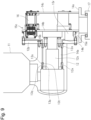
- FIG. 4 is an explanatory diagram of an assembly 40 including the rotation transmission mechanism 15.
- the assembly 40 is integrated by coupling together the external gear 15b of the rotation transmission mechanism 15, the first and second planetary gear mechanisms 20, 30 which are the speed increase mechanism 15c, the generator 16, and the brake 16x.
- the assembly 40 may include a converter 16a.
- the first and second planetary gear mechanisms 20, 30 include sun gears 22, 32, planetary gears 24, 34, planetary carriers 26, 36, and internal gears 28, 38, respectively.
- the external gear 15b is formed along the outer circumferential surface of the internal gear 28 of the first planetary gear mechanism 20, and bearings 20p, 20q are arranged on both axial sides of the external gear 15b. This makes it possible to realize the ultimate miniaturization and weight reduction of the rotation transmission mechanism 15.
- the first and second planetary gear mechanisms 20, 30 are constructed using screw-like gears, it is possible to increase the speed all at once. If the speed increase ratio is the same, the diameter of the sun gears 22, 32 will be equal to the diameter of the sun gear 32a connected to the second stage 30a generator of the normal planetary gear speed increasers 20a, 30a, and in the differential planetary gear mechanisms 20, 30, the speed increase ratio is not affected by the number of teeth of the planetary gears 24, 34 and the sun gears 22, 32, i.e., the reference pitch circle diameter.
- an external gear 15b that engages with the ring gear 15a to distribute rotation and torque and increase the speed can be provided on the internal gear 28.
- the speed increase mechanism 15c can be made extremely small and lightweight.
- the assembly 40 By configuring the assembly 40 into a module, it is possible to mass-produce the same assembly 40, thereby reducing manufacturing costs. For example, when the output is 20 MW and 30 MW, the same module is used, and the number of modules is changed according to the output.
- a bench test can be performed on the assembly 40 to improve the reliability of the assembly 40.
- the wind power generation device 10 includes four assemblies 40
- durability tests of the assemblies 40 can be performed with a small amount of energy by setting two assemblies 40 to driving mode and the other two to regenerative power generation mode. Such durability tests improve the reliability of the assembly 40.
- the assembly 40 has a first housing 40a surrounding the second planetary gear mechanism 30 and a second housing 40b housing the generator 16, the brake 16x, etc.
- the housings 40a, 40b are coupled to each other and disposed between the first and second longitudinal members 14b, 14c fixed to the machine base 14x of the nacelle 14, as shown in Fig. 2(a) .
- the first housing 40a is fixed to the first longitudinal member 14b
- the second housing 40b is fixed to the second longitudinal member 14c.
- the first and second housings 40a, 40b are fixed to the nacelle so as to transmit at least a part of the load acting from the hub 12 to the nacelle 14, and can be used as strength members of the nacelle.
- the housings 40a, 40b of the speed increase mechanism 15c and the generator 16 are often cylindrical, which is an optimal shape for use as strength members.
- the first and second planetary gear mechanisms 20, 30 of the speed increase mechanism 15c of the rotation transmission mechanism 15 may be configured similarly to the differential planetary gear mechanism disclosed in Japanese Patent No. 4,012,940 .
- Fig. 13 is a skeleton diagram of a differential planetary gear mechanism.
- the differential planetary gear mechanism includes one set of planetary gear mechanisms including a sun gear A, a planetary gear B, and an internal gear C, and another set of planetary gear mechanisms including a sun gear D, a planetary gear E, and an internal gear F.
- the sun gears A and D of the two sets of planetary gear mechanisms are connected to each other and rotate together.
- the planetary gears B and E of the two sets of planetary gear mechanisms are connected to each other and rotate together. Only the internal gears C and F of the two sets of planetary gear mechanisms are not connected to each other and can rotate relative to each other.
- the numbers of teeth of gears A, B, C, D, E, and F are Za, Zb, Zc, Zd, Ze, and Zf, respectively.
- the reduction ratio K is given by the following equation 3.
- K Za + Zc ⁇ Zf / Za ⁇ Zf ⁇ Zd ⁇ Zc
- the input and output are interchanged, with the input being the internal gear F and the output being the sun gear A.
- the speed increase ratio is 1/K.
- the differential planetary gear mechanism is configured using screw-like gears as disclosed in Japanese Patent No. 4025806 . That is, as shown in Fig. 4 , the first and second planetary gear mechanisms 20, 30 are configured using screw-like gears.
- the first and second planetary gear mechanisms 20, 30 each include a sun gear 22, 32, a planetary gear 24, 34, a planetary carrier 26, 36, and an internal gear 28, 38.
- the sun gears 22, 32 are coupled to each other and rotate together.
- the planetary gears 24, 34 are coupled to each other and rotate together.
- Z is the number of teeth
- d 1 is the reference pitch circle diameter
- ⁇ t is the front pressure angle
- ⁇ is the reference pitch cylinder helix angle
- the pitch P cannot be changed, but the number n of threads of the lead can be changed, and the helix angle ⁇ is determined.
- the front pressure angle can be changed to allow engaging in the same way as involute gears.
- Table 1 shows an example of the design of the number of teeth.
- Table 1 Planetary gear mechanism with fixed internal teeth Planetary gear mechanism with internal teeth as input Sun Planet Internal teeth Sun Planet Internal teeth Number of teeth symbol Za Zb Zc Zd Ze Zf Number of teeth (multiplier) 7 7 23 8 8 22 Speed increase ratio -22
- the shapes of the axial threads are also equal.
- the speed increase ratio is -22, and the sun gear has a speed increase ratio of 22 times the rotation input of the internal gear when rotating in the opposite direction.
- the first planetary gear mechanism 20 is composed of a screw-like gear with the number of teeth of the "planetary gear mechanism with internal teeth as input” in Table 1
- the second planetary gear mechanism 30 is composed of a screw-like gear with the number of teeth of the "planetary gear mechanism with fixed internal teeth” in Table 1.
- a differential planetary gear mechanism constituted of screw-like gears has a large overlapping engaging ratio and a small number of teeth, so the front module (reference pitch circle/number of teeth) is larger and engagement with extremely high strength is achieved.
- the engaging between the screw-like gears functions as a bearing with high radial and axial strength. Therefore, the sun gears 22, 32 of the first and second planetary gear mechanisms 20, 30 can be held without the use of bearings.
- the input section to which the rotational torque from the external gear 15b is transmitted is the internal gear 28 of the first planetary gear mechanism 20, and the output is the sun gear 32 of the second planetary gear mechanism, and the planetary gears are not used as input or output.
- the planetary gears function as idlers. This makes it possible to greatly reduce the possibility of failure.
- the planetary gear mechanisms 20, 30, which are constituted of screw-like gears, are used as bearings for the rotating body whose speed is increased in the rotation transmission mechanism 15, and since they can transmit rotation without causing slippage, smearing of the bearings can be suppressed.
- Fig. 5 provides explanatory diagrams of the assemblies 42 and 44.
- Fig. 5(a) is a cross-sectional diagram of the assembly 44.
- Fig. 5 (b-1) is a left side diagram of the assembly 42 taken along line I-I in Fig. 5 (b-2).
- Fig. 5 (b-2) is a cross-sectional diagram of the assembly 42.
- Fig. 5 (b-3) is a left side diagram of the assembly 42 taken along line III-III in Fig. 5 (b-2).
- the first assembly 42 is formed by combining and integrating the first and second planetary gear mechanisms 20a, 30a constituting the rotation transmission mechanism 15 with the generator 16 and the brake 16x, etc.
- the first assembly 42 has a housing 43 that houses the first and second planetary gear mechanisms 20a, 30a.
- the first and second planetary gear mechanisms 20a, 30a are composed of spur gears, and each includes a sun gear 22a, 32a, a planetary gear 24a, 34a, a planetary carrier 26a, 36a, and an internal gear 28a, 38a.
- a spline 16x is formed on the planetary carrier 26a of the first planetary gear mechanism 20a.
- the sun gear 22a of the first planetary gear mechanism 20a and the planetary carrier 26a of the planetary gear mechanism 30a are coupled to each other.
- the sun gear 32a of the second planetary gear mechanism 30a is coupled to the rotation shaft of the generator 16.
- the internal gears 28a, 38a of the first and second planetary gear mechanisms 20a, 30a are fixed to a housing 43 of a first assembly 42.
- the second assembly 44 is formed by integrating the first and second plate-shaped holding members 44a, 44b with the external gear 15b disposed between them.
- Bearings 44p, 44q that rotatably support the rotation shaft of the external gear 15b are disposed in the first and second holding members 44a, 44b.
- each of the external gears 15b protrudes radially outward from the outer periphery of the first holding member 44a and can engage with the ring gear 15a.
- the rotation shaft of the external gear 15b protrudes from the second holding member 44b, and a spline 15x is formed on this protruding portion, which can engage with a spline 16x formed on the planet carrier 26a of the first assembly 42.
- the second holding member 44b is fixed to a machine base 14x of the nacelle.
- the first holding member 44a may be coupled to a fixed portion 14a that supports the hub 12.
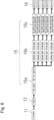
- Fig. 6 is a block diagram of the wind power generation device 10. As shown in Fig. 6 , the wind energy obtained by the blades 11 is branched and distributed into multiple systems by the rotation transmission mechanism 15, and is transmitted to the generators 16 of each system. By branching and distributing in this way, the wind power generation device 10 can take advantage of the increase to the 1.5-th power to achieve weight reduction.
- the rotation speed decreases in proportion to the -0.5-th power of the output.
- the diameter may be increased by the 0.5-th power. If they engage with a diameter that is ⁇ 2 times larger, the increase in speed can cover the decrease in rotation speed.
- the diameter of a distribution type ring gear or external gear drive gear only needs to be ⁇ 2 times larger, which is not proportional to the 1-st power but is ⁇ 2/2 ⁇ 0.7 times, which is less than the increase in output.
- the absolute requirement is that the increase in size and cost must be less than the increase in output. If the output is doubled, the weight and cost must be less than doubled. Only by achieving this can the plant be made larger.
- the wind power generation device 10 can fundamentally solve the problems of the conventional technology by branching and distributing.
- the lubrication of the gears is improved compared to when an external gear is used instead of the ring gear 15a for distribution. Also, if an external gear with a parallel shaft is engaged with the inside of the ring gear, a distribution mechanism with a small overall diameter can be realized, and the size can be reduced.
- the ring gear 15a tends to retain oil inside.
- centrifugal force acts on the oil, causing the oil to move toward the bottom of the ring gear tooth and form an oil pool. This makes it possible to supply oil to the tooth surface that engages with the external gear.
- the oil supply is not as smooth as with the ring gear 15a, and so it is necessary to deal with this by drawing the oil into the bearings and gears.
- the wind power generation device 10 has a large number of gears due to the two-stage planetary gear mechanisms 20, 30, etc., so it is slightly heavier than expected based on the 1.5-th power law, but it can be made smaller and is suitable for mass production.
- the wind power generation device 10 can easily achieve a total speed increase ratio of 100 or more by accelerating the speed while distributing the power, using a small-diameter, lightweight gear mechanism, making the generator much lighter than conventional wind power generation devices.
- the rotation transmission mechanism 15 realizes distribution and speed increase by the ring gear 15a and the external gear 15b.
- a generator 16 with a small output can generate power by directly connecting to the external gear 15b without increasing the rotation speed of the external gear 15b.
- the rotation speed of the hub decreases, so in order to make the generator smaller and lighter, the distributed rotation speed must be increased, for example, by adding one or two stages of a planetary gear mechanism.
- the stress acting on the bearing 13 that is disposed inside the hub 12 and supports the hub 12 is not the stress of a cantilever, and since the rotor is not coupled to the hub 12, the inertia is relatively small, and the failure rate is reduced.
- problems specific to wind power generation with the bearings and the speed increaser after speed increase and there is a risk of damage.
- the torque fluctuation component is the derivative of the torque waveform, so when 1/N•A•cos(N ⁇ t+1) is differentiated, it becomes -A• ⁇ sin(N ⁇ t), and the fluctuation component does not become 1/N. Therefore, when the speed is increased, the amplitude of the basic torque waveform becomes 1/N, but the torque fluctuation component due to wind, etc., becomes A• ⁇ times, and the torque waveform changes as the fluctuation component is amplified and superimposed.
- Fig. 14 is a graph of the frequency distribution of wind. As can be seen from Fig. 14 , wind contains components from 0.1 to several Hertz. As wind turbines become larger, the rotation speed of the hub decreases. For example, if a 20 MW wind turbine rotates at 0.1 Hz, then a 30 MW wind turbine will rotate at about 0.88 Hz.
- the root cause of this is that bearings slide and rotate together, and they move by sliding even when they are not rotating. If the mechanism always rotates, the occurrence of smearing can be suppressed.
- the bearings which is a speed increase mechanism
- the planet carrier is the input shaft, and the sun gear is accelerated and output.
- the revolution of the planetary gear around the sun axis encourages the planetary gear to rotate, so the forces acting between the planet carrier and planetary gear become complex. Therefore, when the rotation fluctuates, the bearings of the planet carrier and planetary gear are affected and often damaged.
- the engaging surfaces of gears are smaller than those of bearings.
- the engaging ratio of normal gears is 3 or less, meaning that there are three or fewer points of contact between the gears. Therefore, fluctuations in rotation are more likely to cause damage to the engaging surfaces of the gears.
- the first and second planetary gear mechanisms 20 and 30 shown in Fig. 3 transmit rotation by engaging of screw-like gears, and are mechanisms that always rotate, so they can suppress smearing. Therefore, they are extremely effective as bearings after speed-up of wind power generation, and can reduce failures of the mechanism.
- Fig. 7 is a cross-sectional diagram of a main part including the rotation transmission mechanism 15z.
- Fig. 8 is an enlarged cross-sectional diagram of a main part of the rotation transmission mechanism 15z.
- the external gears 15j of the multiple rotation transmission mechanisms 15z are disposed inside the ring gear 15i that integrally rotates with the hub 12, and the rotation of the hub 12 is distributed to multiple systems. Note that Fig. 7 shows only one system of the rotation transmission mechanism 15z.
- the ring gear 15i has first and second screw-like internal teeth 15m, 15n which are internal teeth of screw-like gears twisting in opposite directions to each other.
- the external gear 15j has first and second screw-like external teeth 15u, 15v which are external teeth of screw-like gears twisting in opposite directions to each other.
- the first screw-like internal teeth 15m and the first screw-like external teeth 15u engage with each other, and the second screw-like internal teeth 15n and the second screw-like external teeth 15v engage with each other.
- a hollow hole 15h is formed in the external gear 15j, and a pin 15k is inserted and fixed in the hollow hole 15h.
- the external gear 15j is rotatably supported via bearings 15y arranged on both sides of the external gear 15j.
- the bearings 15y are planetary gear mechanisms constituted of screw-like gears, and are configured similarly to the bearings 15x shown in Fig. 4 .
- the bearings 15y can suppress smearing and are highly reliable and durable. However, it is also possible to use a plain bearing, a rolling element bearing, or the like, instead of the bearings 15y.
- the rotation of the external gear 15 j is accelerated by a speed increase mechanism 15 w and then transmitted to the generator 16 .
- the speed increase mechanism 15w includes first and second planetary gear mechanisms composed of screw-like gears, similar to the speed increase mechanism 15c shown in Fig. 4 .
- the first and second planetary gear mechanisms 20, 30 include sun gears 22, 32, planetary gears 24, 34, and internal gears 28, 38, respectively.
- the sun gears 22, 32 are coupled to each other and rotate together.
- the planetary gears 24, 34 are coupled to each other, rotatably supported by the planetary carrier 26 , and rotate together.
- the planetary carrier 26 is coupled to the rotation shaft of the small gear 15j via a spline
- the sun gear shaft is coupled to the rotation shaft of the generator 16 via a spline 16r.
- the engaging ratio can be increased, and the rotation can be transmitted smoothly.
- the thrust force can be canceled and the thrust force acting on the rotation transmission mechanism 15z can be suppressed.
- the screw-like gears can easily increase the permissible engaging angle ⁇ g , it is easy to configure the rotation transmission mechanism 15z so that no excessive force is applied to the engaging between the large gear 15i and the small gear 15j.
- Fig. 9 is an explanatory diagram of a wind power generation device, and the same reference numerals as in Example 1 are used to designate the same components as in Example 1.
- the hub 12 is rotatably supported via a pair of bearings 13x.
- the bearing 13x includes an inner ring 13p and an outer ring 13q that are rotatable relative to one another, and the inner ring 13p is fixed to a fixed portion 14a, and the outer ring 13q is fixed to the hub 12.
- a pair of bearings 13x having tapered (conical) bearing surfaces 13s, 13t are used, but it is also possible to use a plain bearing with a cylindrical bearing surface and provide a thrust bearing if necessary.
- Plain bearings are resistant to vibration and shock loads, have a simple structure, and can be installed in a space-saving manner. However, they tend to have higher friction loss than rolling element bearing, so good oil lubrication and maintenance are essential.
- wind turbines are becoming larger, and the fluctuations in the wind that the blades receive cause vibration and shock loads to be applied to the main bearings, resulting in frequent failures.
- attempts are being made to adopt plain bearings for the main bearings.
- the bearings 13 and 13x are completely separate members from the fixed portion 14a and the hub 12.
- the portions corresponding to all or part of the inner rings 13a and 13p of the bearings 13 and 13x may be formed on the fixed portion 14a, and the portions corresponding to all or part of the outer rings 13b and 13q of the bearings 13 and 13x may be formed on the hub 14a.
- the portion corresponding to the bearing surface 13s of the inner ring 13p of the plain bearing 13x may be formed on the fixed portion 14a.
- the portion corresponding to the bearing surface 13t of the outer ring 13q of the plain bearing 13x may be formed on the hub 12.
- the bearings 13, 13x that rotatably support the hub 12 may be of an appropriate type and shape and may be disposed at appropriate locations between the hub 12 and the fixed portion 12a of the nacelle 12.
- they are not limited to the rolling element bearing 13 and the plain bearing 13x, but it is also possible to use a composite bearing, a magnetic bearing, an oil-retaining bearing, a ceramic bearing, or the like.
- the wind power generation device described above can be made large while suppressing increases in cost.
- Example 1 and Modification Examples 1-4 may be appropriately combined.
Landscapes
- Engineering & Computer Science (AREA)
- General Engineering & Computer Science (AREA)
- Life Sciences & Earth Sciences (AREA)
- Sustainable Energy (AREA)
- Mechanical Engineering (AREA)
- Sustainable Development (AREA)
- Chemical & Material Sciences (AREA)
- Combustion & Propulsion (AREA)
- Power Engineering (AREA)
- Wind Motors (AREA)
- Retarders (AREA)
- Connection Of Motors, Electrical Generators, Mechanical Devices, And The Like (AREA)
Applications Claiming Priority (2)
| Application Number | Priority Date | Filing Date | Title |
|---|---|---|---|
| JP2022126715A JP7240777B1 (ja) | 2022-08-08 | 2022-08-08 | 風力発電装置 |
| PCT/JP2023/026454 WO2024034342A1 (ja) | 2022-08-08 | 2023-07-19 | 風力発電装置 |
Publications (2)
| Publication Number | Publication Date |
|---|---|
| EP4549731A1 true EP4549731A1 (de) | 2025-05-07 |
| EP4549731A4 EP4549731A4 (de) | 2025-11-12 |
Family
ID=85570581
Family Applications (1)
| Application Number | Title | Priority Date | Filing Date |
|---|---|---|---|
| EP23852321.1A Pending EP4549731A4 (de) | 2022-08-08 | 2023-07-19 | Windenergieerzeugungsvorrichtung |
Country Status (5)
| Country | Link |
|---|---|
| EP (1) | EP4549731A4 (de) |
| JP (2) | JP7240777B1 (de) |
| KR (1) | KR20250029251A (de) |
| CN (1) | CN119654488A (de) |
| WO (1) | WO2024034342A1 (de) |
Family Cites Families (8)
| Publication number | Priority date | Publication date | Assignee | Title |
|---|---|---|---|---|
| JPS5757118Y2 (de) | 1978-07-08 | 1982-12-08 | ||
| JPH08177711A (ja) | 1994-12-22 | 1996-07-12 | Mitsubishi Heavy Ind Ltd | 大容量風力発電用増速機 |
| JP3574377B2 (ja) * | 2000-06-05 | 2004-10-06 | 株式会社きんでん | 風力発電装置 |
| CN100585220C (zh) | 2004-06-22 | 2010-01-27 | 杉谷伸 | 齿轮机构、行星齿轮装置、旋转轴承装置、及奇异行星齿轮减速装置 |
| WO2007017935A1 (ja) | 2005-08-10 | 2007-02-15 | Nobuyoshi Sugitani | 遊星歯車装置 |
| DE102007048377A1 (de) * | 2007-10-09 | 2009-04-16 | Schaeffler Kg | Lageranordnung einer Rotornabe einer Windenergieanlage und Verfahren zu deren Montage |
| JP5832139B2 (ja) * | 2011-05-11 | 2015-12-16 | 株式会社Wind−Smile | 風力発電装置 |
| JP5834282B2 (ja) * | 2011-09-14 | 2015-12-16 | イマデスト株式会社 | 遊星式回転−直線運動変換装置 |
-
2022
- 2022-08-08 JP JP2022126715A patent/JP7240777B1/ja active Active
-
2023
- 2023-07-19 EP EP23852321.1A patent/EP4549731A4/de active Pending
- 2023-07-19 WO PCT/JP2023/026454 patent/WO2024034342A1/ja not_active Ceased
- 2023-07-19 CN CN202380057853.6A patent/CN119654488A/zh active Pending
- 2023-07-19 KR KR1020257003664A patent/KR20250029251A/ko active Pending
- 2023-07-19 JP JP2024520073A patent/JP7550504B2/ja active Active
Also Published As
| Publication number | Publication date |
|---|---|
| JP2024023106A (ja) | 2024-02-21 |
| KR20250029251A (ko) | 2025-03-04 |
| CN119654488A (zh) | 2025-03-18 |
| JP7240777B1 (ja) | 2023-03-16 |
| JP7550504B2 (ja) | 2024-09-13 |
| JPWO2024034342A1 (de) | 2024-02-15 |
| WO2024034342A1 (ja) | 2024-02-15 |
| EP4549731A4 (de) | 2025-11-12 |
Similar Documents
| Publication | Publication Date | Title |
|---|---|---|
| KR100823772B1 (ko) | 풍력 발전용 풍차 | |
| US8358029B2 (en) | Rotor-shaft integrated generator drive apparatus | |
| EP2108082B1 (de) | Windturbine mit antriebsstrang | |
| US8951162B1 (en) | Drive train transmission | |
| EP2191130B1 (de) | Lagerzahnräder für windturbinenanwendungen | |
| US9388796B2 (en) | Assembly for extracting the rotational energy from the rotor hub of the wind turbine of a wind turbine system | |
| Cotrell | A preliminary evaluation of a multiple-generator drivetrain configuration for wind turbines | |
| EP3181899A1 (de) | Windturbine mit modularem antriebsstrang | |
| EP3662159B1 (de) | Planetenträger eines windturbinengetriebes mit verbessertem schmiermittelweg | |
| US20120091725A1 (en) | Wind turbine generator | |
| US9028361B2 (en) | Modular gear unit for a wind turbine | |
| KR20220087524A (ko) | 풍력 터빈 | |
| CN202194785U (zh) | 一种水平轴风力机组及其齿轮箱装置 | |
| CN113803216B (zh) | 风力发电机组 | |
| US9316290B2 (en) | Epicyclic gearing with a gearing housing | |
| JP5287631B2 (ja) | 風力発電装置 | |
| JP7550504B2 (ja) | 風力発電装置 | |
| JP5156028B2 (ja) | 風力発電装置のピッチ駆動装置および風力発電装置 | |
| CA3263519A1 (en) | Wind power generation device | |
| EP4077927A1 (de) | Windturbine und kraftübertragungssystem dafür | |
| KR20100047131A (ko) | 듀얼 로터 풍력발전기 | |
| WO2025020079A1 (en) | A drivetrain for a wind turbine and a wind turbine | |
| EP2045463A1 (de) | Windkraftanlage | |
| DK202070052A1 (en) | Wind turbine power transmission system |
Legal Events
| Date | Code | Title | Description |
|---|---|---|---|
| STAA | Information on the status of an ep patent application or granted ep patent |
Free format text: STATUS: THE INTERNATIONAL PUBLICATION HAS BEEN MADE |
|
| PUAI | Public reference made under article 153(3) epc to a published international application that has entered the european phase |
Free format text: ORIGINAL CODE: 0009012 |
|
| STAA | Information on the status of an ep patent application or granted ep patent |
Free format text: STATUS: REQUEST FOR EXAMINATION WAS MADE |
|
| 17P | Request for examination filed |
Effective date: 20250203 |
|
| AK | Designated contracting states |
Kind code of ref document: A1 Designated state(s): AL AT BE BG CH CY CZ DE DK EE ES FI FR GB GR HR HU IE IS IT LI LT LU LV MC ME MK MT NL NO PL PT RO RS SE SI SK SM TR |
|
| A4 | Supplementary search report drawn up and despatched |
Effective date: 20251014 |
|
| DAV | Request for validation of the european patent (deleted) | ||
| DAX | Request for extension of the european patent (deleted) | ||
| RIC1 | Information provided on ipc code assigned before grant |
Ipc: F03D 15/00 20160101AFI20251008BHEP Ipc: F03D 1/06 20060101ALI20251008BHEP Ipc: F03D 80/80 20160101ALI20251008BHEP Ipc: F16H 1/28 20060101ALI20251008BHEP Ipc: H02K 7/116 20060101ALI20251008BHEP Ipc: H02K 7/18 20060101ALI20251008BHEP |
|
| STAA | Information on the status of an ep patent application or granted ep patent |
Free format text: STATUS: EXAMINATION IS IN PROGRESS |
|
| 17Q | First examination report despatched |
Effective date: 20260506 |