EP4549792A1 - Ensemble bobine et électro-vanne - Google Patents
Ensemble bobine et électro-vanne Download PDFInfo
- Publication number
- EP4549792A1 EP4549792A1 EP23830408.3A EP23830408A EP4549792A1 EP 4549792 A1 EP4549792 A1 EP 4549792A1 EP 23830408 A EP23830408 A EP 23830408A EP 4549792 A1 EP4549792 A1 EP 4549792A1
- Authority
- EP
- European Patent Office
- Prior art keywords
- control board
- electric control
- coil assembly
- end portion
- housing portion
- Prior art date
- Legal status (The legal status is an assumption and is not a legal conclusion. Google has not performed a legal analysis and makes no representation as to the accuracy of the status listed.)
- Pending
Links
Images





Classifications
-
- F—MECHANICAL ENGINEERING; LIGHTING; HEATING; WEAPONS; BLASTING
- F16—ENGINEERING ELEMENTS AND UNITS; GENERAL MEASURES FOR PRODUCING AND MAINTAINING EFFECTIVE FUNCTIONING OF MACHINES OR INSTALLATIONS; THERMAL INSULATION IN GENERAL
- F16K—VALVES; TAPS; COCKS; ACTUATING-FLOATS; DEVICES FOR VENTING OR AERATING
- F16K31/00—Actuating devices; Operating means; Releasing devices
- F16K31/02—Actuating devices; Operating means; Releasing devices electric; magnetic
- F16K31/04—Actuating devices; Operating means; Releasing devices electric; magnetic using a motor
- F16K31/046—Actuating devices; Operating means; Releasing devices electric; magnetic using a motor with electric means, e.g. electric switches, to control the motor or to control a clutch between the valve and the motor
-
- F—MECHANICAL ENGINEERING; LIGHTING; HEATING; WEAPONS; BLASTING
- F16—ENGINEERING ELEMENTS AND UNITS; GENERAL MEASURES FOR PRODUCING AND MAINTAINING EFFECTIVE FUNCTIONING OF MACHINES OR INSTALLATIONS; THERMAL INSULATION IN GENERAL
- F16K—VALVES; TAPS; COCKS; ACTUATING-FLOATS; DEVICES FOR VENTING OR AERATING
- F16K31/00—Actuating devices; Operating means; Releasing devices
- F16K31/02—Actuating devices; Operating means; Releasing devices electric; magnetic
- F16K31/04—Actuating devices; Operating means; Releasing devices electric; magnetic using a motor
-
- F—MECHANICAL ENGINEERING; LIGHTING; HEATING; WEAPONS; BLASTING
- F16—ENGINEERING ELEMENTS AND UNITS; GENERAL MEASURES FOR PRODUCING AND MAINTAINING EFFECTIVE FUNCTIONING OF MACHINES OR INSTALLATIONS; THERMAL INSULATION IN GENERAL
- F16K—VALVES; TAPS; COCKS; ACTUATING-FLOATS; DEVICES FOR VENTING OR AERATING
- F16K1/00—Lift valves or globe valves, i.e. cut-off apparatus with closure members having at least a component of their opening and closing motion perpendicular to the closing faces
- F16K1/02—Lift valves or globe valves, i.e. cut-off apparatus with closure members having at least a component of their opening and closing motion perpendicular to the closing faces with screw-spindle
-
- F—MECHANICAL ENGINEERING; LIGHTING; HEATING; WEAPONS; BLASTING
- F16—ENGINEERING ELEMENTS AND UNITS; GENERAL MEASURES FOR PRODUCING AND MAINTAINING EFFECTIVE FUNCTIONING OF MACHINES OR INSTALLATIONS; THERMAL INSULATION IN GENERAL
- F16K—VALVES; TAPS; COCKS; ACTUATING-FLOATS; DEVICES FOR VENTING OR AERATING
- F16K1/00—Lift valves or globe valves, i.e. cut-off apparatus with closure members having at least a component of their opening and closing motion perpendicular to the closing faces
- F16K1/32—Details
- F16K1/34—Cutting-off parts, e.g. valve members, seats
- F16K1/36—Valve members
- F16K1/38—Valve members of conical shape
-
- F—MECHANICAL ENGINEERING; LIGHTING; HEATING; WEAPONS; BLASTING
- F16—ENGINEERING ELEMENTS AND UNITS; GENERAL MEASURES FOR PRODUCING AND MAINTAINING EFFECTIVE FUNCTIONING OF MACHINES OR INSTALLATIONS; THERMAL INSULATION IN GENERAL
- F16K—VALVES; TAPS; COCKS; ACTUATING-FLOATS; DEVICES FOR VENTING OR AERATING
- F16K27/00—Construction of housing; Use of materials therefor
- F16K27/02—Construction of housing; Use of materials therefor of lift valves
- F16K27/029—Electromagnetically actuated valves
-
- F—MECHANICAL ENGINEERING; LIGHTING; HEATING; WEAPONS; BLASTING
- F16—ENGINEERING ELEMENTS AND UNITS; GENERAL MEASURES FOR PRODUCING AND MAINTAINING EFFECTIVE FUNCTIONING OF MACHINES OR INSTALLATIONS; THERMAL INSULATION IN GENERAL
- F16K—VALVES; TAPS; COCKS; ACTUATING-FLOATS; DEVICES FOR VENTING OR AERATING
- F16K31/00—Actuating devices; Operating means; Releasing devices
- F16K31/02—Actuating devices; Operating means; Releasing devices electric; magnetic
- F16K31/06—Actuating devices; Operating means; Releasing devices electric; magnetic using a magnet, e.g. diaphragm valves, cutting off by means of a liquid
- F16K31/0675—Electromagnet aspects, e.g. electric supply therefor
- F16K31/0679—Electromagnet aspects, e.g. electric supply therefor with more than one energising coil
Definitions
- the present application relates to the technical field of fluid control, and in particular to a coil assembly and an electric valve.
- An electric valve includes a coil assembly, which includes a stator component, a control box and an electric control board.
- the electric control board is located in a space formed by the control box, and the control box includes a first housing portion and a second housing portion that are fixedly connected to each other.
- the first housing portion is provided with an insertion port portion, and the insertion port portion is provided with an insertion pin to be in an electrical connection or signal connection to an external device.
- the first housing portion is integrally formed on an injection molding body that is formed on a periphery of the stator component by injection molding, or may be fixed on the injection molding body by other means. When the number of the insertion pin needs to be changed, it is necessary to redevelop the first housing portion or a combination of the first housing portion and the stator component, which may increase the development cost of the coil assembly or the electric valve.
- An object of the present application is to provide a coil assembly and an electric valve, which is beneficial to simplifying the assembly of the coil assembly and reducing the development cost of the coil assembly or the electric valve.
- a coil assembly includes a control box, a stator component and an electric control board.
- the control box is provided with a first chamber, and the electric control board is located in the first chamber.
- the stator component is provided with a first insertion pin that is connected to the electric control board.
- the control box includes a first housing portion and a second housing portion that are fixedly connected to each other.
- the second housing portion includes an insertion port portion and a first connector, and the insertion port portion is provided with a second chamber.
- the first connector is provided with a first end portion and a second end portion. A part of the first end portion is located in the first chamber, and a part of the second end portion is located in the second chamber.
- the first end portion is connected to the electric control board by press-fit, and the first connector is configured to be in an electrical connection and/or signal connection to the electric control board.
- An electric valve includes the coil assembly described hereinabove, a valve component and a valve body block.
- the valve component is fixedly connected to the valve body block, and the coil assembly is fixedly connected to the valve body block or the valve component.
- the control box includes the first housing portion and the second housing portion that are fixedly connected to each other.
- the second housing portion includes the insertion port portion and the first connector, and the insertion port portion is provided with the second chamber.
- the first connector is provided with the first end portion and the second end portion. A part of the first end portion is located in the first chamber, and a part of the second end portion is located in the second chamber.
- the first end portion is connected to the electric control board by press-fit, and the first connector is configured to be in an electrical connection and/or signal connection to the electric control board.
- FIGS. 1 to 3 illustrate a first embodiment of a coil assembly 100.
- the coil assembly 100 includes a control box 1, a stator component 2 and an electric control board 3.
- the control box 1 is provided with a first chamber 13, and the electric control board 3 is located in the first chamber 13.
- the stator component 2 is provided with first insertion pins 21 that are connected to the electric control board 3.
- the first insertion pins 21 are fixed to the electric control board 3 by welding.
- the fixation may be achieved by press-fit through press-fit pins, or by other means.
- One end of some of the first insertion pins 21 is connected to a winding inside the stator component 2, and the other end is connected to the electric control board 3.
- the number of the first insertion pins 21 may be determined according to needs.
- the control box 1 includes a first housing portion 11 and a second housing portion 12 that are fixedly connected to each other.
- the coil assembly 100 includes an injection molding portion 4 that covers at least a part of the stator component 2.
- the injection molding portion 4 and the first housing portion 11 are integrally formed by injection molding.
- the injection molding portion 4 and the first housing portion 11 may be separately formed, and are then fixed to each other by welding or engagement, or by a screw.
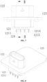
- the second housing portion 12 includes a first connector 121 and an insertion port portion 122.
- the insertion port portion 122 is provided with a second chamber 1221, and the first connector 121 is provided with a first end portion 1211 and a second end portion 1212. A part of the first end portion 1211 is located in the first chamber 13, and a part of the second end portion 1212 is located in the second chamber 1221.
- the first end portion 1211 is connected to the electric control board 3 by press-fitting.
- the first end portion 1211 of the first connector 121 can be in an electrical connection or a signal connection to the electric control board 3, and the second end portion 1212 of the first connector 121 is configured to be in an electrical connection or a signal connection to an external device.
- the first end portion 1211 is connected to the electric control board 3 by press-fit, so as to simplify the connection between the first connector 121 and the electric control board 3, thereby simplifying the connection between the first housing portion 11 and the second housing portion 12.
- the electric control board 3 when changing the number of the first connector 121, there is no need to redesign the first housing portion 11 or a combination of the first housing portion 11 and the stator component 2.
- the only thing needed is a small change to the second housing portion 12 and the electric control board 3, such as changing the number of the first connector 121. That is, it is unnecessary to redevelop or redesign the entire coil assembly, which is beneficial to reducing the development cost of the coil assembly 100.
- the electric control board 3 is arranged above the stator component 2, and a direction parallel to the electric control board 3 is defined as a horizontal direction.
- the directions in the present application only indicate relative positions.
- the first housing portion 11 and the second housing portion 12 are fixed to each other by welding, such as laser welding, ultrasonic welding and the like.
- the first housing portion 11 and the second housing portion 12 are fixed to each other by laser welding, and are sealed by welding.
- a seal may be further provided between the first housing portion 11 and the second housing portion 12.
- the first housing portion 11 and the second housing portion 12 may be fixedly connected to each other by snap-fit, and may be sealed by a seal that is provided between the first housing portion 11 and the second housing portion 12.
- the second housing portion 12 further includes a plate body portion 123, and the second housing portion 12 is fixedly connected to the first housing portion 11 through the plate body portion 123.
- the plate body portion 123 and the insertion port portion 122 are integrally formed by injection molding.
- the number of the first connector 121 may be determined according to needs.
- the number of the first connector 121 may be 3, 4, or 5.
- a main body of each first connector 121 is made of a metallic material, which is conductive.
- the second housing portion 12 is integrally formed by injection molding with the first connectors 121 being injection molding inserts.
- each first connector 121 between the first end portion 1211 and the second end portion 1212 of the first connector 121 is covered by an injection molding material.
- the first connectors 121 are fixedly connected to the insertion port portion 122 by injection molding.
- each first connector 121 includes a transition portion 1213, and at least a part of the transition portion 1213 is covered by the injection molding material.
- the first connectors 121 may be fixed to the insertion port portion 122 in a way other than injection molding.
- the first connectors 121 may be preformed into a row by injection molding, i.e., formed into a pin header fixed by an injection molded connecting portion.
- the injection molded connecting portion covers the transition portions 1213 between the first end portions 1211 and the second end portions 1212, and the insertion port portion 122 is provided with multiple through holes for the first end portions 1211 to pass through, or provided with a through hole for the injection molded connecting portion to pass through.
- the connection strength and sealing between the first connectors 121 and the insertion port portion 122 may be further enhanced by adhesive bonding, welding or the like.
- the first connectors 121 are preformed into a row by injection molding
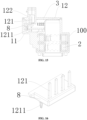
- the injection molding assembly 8 includes the first connectors 121 and the injection molded connecting portion.
- the insertion port portion 122 is provided with multiple through holes 1222 for the first end portions 1211 of the first connectors 121 to pass through. Certainly, after the first end portions 1211 pass through the through holes 1222, gaps between the first end portions 1211 and the through holes may be sealed by adhesive bonding, welding, potting or the like, which can also enhance the connection strength.
- the injection molding 8 and the electric control board 3 are assembled first. Then the second housing portion 12 is assembled with the first housing portion 11. When the second housing portion 12 is assembled, the first end portions 1211 of the first connectors 121 pass through the through holes 1222 of the insertion port portion 122.
- the first end portions 1211 are connected to the electric control board 3 by press-fit, and the first connectors 121 can be in electrical connections or signal connections to the electric control board 3.
- Other structures may refer to other embodiments described hereinabove or hereinafter.
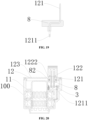
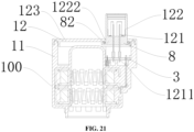
- the first connectors 121 are preformed into a row by injection molding, the first connectors 121 are preformed into a row by injection molding to form an injection molding assembly 8.
- the injection molding assembly 8 includes the first connectors 121 and the injection molded connecting portion.
- the insertion port portion 122 is provided with a through hole 1222 for the injection molding assembly 8 to pass through.
- the injection molding assembly 8 passes through the through hole, and is connected to the insertion port portion 122 in a fixed or limited manner.
- the injection molding assembly 8 and the second housing portion 12 are assembled first. After that, the injection molding assembly 8 and the second housing portion 12 are fit with the first housing portion 11 and the electric control board 3.
- a seal 82 may be further provided between the injection molding assembly 8 and the insertion port portion 122 for sealing.
- the first end portions 1211 are connected to the electric control board 3 by press-fitting, and the first connectors 121 can be in electrical connections or signal connections to the electric control board 3.
- Other structures may refer to other embodiments described hereinabove or hereinafter.
- each first end portion 1211 is in a form of a press-fit pin.
- the first end portion 1211 is provided with a first eye portion 1214, and the first eye portion 1214 is provided with a first eye hole 1215.
- the electric control board 3 is provided with a first through hole 31, and the first end portion 1211 is connected to the electric control board 3 by press-fit through the first eye portion 1214.
- the first eye portion 1214 is press-fitted into the first through hole 31, making the first eye hole 1215 retracts and deforms, and the first eye portion 1214 is in interference fit with a wall of the first through hole 31 after press-fitting.
- the wall of the first through hole 31 is made of a metallic material, so that the first connector 121 can be electrically connected to the electric control board 3. With such arrangements, it is possible to simplify the connection between the first connectors 121 and the electric control board 3, thereby simplifying the mounting of the second housing portion 12 to the first housing portion 11.
- the second housing portion 12 is provided with multiple limiting portions 124 that protrude downwards from a lower end face of the second housing portion 12.
- the limiting portions 124 protrude downwards from a lower end face of the insertion port portion 122.
- Each of the limiting portions 124 is located between adjacent first end portions 1211 or relatively close to the first end portions 1211.
- the limiting portions 124 may be formed by injection molding and cover an upper portion of the first end portions 1211.
- the first housing portion 11 is further provided with a first support portion 111, a second support portion 112 and a third support portion 113.
- the first housing portion 11 further includes a first side wall portion 115, a second side wall portion 116 and a third side wall portion 117.
- the first side wall portion 115 and the second side wall portion 116 are arranged opposite to each other, and the third side wall portion 117 is connected to the first side wall portion 115 and the second side wall portion 116.
- the first support portion 111 is arranged close to the first side wall portion 115
- the second support portion 112 is arranged close to the second side wall portion 116.
- the first support portion 111 and the second support portion 112 are symmetric to each other, and the third support portion 113 is arranged close to the third side wall portion 117.
- the electric control board 3 abuts against the first support portion 111, the second support portion 112 and the third support portion 113, which are located at different positions to stably support the electric control board 3.
- the first housing portion 11 further includes a fourth support portion 114, and the third support portion 113 is located between the first end portions 1211 and the third side wall portion 117.
- the third support portion 113 is located on one side of the first end portions 1211 close to the third side wall portion 117, and the fourth support portion 114 is located on the other side of the first end portion 1211 away from the third side wall portion 117.
- the third support portion 113 is located on a right side of the first end portions 1211 in FIG. 3
- the fourth support portion 114 is located on a left side of the first end portion 1211 in FIG. 3 .
- the electric control board 3 abuts against the fourth support portion 114.
- the first housing portion 11 is provided with a first groove 118 that is located between the third support portion 113 and the fourth support portion 114, and a part of each first end portion 1211 passing out of the electric control board 3 is accommodated in the first groove 118. With such arrangements, the first end portions 1211 will not be interfered with. Furthermore, the third support portion 113 and the fourth support portion 114 are both provided, so that the electric control board 3 can be prevented from being damaged by pressure during press-fitting. In the present embodiment, an opening of the insertion port portion 122 faces upwards.
- the coil assembly 100 has a shorter length in the horizontal direction, and a female connector of the external device in cooperation with the insertion port portion 122 can be fit with the insertion port portion 122 in a downward direction, which can prevent the coil assembly 100 from interfering with components in the horizontal direction.
- the opening of the insertion port portion 122 may faces horizontally according to needs.
- the first housing portion 11 further includes multiple positioning portions 1111 that are arranged close to the third side wall portion 117.
- the electric control board 3 is provided with a positioning groove 32, and a part of each positioning portion 1111 is accommodated in the positioning groove 32.
- the positioning portions 1111 cooperate with the positioning groove 32 to provide positioning for the mounting of the electric control board 3, so as to improve the mounting precision of the electric control board 3.
- the number of the positioning portions 1111 is two, and the two positioning portions 1111 are symmetric to each other, which is beneficial to balancing the external forces applied on the electric control board 3.
- the first housing portion 11 is provided with multiple positioning columns 119
- the second housing portion 12 is provided with positioning hole columns 125, the number of which is the same as the number of the positioning columns 119.
- Each of the positioning hole columns 125 is provided with a positioning hole (not shown in the drawings) with an opening facing downwards.
- the positioning hole columns 125 are located on the lower end face of the second housing portion 12, and an upper end portion of each of the positioning columns 119 is located in a corresponding one of the positioning holes.
- the positioning column 119 is in contact or clearance fit with a side wall of the corresponding positioning hole to limit relative positions of the first housing portion 11 and the second housing portion 12 in the horizontal direction.
- the number of the positioning columns 119 is two, and the two positioning columns 119 are symmetric to each other.
- the positioning hole columns 125 may not be provided, and recessed positioning holes are directly formed on a lower surface of the second housing portion 12.
- each first end portion 1211 is columnar.
- a guide portion is provided at an end of the first end portion 1211 close to the electric control board 3, and the electric control board 3 is provided with first through holes 31.
- the first end portion 1211 is connected to the electric control board 3 by press-fit.
- the first end portion 1211 is press-fitted into a corresponding one of the first through holes 31, and is in interference fit with a wall of the corresponding first through hole 31.
- An outer diameter of the guide portion decreases in a direction towards the electric control board 3, and the guide portion guides the press-fitting of the first end portion 1211.
- the electric control board 3 is provided with elastic sockets (not shown in the drawings).
- the first end portion 1211 is connected to the electric control board 3 by press-fitting through a corresponding one of the elastic sockets.
- the first end portion 1211 is press-fitted into the elastic socket, making the elastic socket expand, and the first end portion 1211 is in tight contact with an inner wall of the elastic socket.
- the elastic socket may consist of multiple elastic metal sheets forming a structure that has a flower-like shape.
- an embodiment of an electric valve 101 is further provided according to the present application.
- the electric valve 101 includes the above coil assembly 100, and further includes a valve component 5 and a valve body block 6 that are fixedly connected to each other.
- the coil assembly 100 is connected to the valve body block 6 in a fixed or detachable manner.
- the fixed connection includes a connection by a screw, a fixation by engagement and the like.
- the coil assembly 100 is fixedly connected to the valve component 5.
- the coil assembly 100 and the valve component 5, as a whole, are connected to the valve body block 6 in a fixed or detachable manner.
- the valve core assembly 53 is in threaded fit with the nut assembly 54, so that the rotation of the rotor assembly 52 is converted into an axial movement of the valve core assembly 53 relative to the valve seat component 51.
- the valve seat component 51 is provided with a valve port 511.
- the valve core assembly 53 can regulate a flow area of the valve port 511, thereby regulating a flow rate of a working medium flowing through the valve port 511.
- the electric valve further includes a connecting component 7, and the connecting component 7 includes a connecting plate 71 and an engagement portion 72.
- the connecting plate 71 is fixedly connected to the coil assembly 100 by hot riveting, ultrasonic welding or the like.
- the engagement portion 72 is elastic, and the connecting component 7 is detachably connected to the valve body block 6 through the engagement portion 72.
- the engagement portion 72 includes a hook 721 and a disconnection portion 722.
- the hook 721 is in fit with the valve body block 6 to prevent the coil assembly 100 from being separated from the valve body block 6.
- An external tool cooperates with the disconnection portion 722 to pull up the engagement portion 72, so that the coil assembly 100 can be separated from the valve body block 6.
- valve body block 6 is formed separately.
- the valve body block 6 may be a part of another component, such as a part of a connecting part of an integrated assembly, or a part of a heat exchange assembly.
- the second housing portion 12 includes a plate body portion 123 and an insertion port portion 122.
- the second housing portion 12 is fixedly connected to the first housing portion 11 through the plate body portion 123.
- the plate body portion 123 and the insertion port portion 122 are separate structures that are fixedly connected to each other by welding, riveting, or both riveting and welding, or riveting in combination with adhesive bonding, etc.
- the plate body portion 123 is provided with a through hole 1222, and the insertion port portion 122 can pass through the plate body portion 123.
- a seal 82 may be further provided between the insertion port portion 122 and the plate body portion 123 for sealing.
- the insertion port portion 122 is formed by injection molding with the first connectors 121 being injection molding inserts, and a part between the first end portion 1211 and the second end portion 1212 is covered by the injection molding material.
- the first end portions 1211 are connected to the electric control board 3 by press-fitting, and the first connectors 121 can be in electrical connections or signal connections to the electric control board 3. If the first connectors 121 are damaged, only the second housing portion 12, including the insertion port portion 122 and the first connectors 121, needs to be replaced. In this way, the maintenance cost is reduced, and the maintenance of the coil assembly 100 is facilitated.
- first connectors 121 needs to be changed, only the second housing portion 12, including the insertion port portion 122 and the first connectors 121, needs to be redesigned. There is no need to redevelop a new product, which helps to reduce the development cost.
Landscapes
- Engineering & Computer Science (AREA)
- General Engineering & Computer Science (AREA)
- Mechanical Engineering (AREA)
- Physics & Mathematics (AREA)
- Electromagnetism (AREA)
- Magnetically Actuated Valves (AREA)
- Valve Housings (AREA)
- Electrically Driven Valve-Operating Means (AREA)
Applications Claiming Priority (3)
| Application Number | Priority Date | Filing Date | Title |
|---|---|---|---|
| CN202210773656 | 2022-07-01 | ||
| CN202210882659.9A CN117489791A (zh) | 2022-07-26 | 2022-07-26 | 一种控制装置及电动阀 |
| PCT/CN2023/103858 WO2024002240A1 (fr) | 2022-07-01 | 2023-06-29 | Ensemble bobine et électro-vanne |
Publications (1)
| Publication Number | Publication Date |
|---|---|
| EP4549792A1 true EP4549792A1 (fr) | 2025-05-07 |
Family
ID=89383281
Family Applications (1)
| Application Number | Title | Priority Date | Filing Date |
|---|---|---|---|
| EP23830408.3A Pending EP4549792A1 (fr) | 2022-07-01 | 2023-06-29 | Ensemble bobine et électro-vanne |
Country Status (4)
| Country | Link |
|---|---|
| EP (1) | EP4549792A1 (fr) |
| JP (1) | JP2025519964A (fr) |
| KR (1) | KR20250025466A (fr) |
| WO (1) | WO2024002240A1 (fr) |
Family Cites Families (9)
| Publication number | Priority date | Publication date | Assignee | Title |
|---|---|---|---|---|
| CH683575A5 (fr) * | 1990-10-11 | 1994-03-31 | Honeywell Lucifer Sa | Ensemble d'électroaimants pour électrovalves à commande directe. |
| JP6518713B2 (ja) * | 2017-04-12 | 2019-05-22 | 株式会社不二工機 | 電動弁 |
| CN208900796U (zh) * | 2018-06-15 | 2019-05-24 | 杭州三花研究院有限公司 | 电动阀 |
| CN113154114A (zh) * | 2018-06-15 | 2021-07-23 | 杭州三花研究院有限公司 | 电动阀 |
| US11619317B2 (en) * | 2018-06-15 | 2023-04-04 | Zhejiang Sanhua Intelligent Controls Co., Ltd. | Electrically operated valve |
| CN110735959B (zh) * | 2018-07-20 | 2022-04-08 | 浙江三花智能控制股份有限公司 | 一种电子膨胀阀以及热管理组件 |
| CN111911697A (zh) * | 2019-05-07 | 2020-11-10 | 杭州三花研究院有限公司 | 电子膨胀阀 |
| JP7462282B2 (ja) * | 2019-08-22 | 2024-04-05 | 株式会社テージーケー | 電動弁 |
| CN114542755A (zh) * | 2020-11-25 | 2022-05-27 | 浙江三花汽车零部件有限公司 | 电磁阀 |
-
2023
- 2023-06-29 EP EP23830408.3A patent/EP4549792A1/fr active Pending
- 2023-06-29 KR KR1020257001980A patent/KR20250025466A/ko active Pending
- 2023-06-29 WO PCT/CN2023/103858 patent/WO2024002240A1/fr not_active Ceased
- 2023-06-29 JP JP2024575844A patent/JP2025519964A/ja active Pending
Also Published As
| Publication number | Publication date |
|---|---|
| WO2024002240A1 (fr) | 2024-01-04 |
| JP2025519964A (ja) | 2025-06-26 |
| KR20250025466A (ko) | 2025-02-21 |
Similar Documents
| Publication | Publication Date | Title |
|---|---|---|
| KR102490126B1 (ko) | 전자식 팽창 밸브 및 그 제조 방법 및 열관리 어셈블리 | |
| EP2963321B1 (fr) | Vanne de détente électronique et ensemble de liaison s'y rapportant | |
| EP3770434A1 (fr) | Pompe à huile électronique | |
| EP4174348B1 (fr) | Soupape à bille électrique et procédé de fabrication de soupape électrique | |
| CN113875131A (zh) | 旋转电机 | |
| CN113007364A (zh) | 电子膨胀阀 | |
| US7967028B2 (en) | Valve assembly | |
| EP4549792A1 (fr) | Ensemble bobine et électro-vanne | |
| CN115654241A (zh) | 一种阀芯自带保护结构的流体连接器 | |
| EP4123179A1 (fr) | Pompe électrique | |
| CN111503277A (zh) | 阀组件及其制造方法 | |
| EP4273428A1 (fr) | Électrovanne | |
| JP7166440B2 (ja) | 電動弁および熱管理ユニット | |
| CN211429070U (zh) | 电动机及阀芯驱动装置 | |
| KR20230038287A (ko) | 전기 오일 펌프용 조립 구조물 | |
| CN218733512U (zh) | 电机的定子线圈组件、电机以及电磁阀 | |
| CN218480789U (zh) | 一种电子膨胀阀 | |
| EP4180701A1 (fr) | Soupape électromagnétique et procédé d'assemblage associé | |
| CN117329338A (zh) | 一种线圈组件以及电动阀 | |
| CN220956826U (zh) | 一种比例阀调节模块及燃气比例阀 | |
| CN211693712U (zh) | 一种供先导头配合的电磁阀线圈座 | |
| CN212155982U (zh) | 供先导头配合的电磁阀线圈座 | |
| CN113090763A (zh) | 电子膨胀阀 | |
| CN113446408A (zh) | 电子膨胀阀 | |
| CN218672719U (zh) | 一种带有电路板的电子膨胀阀 |
Legal Events
| Date | Code | Title | Description |
|---|---|---|---|
| STAA | Information on the status of an ep patent application or granted ep patent |
Free format text: STATUS: THE INTERNATIONAL PUBLICATION HAS BEEN MADE |
|
| PUAI | Public reference made under article 153(3) epc to a published international application that has entered the european phase |
Free format text: ORIGINAL CODE: 0009012 |
|
| STAA | Information on the status of an ep patent application or granted ep patent |
Free format text: STATUS: REQUEST FOR EXAMINATION WAS MADE |
|
| 17P | Request for examination filed |
Effective date: 20250109 |
|
| AK | Designated contracting states |
Kind code of ref document: A1 Designated state(s): AL AT BE BG CH CY CZ DE DK EE ES FI FR GB GR HR HU IE IS IT LI LT LU LV MC ME MK MT NL NO PL PT RO RS SE SI SK SM TR |
|
| DAV | Request for validation of the european patent (deleted) | ||
| DAX | Request for extension of the european patent (deleted) |