EP4549794A1 - Mécanisme de raccordement de tuyau en acier et de joint - Google Patents
Mécanisme de raccordement de tuyau en acier et de joint Download PDFInfo
- Publication number
- EP4549794A1 EP4549794A1 EP23804885.4A EP23804885A EP4549794A1 EP 4549794 A1 EP4549794 A1 EP 4549794A1 EP 23804885 A EP23804885 A EP 23804885A EP 4549794 A1 EP4549794 A1 EP 4549794A1
- Authority
- EP
- European Patent Office
- Prior art keywords
- joint
- steel pipe
- nut
- cylindrical portion
- connection mechanism
- Prior art date
- Legal status (The legal status is an assumption and is not a legal conclusion. Google has not performed a legal analysis and makes no representation as to the accuracy of the status listed.)
- Pending
Links
Images







Classifications
-
- F—MECHANICAL ENGINEERING; LIGHTING; HEATING; WEAPONS; BLASTING
- F16—ENGINEERING ELEMENTS AND UNITS; GENERAL MEASURES FOR PRODUCING AND MAINTAINING EFFECTIVE FUNCTIONING OF MACHINES OR INSTALLATIONS; THERMAL INSULATION IN GENERAL
- F16L—PIPES; JOINTS OR FITTINGS FOR PIPES; SUPPORTS FOR PIPES, CABLES OR PROTECTIVE TUBING; MEANS FOR THERMAL INSULATION IN GENERAL
- F16L19/00—Joints in which sealing surfaces are pressed together by means of a member, e.g. a swivel nut, screwed on, or into, one of the joint parts
- F16L19/005—Joints in which sealing surfaces are pressed together by means of a member, e.g. a swivel nut, screwed on, or into, one of the joint parts comprising locking means for the threaded member
-
- F—MECHANICAL ENGINEERING; LIGHTING; HEATING; WEAPONS; BLASTING
- F16—ENGINEERING ELEMENTS AND UNITS; GENERAL MEASURES FOR PRODUCING AND MAINTAINING EFFECTIVE FUNCTIONING OF MACHINES OR INSTALLATIONS; THERMAL INSULATION IN GENERAL
- F16B—DEVICES FOR FASTENING OR SECURING CONSTRUCTIONAL ELEMENTS OR MACHINE PARTS TOGETHER, e.g. NAILS, BOLTS, CIRCLIPS, CLAMPS, CLIPS OR WEDGES; JOINTS OR JOINTING
- F16B39/00—Locking of screws, bolts or nuts
- F16B39/02—Locking of screws, bolts or nuts in which the locking takes place after screwing down
- F16B39/10—Locking of screws, bolts or nuts in which the locking takes place after screwing down by a plate, spring, wire or ring immovable with regard to the bolt or object and mainly perpendicular to the axis of the bolt
- F16B39/108—Locking of screws, bolts or nuts in which the locking takes place after screwing down by a plate, spring, wire or ring immovable with regard to the bolt or object and mainly perpendicular to the axis of the bolt with a locking washer under the nut or bolt head having at least one tongue or lug folded against the nut or bolt head, or against the object itself
-
- F—MECHANICAL ENGINEERING; LIGHTING; HEATING; WEAPONS; BLASTING
- F16—ENGINEERING ELEMENTS AND UNITS; GENERAL MEASURES FOR PRODUCING AND MAINTAINING EFFECTIVE FUNCTIONING OF MACHINES OR INSTALLATIONS; THERMAL INSULATION IN GENERAL
- F16B—DEVICES FOR FASTENING OR SECURING CONSTRUCTIONAL ELEMENTS OR MACHINE PARTS TOGETHER, e.g. NAILS, BOLTS, CIRCLIPS, CLAMPS, CLIPS OR WEDGES; JOINTS OR JOINTING
- F16B39/00—Locking of screws, bolts or nuts
- F16B39/22—Locking of screws, bolts or nuts in which the locking takes place during screwing down or tightening
- F16B39/28—Locking of screws, bolts or nuts in which the locking takes place during screwing down or tightening by special members on, or shape of, the nut or bolt
- F16B39/282—Locking by means of special shape of work-engaging surfaces, e.g. notched or toothed nuts
-
- F—MECHANICAL ENGINEERING; LIGHTING; HEATING; WEAPONS; BLASTING
- F16—ENGINEERING ELEMENTS AND UNITS; GENERAL MEASURES FOR PRODUCING AND MAINTAINING EFFECTIVE FUNCTIONING OF MACHINES OR INSTALLATIONS; THERMAL INSULATION IN GENERAL
- F16L—PIPES; JOINTS OR FITTINGS FOR PIPES; SUPPORTS FOR PIPES, CABLES OR PROTECTIVE TUBING; MEANS FOR THERMAL INSULATION IN GENERAL
- F16L19/00—Joints in which sealing surfaces are pressed together by means of a member, e.g. a swivel nut, screwed on, or into, one of the joint parts
- F16L19/02—Pipe ends provided with collars or flanges, integral with the pipe or not, pressed together by a screwed member
- F16L19/0212—Pipe ends provided with collars or flanges, integral with the pipe or not, pressed together by a screwed member using specially adapted sealing means
- F16L19/0218—Pipe ends provided with collars or flanges, integral with the pipe or not, pressed together by a screwed member using specially adapted sealing means comprising only sealing rings
-
- F—MECHANICAL ENGINEERING; LIGHTING; HEATING; WEAPONS; BLASTING
- F16—ENGINEERING ELEMENTS AND UNITS; GENERAL MEASURES FOR PRODUCING AND MAINTAINING EFFECTIVE FUNCTIONING OF MACHINES OR INSTALLATIONS; THERMAL INSULATION IN GENERAL
- F16L—PIPES; JOINTS OR FITTINGS FOR PIPES; SUPPORTS FOR PIPES, CABLES OR PROTECTIVE TUBING; MEANS FOR THERMAL INSULATION IN GENERAL
- F16L19/00—Joints in which sealing surfaces are pressed together by means of a member, e.g. a swivel nut, screwed on, or into, one of the joint parts
- F16L19/02—Pipe ends provided with collars or flanges, integral with the pipe or not, pressed together by a screwed member
- F16L19/025—Pipe ends provided with collars or flanges, integral with the pipe or not, pressed together by a screwed member the pipe ends having integral collars or flanges
Definitions
- the present invention relates to a connection mechanism for a steel pipe and a joint which mechanism is mainly used for an indoor piping or the like in a construction.
- connection mechanism As a conventional technology of this type of connection mechanism for a steel pipe and a joint, there is provided a connection mechanism shown in Patent Literature 1 which connection mechanism was proposed earlier by the applicants.
- This connection mechanism makes it possible to firmly connect, without removing out, a joint body, which has an end portion provided with an engaged part, with a lock ring holder which has, in the end portion, an engagement ring part into which the engaged part is inserted for engaging, even when an engagement protrusion provided on the outer circumference of the engaged part is pressed and inserted, to the back of the inner circumference, through an opening notch portion provided on the inner circumference of the lock ring holder, and then the engagement protrusion is rotated and inserted in an engagement hole which communicates with the opening notch portion and is provided on the inner circumference, thereby to cause a pull-out force to act on the lock ring holder and the joint body.
- the lock ring holder ordinarily prevents the steel pipe from moving in the removal direction and in itself is biased in the pull-out direction by a lock ring, thus increasing the friction between the engaged part and an inner surface of an engagement hole, thus preventing the rotating in the circumferential direction and preventing loosening.
- connection mechanism for a steel pipe and a joint in the Patent Literature 2 is to connect the joint with a joining male thread formed on the outer circumference of the end portion, and a nut with a female thread for inserting and engaging the joint inside, by rotating the nut so as to screw the female thread with the male thread while inserting the end portion of the joint into the nut.
- the inclined surface on the end portion side of the mountain-shaped projection is pressed by the corner portion of the joint and the opposite inclined surface is pressed by the inclined corner portion of the nut, thereby preventing the steel pipe, which has the mountain-shaped projection, from moving in the axial direction and completing the connecting.
- the member of the pipe expander used for expanding the end portion of the steel pipe into the mountain shape is used as it is, and thus, the inclined surface of the mountain-shaped projection and the inclined corner portion match completely in inclination angle and surface shape, thus ensuring a tight fitting.
- the present invention has been made to solve the above problems and its means are as follows.
- a connection mechanism for a steel pipe and a joint of the present invention includes: a joint that has, in an end portion of a coupling cylindrical portion having a fluid passage inside, a connecting cylindrical portion with a male thread formed on an outer circumference; and a nut that has an annular outer cylindrical portion with a female thread, which screws with the male thread of the joint formed on an inner circumference, and a steel pipe support portion that supports a steel pipe communicating with the fluid passage with the male thread and the female thread being screwed thereby to tightly connect the steel pipe with the joint, wherein the joint is provided with a hook portion, and the nut has a ratchet tooth formed on an annular side face that is of the annular outer cylindrical portion of the nut and that faces the joint side, the ratchet tooth has a ridge portion of a given height from the annular side face, and from this ridge portion, a gentle inclined surface having a gentle inclination angle in a direction of a relative rotation for tightening the nut, and a steep inclined surface
- the elastic ring is made of an elastic circular metal material having an inner diameter of the ring substantially equal to an outer diameter of the connecting cylindrical portion, an outer diameter of the ring substantially equal to an outer diameter of the annular outer cylindrical portion, and a given width and thickness, with one end portion facing the notch portion having an engaging portion that engages the hook portion, and another end portion being an abutting portion that, at the time of the relative rotation for loosening, abuts on the steep inclined surface of the ratchet tooth.
- the elastic ring has an inclined tip portion biased from the other end portion side to the annular side face side by a given length.
- an inner circumferential side of the inclined tip portion is formed recessed and has a thin thickness.
- an outer circumference near a boundary between the coupling cylindrical portion and connecting cylindrical portion of the joint is provided with a flange portion protruding in an outer circumferential direction.
- the flange portion is provided with the hook portion.
- a plurality of the ratchet teeth is formed on the annular side face.
- the connection by screwing the male thread with the female thread is not loosened with an elapse of time or repeated vibration; thus, no gap is created in the connection site of the joint and steel pipe, preventing occurrence of the fluid leak.
- the relative rotation means that one or both of the joint and the nut simultaneously rotate in the tightening or loosening direction.
- the other end side of the elastic ring slidably moves on the annular side face; when the joint and the nut rotate in the direction for relative proximity, the steep inclined surface at the tip of the ridge portion where the other end side of the elastic ring, while sliding on the gentle inclined surface of the ratchet tooth, has finished rising steeply drops, and the relative rotation is still possible even when further rotation is continued.
- the other end side of the elastic ring can slide down the gentle inclined surface but cannot reach the ridge portion beyond the steep inclined surface, thereby abutting and stopping.
- the ratchet tooth is formed on the annular side face of the annular outer cylindrical portion facing the joint side; thus, at the time of finishing the tightening, substantially the entire circumference of the ring forming the elastic ring can be squeezed between an opposing face of the joint and the annular side face, which prevents the elastic ring from bending and prevents the respective end portions of the elastic ring from being removed from the hook portion of the joint and the ratchet tooth, thus providing an effect of permanently preventing loosening.
- the inner diameter of the elastic ring is substantially equal to the outer diameter of the connecting cylindrical portion, and the outer diameter of the elastic ring is substantially equal to the outer diameter of the annular outer cylindrical portion; thus, externally fitting the elastic ring to the connecting cylindrical portion and tightening the elastic ring by the annular outer cylindrical portion prevents the outer circumference of the elastic ring from protruding outside the annular outer cylindrical portion. Further, when the thickness of the elastic ring is caused to be the same length as the annular side face, the elastic ring, at the time of connecting, can be snugly housed between the joint and the nut.
- one end portion of the notch portion is provided with an engaging portion proper for the construction of the hook portion of the joint and the other end portion has an abutting portion that abuts on the steep inclined surface, it is possible to permanently maintain the relative loosening of the joint and the nut by the elastic ring after tightening.
- the inclined tip portion When the inner circumferential side of the inclined tip portion is recessed and becomes thin, the inclined tip portion floats off the connecting cylindrical portion at the time of the elastic ring being externally fitted to the connecting cylindrical portion, thus making it unlikely to contact the male thread formed on the outer circumference of the connecting cylindrical portion, improving the efficiency of connection work.
- Forming a plurality of ratchet teeth on the annular side face reduces the return rotation in the loosening direction after the relative tightening of the joint and the nut, allowing for a fine strength selection.
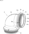
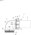
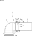
- connection mechanism for a steel pipe and a joint of the present invention mainly uses a joint 2 shown in Fig. 1 , a nut 3 shown in Fig. 2 , and an elastic ring 5 shown in Figs. 3 to 5 , thereby to construct, a steel pipe 4 by a mechanism shown in Figs. 6 to 9 , the connection mechanism for the steel pipe and the joint.
- the joint 2 has, in the end portion of a coupling cylindrical portion 2b having a fluid passage 2a inside, a connecting cylindrical portion 21 with a male thread 2c formed on the outer circumference.
- a coupling cylindrical portion 2b of the joint 2 an elbow provided with the connecting cylindrical portions 21 in both end portions of an L-shape is shown; according to the construction site, however, the coupling cylindrical portion 2b is selected from among structural shapes such as T, cross, and reducer.
- the joint 2 has a flange portion 22 protruding outward from the outer circumference near a boundary between the coupling cylindrical portion 2b and the connecting cylindrical portion 21. This flange portion 22 is provided with a partially-cut hook portion 22a, which may be, however, provided in another site.
- a flat outer circumferential surface 21a having a flat surface without forming the male thread 2c is provided around the outer circumference near the boundary between the coupling cylindrical portion 2b and the connecting cylindrical portion 21, and a flat insertion surface 21b without forming the male thread 2c is also provided at the tip.
- the inner circumference of the connecting cylindrical portion 21 near the boundary with the coupling cylindrical portion 2b is provided with a medium-large-diameter portion 21c which is larger than the diameter of the fluid passage 2a and into which the tip of a steel pipe 4 is inserted, and a large-diameter portion 21d, which houses a packing 6, is provided on the tip side of this medium-large-diameter portion 21c.
- the packing 6 is housed in the area surrounded by the inner circumferential surface of this large-diameter portion 21d and a step surface 21e created by the diameter difference between the medium-large-diameter portion 21c and the large-diameter portion 21d. Further, there is provided a corner portion 21f where the step surface 21e intersects with the medium-large-diameter portion 21c.
- the nut 3 also called a bag nut, has an annular outer cylindrical portion 31 with a female thread 3a, which is screwed with the male thread 2c formed on the outer circumference of the connecting cylindrical portion 21 of the joint 2, formed on the inner circumference, and a steel pipe support portion 32 which is provided on one end side of the annular outer cylindrical portion 31 and which supports the steel pipe 4 communicating with the fluid passage 2a.
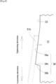
- a narrow annular side face 33 which is a face facing the joint 2 side at the time of connecting, there are circumferentially formed arc-shaped ratchet tooth 34. As shown in Figs.
- the ratchet tooth 34 forms a gentle inclined surface 34a having a gentle downward inclination angle in the direction of the relative rotation for tightening the nut 3 to the joint 2, a steep inclined surface 34b having a steep upward inclination angle in the direction of the relative rotation for loosening the nut 3 to the joint 2, and a ridge portion 34c which has the height from an annular side face 33 common to the above gentle inclined surface 34a and steep inclined surface 34b.
- the number of arc-shaped ratchet teeth 34 provided on the annular side face 33 around the entire circumference can be one or more, but as shown in Fig.
- the outer circumferential surface of the annular outer cylindrical portion 31 is provided with a plurality of non-slip bases 31a at equal spacings in the central axis direction of the nut 3, making it possible to easily rotate the nut 3 with a fingertip, providing reinforcement strength to the annular outer cylindrical portion 31.
- an insertion hole 32a to insert the steel pipe 4 is provided in the center portion of the steel pipe support portion 32 provided at the one end side of the annular outer cylindrical portion 31; inside this insertion hole 32a, there are formed a press inclined surface 32b that presses the inclined surface 41b of a mountain-shaped projection portion 41 of the steel pipe toward the joint 2 direction so as to press the inserted steel pipe 4 toward the joint 2 direction, and a vertical inner surface 32c which vertically rises from the press inclined surface 32b toward the female thread 3a.
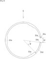
- a plate-like member is formed by cutting out or the like into a circular ring so that the elastic ring is made of an elastic metal material such as a stainless steel and has a thickness that is the same or substantially the same width as the annular side face 33; and the above elastic ring 5 has a notch portion 51 as a partial cutout of the ring.
- the length of the notch width of the notch portion 51 is not particularly limited; it may be such that the notch portion 51 is simply cut so that the distance between ring parts of one end portion 51a and another end portion 51b of the notch portion 51 is substantially zero and facing surfaces are close to each other; conversely, as shown in Fig.
- the notch portion 51 may be large until the ring length portion of the elastic ring 5 is extremely short with the one end portion 51a and other end portion 51b of the notch portion 51 close to each other having almost no distance.
- the inner diameter of the ring is substantially the same as the diameter of the male thread 2c or the diameter of the flat outer circumferential surface 21a which are formed on the outer circumference of the connecting cylindrical portion 21 of the joint 2. Even when a slight error should be caused, the elasticity allows the elastic ring 5 to fit to the connecting cylindrical portion 21.
- the elastic ring 5 is usable; in this case, the curvature radius of the inner circumference of a part of the ring that is short should be the same as the curvature radius of the curve of the outer circumference of the connecting cylindrical portion 21. Further, the outer diameter of the ring being made to be substantially the same as the outer diameter of the annular outer cylindrical portion 31 prevents the outer circumference of the elastic ring 5 from protruding from the annular outer cylindrical portion 31, improving the appearance.
- the engaging portion 51c includes a downward protrusion; thus, the engaging portion 51c proper for that site is provided in the one end portion 51a.
- This engaging portion 51c or the one end portion 51a may be preliminarily fixed to the joint 2 by welding or the like.
- the other end portion 51b of the elastic ring 5 slides on the annular side face 33 and on the gentle inclined surface 34a of the ratchet tooth 34, and abuts on the steep inclined surface 34b beyond the ridge portion 34c; thus, no special machining is required for the other end portion 51b and a cross section of cutting the ring may appear.
- the site from the other end portion 51b to the area of the center angle ⁇ of the ring is made into an inclined tip portion 51d which is inclined in one direction side, relative to the other part of the ring, at an inclination angle ⁇ , as shown in Fig.
- the 51b which is also the end portion of this inclined tip portion 51d at the time of placing, is biased in the direction of the upper face of the annular side face 33 and the upper face of the ratchet teeth 34 provided on the annular side face 33, making it easier to slide and to engage the steep inclined surface 34b as well.
- the reason why the plurality of circumferential protruding portions 51e are provided on the inner circumferential side is that, for externally fitting the ring part of the elastic ring 5 to the connecting cylindrical portion 21, the circumferential protruding portions 51e abut on the flat outer circumferential surface 21a of the connecting cylindrical portion 21, thereby to make it easy to match the height positions of the ring side face of the elastic ring 5 and the annular side face 33 for tight fitting.
- the steel pipe 4 used in the present embodiment is a long, thin-walled stainless steel pipe having two inclined surfaces, the one inclined surface 41a on the end portion 4a side of the steel pipe 4 and the other inclined surface 41b, as well shown in Figs. 10 and 11 .
- the known method and device can be used for forming the mountain-shaped protruding portion 41 on the steel pipe 4 but not limited thereto; to give an example, the pipe expanding device shown in Patent No. 346754 can be effectively used.
- any type of connecting the pipe 4 to the joint 2 by screwing the joint 2 and the nut 3 facing each other is allowed.
- the elastic ring 5 is externally fitted to the connecting cylindrical portion 21.
- the elastic ring 5 should be kept externally fitted to the innermost flat outer circumferential surface 21a.
- the present embodiment shows the example in which the engaging portion 51c provided on the one end portion 51a of the notch portion 51 is engaged with the hook portion 22a provided in the joint 2, but the position and shape of the hook portion 22a provided in the joint 2 may be another position in the joint 2 or the hooking method may be a different one.
- the end portion 51b As rotation of the nut 3 in the tightening direction progresses, the end portion 51b, while sliding on the annular side face 33 and the arcuate ratchet teeth 34, rotates in the tightening direction, as shown in Fig. 8 .
- the end portion 51b moves up the gentle inclined surface 34a of the ratchet teeth 34 and moves over the ridge portion 34c, and then steeply drops down the steep inclined surface 34b.
- the end portion 51b stops in some position on the gentle inclined surface 34a or on the annular side face 33, as shown in Fig. 6 .
- the flat insertion surface 21b at the tip of the above connecting cylindrical portion 21 advances to the inner portion of the annular outer cylindrical portion 31 and the tip face abuts on the vertical inner surface 32c of the steel pipe support portion 32.
- the other inclined surface 41b of the mountain-shaped projection portion 41 of the steel pipe 4 is pressed toward the joint 2 by the press inclined surface 32b, and the one inclined surface 41a is pressed toward the nut 3 by the packing 6 and the corner portion 21f; thus, while keeping the tightened state as to prevent fluid leak from the gap between the steel pipe 4 and the inner circumferential side face of joint 2, the steel pipe 4 is temporarily connected with the joint 2.
- a notch portion of the notch portion 51 of the ring of the elastic ring 5 is only as wide as the notch groove that was cut, the contour angle of the ring is nearly 360°, and when in use, the notch portion will be large enough to substantially circle once the flat outer circumferential surface 21a of the connecting cylindrical portion 21.
- the ring part of the elastic ring 5 is, substantially around the entire circumference, squeezed between the joint 2 or flange portion 22 and the annular side face 33; thus, even when a large force acts in the loosening direction, the frictional resistance is increased and the end portion 51a abuts on the steep inclined surface 34b, thus firmly performing the tightening without breaking the elastic ring 5.
- enlarging the notch portion 51 makes the contour of the ring smaller and shorter; shortening the length of the elastic ring 5, however, can save the material cost, and in addition, make plural elastic rings 5 usable for the connecting of one set of joint 2 and nut 3, providing an advantage.
- the example has been described in which the male thread is screwed with the female thread and, between the joint 2 and the nut 3, the steel pipe 4 having the mountain-shaped protruding portion 41 is placed, thereby to join the joint 2 with the nut 3, but the present embodiment is also applicable to a connection mechanism including the step of causing any one or both of the joint 2 and the nut 3 to relatively rotate in the loosening or tightening direction by a measure other than the thread coupling or by using the steel pipe 4 without the mountain-shaped protruding portion 41.
- a tool or the like is used thereby to rotate the joint 2 and the nut 3 in the loosening direction, separately from each other or simultaneously with each other, thereby to shear off the elastic ring 5 or to shear off the portion of engagement or abutment of the elastic ring 5 end portion on the joint 2 or the ratchet tooth 34, thus making it possible to easily perform disassembling.
- connection mechanism for the steel pipe and the joint of the present invention loosening can be prevented simply by keeping, at the time of connecting, the elastic ring 5 externally fitted to the connecting cylindrical portion 21, thus improving the efficiency of connecting the steel pipe 4.
- connection mechanism for the steel pipe and the joint of the present invention employs the construction in which the joint and the nut tighten and connect the steel pipe with the elastic ring 5 interposed thereby to prevent loosening; thus, the connection mechanism can be used for constructing various steel pipe nets, through which the fluid passes, thereby to expand the range of application, is expected to have a large demand, and can greatly contribute to the development of industry.
Landscapes
- Engineering & Computer Science (AREA)
- General Engineering & Computer Science (AREA)
- Mechanical Engineering (AREA)
- Joints With Pressure Members (AREA)
- Mutual Connection Of Rods And Tubes (AREA)
- Piles And Underground Anchors (AREA)
- Joints With Sleeves (AREA)
Applications Claiming Priority (2)
| Application Number | Priority Date | Filing Date | Title |
|---|---|---|---|
| JP2022105024A JP7230264B1 (ja) | 2022-06-29 | 2022-06-29 | 鋼管と継手の接続機構 |
| PCT/JP2023/022314 WO2024004694A1 (fr) | 2022-06-29 | 2023-06-15 | Mécanisme de raccordement de tuyau en acier et de joint |
Publications (2)
| Publication Number | Publication Date |
|---|---|
| EP4549794A1 true EP4549794A1 (fr) | 2025-05-07 |
| EP4549794A4 EP4549794A4 (fr) | 2026-04-08 |
Family
ID=85330634
Family Applications (1)
| Application Number | Title | Priority Date | Filing Date |
|---|---|---|---|
| EP23804885.4A Pending EP4549794A4 (fr) | 2022-06-29 | 2023-06-15 | Mécanisme de raccordement de tuyau en acier et de joint |
Country Status (5)
| Country | Link |
|---|---|
| EP (1) | EP4549794A4 (fr) |
| JP (1) | JP7230264B1 (fr) |
| CN (1) | CN117677789A (fr) |
| TW (1) | TW202409462A (fr) |
| WO (1) | WO2024004694A1 (fr) |
Families Citing this family (1)
| Publication number | Priority date | Publication date | Assignee | Title |
|---|---|---|---|---|
| JP7445339B1 (ja) * | 2023-01-30 | 2024-03-07 | オーエヌ工業株式会社 | 鋼管と継手の接続機構 |
Family Cites Families (11)
| Publication number | Priority date | Publication date | Assignee | Title |
|---|---|---|---|---|
| US2491406A (en) * | 1945-12-06 | 1949-12-13 | Aeroquip Corp | Coupling |
| GB693517A (en) * | 1950-02-17 | 1953-07-01 | Aeroquip Corp | Improvements in and relating to mechanical connecting means |
| JPS4828601Y1 (fr) * | 1970-10-20 | 1973-08-29 | ||
| JPS602006U (ja) * | 1984-05-17 | 1985-01-09 | 北 源一 | ゆるみ止め機構付管継手装置 |
| JP4852369B2 (ja) | 2006-07-18 | 2012-01-11 | 積水化学工業株式会社 | 管継手 |
| ES2488921T3 (es) | 2007-10-19 | 2014-09-01 | O.N. Industries Co. Ltd. | Mecanismo de conexión entre un tubo de acero inoxidable de pared delgada y una junta |
| JP2012102783A (ja) * | 2010-11-09 | 2012-05-31 | Yoshiro Takiguchi | 締付固定具 |
| JP2016142293A (ja) * | 2015-01-30 | 2016-08-08 | オーエヌ工業株式会社 | 薄肉ステンレス鋼管と継手の接続機構 |
| JP6653492B1 (ja) * | 2019-02-13 | 2020-02-26 | 孝一 松永 | スプリングワッシャ一体型ボルトナット |
| CN114183454A (zh) | 2021-12-17 | 2022-03-15 | 张家陶 | 一种互锁式防松螺母 |
| CN114278660B (zh) | 2022-01-04 | 2023-02-07 | 龚作钰 | 设定弹舌刚度控制拆卸的防松螺栓组件 |
-
2022
- 2022-06-29 JP JP2022105024A patent/JP7230264B1/ja active Active
-
2023
- 2023-06-15 WO PCT/JP2023/022314 patent/WO2024004694A1/fr not_active Ceased
- 2023-06-15 CN CN202380012942.9A patent/CN117677789A/zh active Pending
- 2023-06-15 EP EP23804885.4A patent/EP4549794A4/fr active Pending
- 2023-06-16 TW TW112122610A patent/TW202409462A/zh unknown
Also Published As
| Publication number | Publication date |
|---|---|
| CN117677789A (zh) | 2024-03-08 |
| EP4549794A4 (fr) | 2026-04-08 |
| WO2024004694A1 (fr) | 2024-01-04 |
| JP2024005043A (ja) | 2024-01-17 |
| JP7230264B1 (ja) | 2023-02-28 |
| TW202409462A (zh) | 2024-03-01 |
Similar Documents
| Publication | Publication Date | Title |
|---|---|---|
| KR20160005645A (ko) | 파이프 조인트 | |
| US3191975A (en) | Hose fitting | |
| JPH07269749A (ja) | 管継手装置 | |
| EP4549794A1 (fr) | Mécanisme de raccordement de tuyau en acier et de joint | |
| US20070284878A1 (en) | Sealing fitting for stainless steel tubing | |
| US20240200698A1 (en) | Pipe joint | |
| EP3726115B1 (fr) | Couplage rapide pour tuyaux et similaires | |
| JP2019509450A (ja) | ストローク抵抗特徴を備えた導管継手 | |
| EP4660502A1 (fr) | Mécanisme de raccordement pour tuyau d'acier et joint | |
| US20070013189A1 (en) | Sealing fitting for stainless steel tubing | |
| JP6684312B2 (ja) | ゆるみ防止金属製雄ねじ | |
| EP4382791A1 (fr) | Bague de pression, joint de tuyau et procédé d'assemblage de tuyaux | |
| JP7602894B2 (ja) | 管継手、押輪および管の接合方法 | |
| JP6924538B1 (ja) | 管継手構造 | |
| JP2001227680A (ja) | 外周溝付き管体 | |
| JP2023069093A (ja) | 押輪、管継手および管の接合方法 | |
| CN111480027A (zh) | 波纹管连接装置及其联接方法 | |
| JP2008019975A (ja) | ハウジング形管継手 | |
| JP2025521992A (ja) | 第2の管に接続されるように意図された改良された管アセンブリ | |
| JP6518538B2 (ja) | コア部材及び管継手 | |
| JP2023037052A (ja) | 押輪、管継手および管の接合方法 | |
| JP5690553B2 (ja) | 樹脂管継手の組付構造及び樹脂管継手の組付方法 | |
| WO2006032840A1 (fr) | Raccord pour extremite de tuyau et son procede d’assemblage |
Legal Events
| Date | Code | Title | Description |
|---|---|---|---|
| STAA | Information on the status of an ep patent application or granted ep patent |
Free format text: STATUS: UNKNOWN |
|
| STAA | Information on the status of an ep patent application or granted ep patent |
Free format text: STATUS: THE INTERNATIONAL PUBLICATION HAS BEEN MADE |
|
| PUAI | Public reference made under article 153(3) epc to a published international application that has entered the european phase |
Free format text: ORIGINAL CODE: 0009012 |
|
| STAA | Information on the status of an ep patent application or granted ep patent |
Free format text: STATUS: REQUEST FOR EXAMINATION WAS MADE |
|
| 17P | Request for examination filed |
Effective date: 20231123 |
|
| AK | Designated contracting states |
Kind code of ref document: A1 Designated state(s): AL AT BE BG CH CY CZ DE DK EE ES FI FR GB GR HR HU IE IS IT LI LT LU LV MC ME MK MT NL NO PL PT RO RS SE SI SK SM TR |
|
| DAV | Request for validation of the european patent (deleted) | ||
| DAX | Request for extension of the european patent (deleted) | ||
| A4 | Supplementary search report drawn up and despatched |
Effective date: 20260305 |
|
| RIC1 | Information provided on ipc code assigned before grant |
Ipc: F16L 19/028 20060101AFI20260227BHEP Ipc: F16B 37/00 20060101ALI20260227BHEP Ipc: F16B 39/282 20060101ALI20260227BHEP Ipc: F16L 19/00 20060101ALI20260227BHEP Ipc: F16L 19/02 20060101ALI20260227BHEP Ipc: F16L 19/025 20060101ALI20260227BHEP Ipc: F16B 39/10 20060101ALI20260227BHEP |