EP4549820A1 - Appareil de cuisson à chauffage - Google Patents
Appareil de cuisson à chauffage Download PDFInfo
- Publication number
- EP4549820A1 EP4549820A1 EP24209283.1A EP24209283A EP4549820A1 EP 4549820 A1 EP4549820 A1 EP 4549820A1 EP 24209283 A EP24209283 A EP 24209283A EP 4549820 A1 EP4549820 A1 EP 4549820A1
- Authority
- EP
- European Patent Office
- Prior art keywords
- air
- heating
- board
- blow
- cooking compartment
- Prior art date
- Legal status (The legal status is an assumption and is not a legal conclusion. Google has not performed a legal analysis and makes no representation as to the accuracy of the status listed.)
- Pending
Links
Images


Classifications
-
- F—MECHANICAL ENGINEERING; LIGHTING; HEATING; WEAPONS; BLASTING
- F24—HEATING; RANGES; VENTILATING
- F24C—DOMESTIC STOVES OR RANGES ; DETAILS OF DOMESTIC STOVES OR RANGES, OF GENERAL APPLICATION
- F24C15/00—Details
- F24C15/006—Arrangements for circulation of cooling air
-
- F—MECHANICAL ENGINEERING; LIGHTING; HEATING; WEAPONS; BLASTING
- F24—HEATING; RANGES; VENTILATING
- F24C—DOMESTIC STOVES OR RANGES ; DETAILS OF DOMESTIC STOVES OR RANGES, OF GENERAL APPLICATION
- F24C7/00—Stoves or ranges heated by electric energy
- F24C7/08—Arrangement or mounting of control or safety devices
- F24C7/082—Arrangement or mounting of control or safety devices on ranges, e.g. control panels, illumination
- F24C7/085—Arrangement or mounting of control or safety devices on ranges, e.g. control panels, illumination on baking ovens
-
- H—ELECTRICITY
- H05—ELECTRIC TECHNIQUES NOT OTHERWISE PROVIDED FOR
- H05B—ELECTRIC HEATING; ELECTRIC LIGHT SOURCES NOT OTHERWISE PROVIDED FOR; CIRCUIT ARRANGEMENTS FOR ELECTRIC LIGHT SOURCES, IN GENERAL
- H05B6/00—Heating by electric, magnetic or electromagnetic fields
- H05B6/64—Heating using microwaves
- H05B6/642—Cooling of the microwave components and related air circulation systems
Definitions
- the present disclosure relates to a heating cooker.
- a heating cooker of JP 2000-346371 A includes an inverter circuit board and a cooling fan.
- a front or back surface of the inverter circuit board is disposed in an air passage on an upstream side from the cooling fan, and the other surface is disposed in the air passage on a downstream side.
- the heating cooker disclosed in JP 2000-346371 A uniformly cools both the front and back surfaces of the inverter circuit board, and is not configured to effectively cool a specific portion of the inverter circuit board.
- an object of the present disclosure is to provide a heating cooker capable of effectively cooling a specific portion of an inverter circuit board.
- a heating cooker includes a heating cooking compartment, a housing, a circuit board, an air blower, and a division partition.
- the heating cooking compartment accommodates a heating-target object.
- the housing accommodates the heating cooking compartment.
- the circuit board is disposed between the housing and the heating cooking compartment.
- the air blower has a first blow-out port accommodating a first blast fan and blowing out air toward the circuit board, and the air blower forms a first blast fan air flow with air blown out from the first blow-out port.
- the division partition divides a flow channel through which the first blast fan air flow flows from the first blow-out port toward the circuit board.
- the division partition includes a board case configured to accommodate the circuit board.
- the board case includes a bottom wall portion functioning as a partition between the heating cooking compartment and the circuit board.
- the circuit board is disposed apart from the bottom wall portion.
- the first blow-out port is disposed at a position spanning between a surface on one side and a surface on the other side of the circuit board.
- the board case includes, on the bottom wall portion, a flow restricting portion restricting a flow quantity of air flowing in the board case.
- the heating cooker is capable of effectively cooling a specific portion of an inverter circuit board.
- FIG. 1 is a perspective view illustrating the heating cooker 100.
- FIG. 1 illustrates the external appearance of the heating cooker 100 when viewed diagonally from the upper right front.
- the heating cooker 100 heats and cooks a heating-target object.
- the heating-target object is, for example, a food item.
- the heating cooker 100 includes a housing 10, a door 20, and an operation panel 30.
- the operation panel 30 is a substantially rectangular plate-shaped member.
- the operation panel 30 receives an operation from a user.
- the operation includes, for example, a cooking method for heating and cooking a heating-target object.
- the operation panel 30 includes a display unit.
- the display unit displays various items of information.
- the display unit includes a liquid crystal panel.
- a side of the heating cooker 100 on which the operation panel 30 is disposed is defined as a front side of the heating cooker 100, and a side (back surface side) opposite to the front side is defined as a rear side of the heating cooker 100.
- a right side is defined as a right side of the heating cooker 100, and a side opposite to the right side is defined as a left side of the heating cooker 100.
- a side on which the operation panel 30 is disposed is defined as an upper side of the heating cooker 100, and a side (bottom side) opposite to the upper side is defined as a lower side of the heating cooker 100.
- these directions and sides are not intended to limit directions and sides when the heating cooker 100 of the present disclosure is used.
- a first direction D1 is an upward direction.
- a second direction D2 is a forward direction.
- a third direction D3 is a left direction.
- the housing 10 is a box-shaped member. Specifically, the housing 10 has a right outer wall 11, a left outer wall 12, an upper outer wall 13, a lower outer wall 14, a rear outer wall 15, and a front wall 60 to be described below.
- the rear outer wall 15 intersects the second direction D2.
- the right outer wall 11 and the left outer wall 12 face each other in the third direction D3.
- the upper outer wall 13 and the lower outer wall 14 face each other in the first direction D1.
- the housing 10 accommodates the heating cooking compartment 50 to be described below.
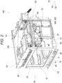
- FIGS. 2 and 3 are perspective views illustrating the heating cooker 100 in a state where the housing 10 except for the front wall 60 thereof is removed.
- FIG. 2 illustrates the external appearance of the heating cooker 100 when viewed diagonally from the upper right front.
- FIG. 3 illustrates the external appearance of the heating cooker 100 when viewed diagonally from the lower right front.
- the heating cooker 100 further includes the heating cooking compartment 50 and a placement portion 70.
- the heating cooking compartment 50 allows a heating-target object to be accommodated therein.
- the heating cooking compartment 50 is accommodated in the housing 10.
- the heating cooking compartment 50 has, for example, a substantially rectangular parallelepiped shape.
- the heating cooking compartment 50 has a right wall 51, a left wall 52, an upper wall 53, a lower wall 54, and a rear wall 55.
- the rear wall 55 intersects the second direction D2.
- the right wall 51 and the left wall 52 face each other in the third direction D3.
- the upper wall 53 and the lower wall 54 face each other in the first direction D1.
- the placement portion 70 is a dish-shaped member.
- the placement portion 70 is accommodated in the heating cooking compartment 50.
- the placement portion 70 is configured to allow the heating-target object to be placed.
- the placement portion 70 includes a table 71 and a drive motor 72.
- the placement portion 70 is rotatable about a rotation axis in the first direction D1.
- the heating-target object is placed on the table 71.
- the table 71 is disposed at the center of the lower wall 54.
- the drive motor 72 rotates the table 71. To be specific, the drive motor 72 rotates the table 71 about a rotation axis in the first direction D1. The drive motor 72 is disposed below the heating cooking compartment 50.
- the heating cooker 100 further includes a first space R1, a second space R2, a third space R3, a fourth space R4, and a fifth space R5.
- the first space R1 is disposed between the upper outer wall 13 and the upper wall 53.
- the second space R2 is disposed between the lower outer wall 14 and the lower wall 54.
- the third space R3 is disposed between the rear outer wall 15 and the rear wall 55.
- the fourth space R4 is disposed between the right outer wall 11 and the right wall 51.
- the fifth space R5 is disposed between the left outer wall 12 and the left wall 52.
- the front wall 60 is a plate-shaped member having a quadrangular shape.
- the front wall 60 faces the rear wall 55.
- the front wall 60 faces the rear outer wall 15.
- the front wall 60 has an opening 61 and suction ports 62.
- the opening 61 allows an inside and an outside of the heating cooking compartment 50 to communicate with each other.
- the suction ports 62 suction air from the outside of the heating cooker 100. That is, the housing 10 has the suction ports 62 through which air is suctioned from the outside of the heating cooker 100. In other words, the housing 10 has the front wall 60 in which the suction ports 62 are formed.
- the right wall 51 and the left wall 52 face each other with the upper wall 53 and the lower wall 54 interposed therebetween.
- the rear wall 55 faces the opening 61.
- a plurality of suction ports 62 are disposed above the opening 61. Each of the plurality of suction ports 62 allows an inside and an outside of the first space R1 to communicate with each other.
- the plurality of suction ports 62 form eight columns. In each of the eight columns of the suction ports 62, three suction ports 62 are arranged in a column in an up-down direction.
- FIG. 4 is a perspective view illustrating the door 20.
- the door 20 opens and closes the opening 61.
- the door 20 includes a substantially rectangular plate-shaped member 21 and a rotary shaft unit 22.
- the rotary shaft unit 22 is positioned below the plate-shaped member 21.
- the plate-shaped member 21 opens and closes the opening 61. Specifically, the plate-shaped member 21 rotates about a rotation axis in the third direction D3.
- the plate-shaped member 21 opens the opening 61 in a state of being orthogonal to the first direction D1.
- the plate-shaped member 21 closes the opening 61 in a state of being orthogonal to the second direction D2.
- the door 20 includes a first connection member 23 and a second connection member 24. Both the first connection member 23 and the second connection member 24 connect the heating cooking compartment 50 and the door 20 when the door 20 is positioned at a closed position.
- the first connection member 23 and the second connection member 24 are attached to the plate-shaped member 21.
- the first connection member 23 and the second connection member 24 face each other in the left-right direction.
- the first connection member 23 is attached to a left edge portion of a rear surface of the plate-shaped member 21.
- the second connection member 24 is attached to a right edge portion of the rear surface of the plate-shaped member 21.
- each of the first connection member 23 and the second connection member 24 has a hook member.
- the hook member is a plate-shaped member having a longitudinal direction thereof in the front-rear direction.
- the hook member includes a claw portion and a rotation pin portion.
- the rotation pin portion is positioned at one end portion of the hook member.
- the rotation pin portion rotates about a rotation axis extending in the third direction D3.
- the claw portion has a projecting portion projecting downward.
- the claw portion is positioned at the other end portion of the hook member.
- the claw portion is rotatable around the rotation pin portion.
- the claw portion can engage with a hole formed in the front wall 60.
- FIG. 5 is a view illustrating a schematic cross section of the heating cooker 100.
- FIG. 5 is a cross-sectional view illustrating the heating cooker 100 cut along a plane orthogonal to the third direction D3.
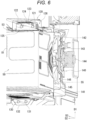
- FIG. 6 is a view illustrating a schematic cross section of an air blower 140 according to the embodiment.
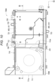
- FIG. 7 is a perspective view illustrating the heating cooker 100 in a state where the housing 10 except for the front wall 60 thereof is removed. To be specific, FIG. 7 illustrates the external appearance of the heating cooker 100 when viewed diagonally from the upper left rear.
- the heating cooker 100 further includes a discharge unit 40.
- the discharge unit 40 partitions between an inside and an outside of the second space R2.
- the discharge unit 40 is a plate-shaped member having a crank cross sectional shape.
- a lower portion of the discharge unit 40 is bent toward the front side.
- a length of the discharge unit 40 in the left-right direction is set to be substantially the same as a length of the lower wall 54 in the left-right direction.
- a front end of the discharge unit 40 is positioned behind a front end of the door 20.
- the discharge unit 40 is disposed below the opening 61. An upper portion of the discharge unit 40 is fixed to a lower surface of the lower wall 54. As illustrated in FIGS. 2 and 3 , the discharge unit 40 forms discharge ports 41 in cooperation with the front wall 60.
- the heating cooker 100 includes a microwave supply unit 110, a first heater unit 120, a second heater unit 130, and the air blower 140.
- Each of the microwave supply unit 110, the first heater unit 120, the second heater unit 130, and the air blower 140 heats the heating-target object.
- the microwave supply unit 110 supplies microwaves into the heating cooking compartment 50.
- the microwave supply unit 110 is disposed on the upper wall 53 of the heating cooking compartment 50. Specifically, the microwave supply unit 110 is positioned above the heating cooking compartment 50 with the upper wall 53 interposed therebetween. As illustrated in FIGS. 3 and 7 , the microwave supply unit 110 includes a partition member 111, a radiation chamber, a magnetron 113, and a waveguide 114.
- the magnetron 113 is disposed closer to the front wall 60 than the first heater unit 120.
- the magnetron 113 generates microwaves.
- the waveguide 114 propagates microwaves generated by the magnetron 113 to the radiation chamber.
- the partition member 111 is disposed between the radiation chamber and the upper wall 53 of the heating cooking compartment 50.
- a material of the partition member 111 are non-metals, and include a ceramic or mica.
- the partition member 111 transmits microwaves.
- materials of the radiation chamber and the waveguide 114 include metals.
- the first heater unit 120 As illustrated in FIGS. 5 and 6 , the first heater unit 120 is disposed above the heating cooking compartment 50. Specifically, the first heater unit 120 is disposed on the upper wall 53 of the heating cooking compartment 50.
- the first heater unit 120 includes a first heater 121, a thermal shield plate 122, a first tube 123, a heat reflection plate 124, and a glass plate 125.
- the first heater 121 is, for example, a carbon heater.
- the first heater 121 in the state of power application generates heat. As a result, since the temperature rises quickly, the heating-target object can be cooked in a short time.
- the thermal shield plate 122 shields heat.
- the thermal shield plate 122 covers an upper side, a front side, and a rear side of the first heater 121.
- the thermal shield plate 122 is made of a material including metal.
- the first tube 123 is made of glass.
- the first tube 123 accommodates the first heater 121.
- the first tube 123 extends in the third direction D3.
- the heat reflection plate 124 covers an upper side, a front side, and a rear side of the first heater 121.
- the heat reflection plate 124 reflects heat toward the heating cooking compartment 50.
- An air layer 126 is provided between the heat reflection plate 124 and the thermal shield plate 122.
- the glass plate 125 is a substantially rectangular plate-shaped member.
- the glass plate 125 is disposed between a lower side of the first tube 123 and the heating cooking compartment 50.
- the glass plate 125 separates the first tube 123 from the heating cooking compartment 50.
- the glass plate 125 transmits heat rays from the first heater 121 to the heating cooking compartment 50.
- the glass plate 125 prevents moisture and salt from moving from the heating cooking compartment 50 to the first tube 123. Accordingly, a devitrification phenomenon of the first tube 123 can be prevented.
- the second heater unit 130 is disposed on the lower wall 54 of the heating cooking compartment 50.
- the second heater unit 130 includes a second heater 131 and a second heater case 132.
- the second heater 131 is, for example, a nichrome wire.
- the second heater 131 in the state of power application generates heat.
- An output of the second heater 131 is lower than an output of the first heater 121.
- the second heater case 132 covers a lower side, a front side, and a rear side of the second heater 131.
- the second heater case 132 is made of a material including metal.
- the second heater 131 in the state of power application generates heat.
- the air blower 140 is configured to supply hot air into the heating cooking compartment 50.
- the air blower 140 is disposed in the third space R3. Specifically, the air blower 140 is positioned behind the heating cooking compartment 50 with the rear wall 55 interposed therebetween.
- the air blower 140 includes an air blowing chamber 141, a third heater 142, a centrifugal fan 143, a drive unit 144, a partition member 145, and a heat shield plate 146.
- the air blowing chamber 141 is, for example, a box-shaped member made of metal.
- the centrifugal fan 143 has a plurality of blades.
- the third heater 142 and the centrifugal fan 143 are accommodated in the air blowing chamber 141.
- the third heater 142 heats air inside the air blowing chamber 141 to generate hot air.
- the third heater 142 has an annular shape when viewed from the front side toward the rear side.
- the third heater 142 is disposed along an outer circumference of the centrifugal fan 143.
- the rear wall 55 has a suction hole portion and a blow-out hole portion.
- the suction hole portion is, for example, a group of a plurality of punched holes.
- the blow-out hole portion is also, for example, a group of a plurality of punched holes.
- a punched hole has, for example, a circular shape.
- a diameter of a punched hole of each of the suction hole portion and the blow-out hole portion is, for example, 3 mm or larger and 4 mm or smaller in order to prevent microwaves from leaking from the inside of the heating cooking compartment 50. The diameter is preferably 3.4 mm.
- the partition member 145 is, for example, a plate-shaped member made of metal.
- the partition member 145 has, for example, an oblong shape when viewed from the front side toward the rear side.
- the partition member 145 is disposed on substantially the entire surface of the rear wall 55. Specifically, the partition member 145 is positioned on the outward side from the rear wall 55.
- the heat shield plate 146 is, for example, a plate-shaped member made of metal.
- the heat shield plate 146 is, for example, a plate-shaped member having a quadrangular shape when viewed from the front side toward the rear side.
- the heat shield plate 146 is positioned on the outward side from the partition member 145.
- the drive unit 144 is positioned an outward side from the air blowing chamber 141. Specifically, the drive unit 144 is positioned on an outward side from the heat shield plate 146, and a shaft portion of the drive unit 144 penetrates the partition member 145 and the heat shield plate 146 and is connected to the centrifugal fan 143. The drive unit 144 drives the centrifugal fan 143.
- the drive unit 144 includes, for example, a motor.
- the drive unit 144 is disposed between the housing 10 and the heating cooking compartment 50.
- the air blower 140 draws in hot air inside the heating cooking compartment 50 through the suction hole portion, and blows hot air into the heating cooking compartment 50 through the blow-out hole portion.
- the air blower 140 draws in hot air from a central portion inside the heating cooking compartment 50 and blows the hot air to a peripheral border portion inside the heating cooking compartment 50.
- the entire inside of the heating cooking compartment 50 can be heated by driving the air blower 140.
- the heating cooking compartment 50 further includes an intake hole portion 81, an exhaust hole portion 82, an intake damper unit 83, and an exhaust damper unit 84.
- the intake hole portion 81 allows the inside and the outside of the heating cooking compartment 50 to communicate with each other.
- the intake hole portion 81 is disposed on the left wall 52.
- the intake hole portion 81 has, for example, a quadrangular shape.
- the intake hole portion 81 includes, for example, a plurality of punched holes.
- a punched hole has, for example, a circular shape.
- a diameter of a punched hole of the intake hole portion 81 is, for example, 3 mm or larger and 4 mm or smaller in order to prevent microwaves from leaking. The diameter is preferably 3.4 mm.
- the intake damper unit 83 opens and closes the intake hole portion 81.
- the intake damper unit 83 is attached to an outer side of the left wall 52.
- the intake damper unit 83 opens the intake hole portion 81, the inside and the outside of the heating cooking compartment 50 communicate with each other. As a result, air is guided to the intake hole portion 81.
- the intake damper unit 83 closes the intake hole portion 81, the inside and the outside of the heating cooking compartment 50 do not communicate with each other. As a result, air is not guided to the intake hole portion 81.
- the exhaust hole portion 82 allows the inside and the outside of the heating cooking compartment 50 to communicate with each other.
- the exhaust hole portion 82 is disposed on the right wall 51.
- the exhaust hole portion 82 has, for example, a quadrangular shape.
- the exhaust hole portion 82 includes, for example, a plurality of punched holes.
- a punched hole has, for example, a circular shape.
- a diameter of a punched hole of the exhaust hole portion 82 is, for example, 3 mm or larger and 4 mm or smaller in order to prevent microwaves from leaking. The diameter is preferably 3.4 mm.
- the exhaust damper unit 84 opens and closes the exhaust hole portion 82.
- the exhaust damper unit 84 is attached to an outer side of the right wall 51.
- the exhaust damper unit 84 opens the exhaust hole portion 82, the inside and the outside of the heating cooking compartment 50 communicate with each other.
- the exhaust damper unit 84 closes the exhaust hole portion 82, the inside and the outside of the heating cooking compartment 50 do not communicate with each other.
- the intake damper unit 83 opens the intake hole portion 81
- the exhaust damper unit 84 opens the exhaust hole portion 82.
- air is guided to the intake hole portion 81.
- the air is blown into the heating cooking compartment 50 through the intake hole portion 81.
- the air blown from the intake hole portion 81 moves into the heating cooking compartment 50 in a direction opposite to the third direction D3.
- the air is discharged from the exhaust hole portion 82 to the outside of the heating cooking compartment 50.
- the air performs scavenging of steam or the like in the heating cooking compartment 50.
- FIG. 8 is a plan view illustrating the heating cooker 100 in a state where the housing 10 except for the front wall 60 thereof is removed according to the embodiment.
- the heating cooker 100 includes a first fan 200, a first wind direction plate 500, a first guide unit 550, and a second wind direction plate 600.
- the first fan 200 generates an air flow. As illustrated in FIGS. 2 , 5 , and 7 , the first fan 200 generates a first air flow AF, a second air flow BF, a third air flow CF, a fourth air flow DF, and a fifth air flow EF.
- the second air flow BF, the third air flow CF, the fourth air flow DF, and the fifth air flow EF are branches from the first air flow AF.
- the first fan 200 corresponds to, for example, a "second blast fan".
- the first air flow AF mainly cools the drive motor 72, the second heater unit 130, and the drive unit 144.
- the second air flow BF mainly cools the first heater unit 120.
- the third air flow CF mainly performs scavenging of the inside of the heating cooking compartment 50.
- the fourth air flow DF mainly cools a motor of the intake damper unit 83.
- the fifth air flow EF mainly cools a motor of the exhaust damper unit 84.
- the first air flow AF (the first air flow AF1) corresponds to, for example, a "second blast fan air flow".
- the first fan 200 is a Sirocco fan. As illustrated in FIGS. 7 and 8 , the first fan 200 is disposed between the rear wall 55 of the heating cooking compartment 50 and the rear outer wall 15 of the housing 10. Specifically, the first fan 200 is disposed in the region in which the first space R1 and the third space R3 overlap each other. The first fan 200 is disposed between the heating cooking compartment 50 and the housing 10, and suctions air from the suction ports 62 to a space between the heating cooking compartment 50 and the housing 10.
- the first fan 200 includes a left fan portion 210 and a right fan portion 220.
- the left fan portion 210 supplies cooling air to a left region of the first fan 200 to generate the left-side first air flow AF1 that is a part of the first air flow AF.
- the left fan portion 210 is positioned at the same height as the plurality of suction ports 62.
- the left fan portion 210 generates a negative pressure having a pressure lower than an external normal pressure on an upstream side of the left fan portion 210 in order to draw air.
- the left fan portion 210 takes air outside the heating cooker 100 into the first space R1 and generates the left-side first air flow AF1 between the upper wall 53 of the heating cooking compartment 50 and the upper outer wall 13 of the housing 10.
- the first wind direction plate 500 includes a first skew plate 501, a second skew plate 503, and a horizontal plate 502.
- the first skew plate 501 guides the third air flow CF to the suction port 501a of the intake damper unit 83.
- the third air flow CF is a part of the left-side first air flow AF2 flowing along the first skew plate 501.
- the first skew plate 501 guides the fourth air flow DF to the suction port 501b directed to the left wall 52.
- the fourth air flow DF is the remaining part of the left-side first air flow AF2 flowing along the first skew plate 501.
- the first skew plate 501 is disposed on the heat shield plate 146.
- the first skew plate 501 is provided upright on the heat shield plate 146.
- the first skew plate 501 extends from below the left fan portion 210 toward the left wall 52.
- the second skew plate 503 guides the second air flow BF to the suction port 503a of the first heater unit 120.
- the second air flow BF is a part of the left-side first air flow AF2 flowing along the second skew plate 503.
- the second skew plate 503 guides the fourth air flow DF to the suction port 501b directed to the left wall 52.
- the fourth air flow DF is the remaining part of the left-side first air flow AF2 flowing along the second skew plate 503. That is, the fourth air flow DF includes the remaining part of the left-side first air flow AF2 flowing along the first skew plate 501 and the remaining part of the left-side first air flow AF2 flowing along the second skew plate 503.
- the second skew plate 503 is disposed on the heat shield plate 146.
- the second skew plate 503 is provided upright on the heat shield plate 146.
- the second skew plate 503 is positioned on the upper side from the first skew plate 501.
- the second skew plate 503 extends from below the left fan portion 210 toward the left wall 52.
- the horizontal plate 502 is disposed on the left wall 52.
- the horizontal plate 502 is provided upright on the left wall 52.
- the horizontal plate 502 passes below the intake damper unit 83 from the rear wall 55 and extends toward the front wall 60.
- the first guide unit 550 guides the second air flow BF from the left fan portion 210 to the first heater unit 120.
- the first guide unit 550 is a cylindrical body.
- the cylindrical body has the suction port 503a and a blow-out port.
- the cylindrical body is disposed on the left wall 52.
- the suction port 503a is open in the direction opposite to the second direction D2.
- the blow-out port is open toward the first heater unit 120 and the intake hole portion 81.
- the second wind direction plate 600 includes a skew plate 601 and a horizontal plate 602.
- the skew plate 601 guides the fifth air flow EF to the exhaust damper unit 84.
- the fifth air flow EF is a part of the right-side first air flow AF2.
- the skew plate 601 is disposed on the heat shield plate 146.
- the skew plate 601 is provided upright on the heat shield plate 146.
- the skew plate 601 extends from below the right fan portion 220 toward the right wall 51.
- the horizontal plate 602 is disposed on the right wall 51.
- the horizontal plate 602 is provided upright on the right wall 51.
- the horizontal plate 602 passes below the exhaust damper unit 84 from the rear wall 55 and extends toward the front wall 60.
- FIG. 9 is a perspective view illustrating an inverter unit 700A according to the embodiment. To be specific, FIG. 9 illustrates the external appearance of the inverter unit 700A when viewed from a lower rear side in which an upper half portion of the division partition 700 is omitted.
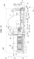
- FIG. 10 is a plan view illustrating the inverter unit 700A according to the embodiment. To be specific, FIG. 10 illustrates the external appearance of the inverter unit 700A when viewed from below in which the upper half portion of the division partition 700 is omitted.
- FIG. 11 is a cross-sectional view along line XI-XI in FIG. 10 .
- the second fan 240 forms a sixth air flow FF by air blown out from the fan blow-out port 241.
- the sixth air flow FF corresponds to, for example, a "first blast fan air flow”.
- the inverter power supply 400 changes a frequency and a magnitude of voltage. As illustrated in FIGS. 5 and 9 to 11 , the inverter power supply 400 is disposed behind the second fan 240. As illustrated in FIGS. 5 and 8 , the inverter power supply 400 is disposed in the first flow channel F1.
- the inverter power supply 400 includes electric components E and a board 410.
- the inverter power supply 400 has a first end portion 401 on a side close to the suction ports 62 and a second end portion 402 on a side far from the suction ports 62.
- the board 410 corresponds to, for example, a "circuit board".
- Examples of the electric components E include a rectifier circuit that rectifies power obtained from a commercial power source, a control circuit, a semiconductor switching element that transmits output power of the rectifier circuit to a resonance circuit via a filter circuit in response to an output signal of the control circuit, a step-up transformer that steps up and outputs resonance power of the resonance circuit, and a high-voltage rectifier circuit (all not illustrated).
- the board 410 supports the electric components E. As illustrated in FIG. 11 , the board 410 is disposed to be orthogonal to the first direction D1. The board 410 is disposed between the housing 10 and the heating cooking compartment 50. In the board 410, a plurality of electric components E are mounted on a surface 410a on the first direction D1 side. A surface 410b of the board 410 on the opposite side of the first direction D1 is mainly a solder surface.
- the division partition 700 divides a flow channel through which an air flow flows.
- the division partition 700 is made of, for example, a synthetic resin.
- a second flow channel F2 in which the sixth air flow FF flows from the fan blow-out port 241 of the second fan 240 toward the board 410 (the inverter power supply 400) is divided from the first flow channel F1.
- cooling performance for the cooling target portion disposed upstream of the cooling fan can be enhanced.
- the division partition 700 is provided to divide the first flow channel F1 to form the second flow channel F2 in which the sixth air flow FF blown out from the fan blow-out port 241 of the second fan 240 toward the board 410 flows, it is possible to reduce suction of air from between the fan blow-out port 241 of the second fan 240 and the board 410, and it is possible to secure a volume of cooling air flowing toward the inverter power supply 400, even in a case where the board 410 is disposed in a negative pressure environment of the first fan 200. That is, the sixth air flow FF can be reliably directed to the inverter power supply 400.
- the first case 710 has a tubular structure having a rectangular cross section.
- the first case 710 is fixed to the upper wall 53.
- the first case 710 has a first suction port 711 and a first blow-out port 712.
Landscapes
- Engineering & Computer Science (AREA)
- Chemical & Material Sciences (AREA)
- Combustion & Propulsion (AREA)
- Mechanical Engineering (AREA)
- General Engineering & Computer Science (AREA)
- Physics & Mathematics (AREA)
- Electromagnetism (AREA)
- Electric Ovens (AREA)
- Baking, Grill, Roasting (AREA)
- Electric Stoves And Ranges (AREA)
Applications Claiming Priority (1)
| Application Number | Priority Date | Filing Date | Title |
|---|---|---|---|
| JP2023186346A JP2025075291A (ja) | 2023-10-31 | 2023-10-31 | 加熱調理器 |
Publications (1)
| Publication Number | Publication Date |
|---|---|
| EP4549820A1 true EP4549820A1 (fr) | 2025-05-07 |
Family
ID=93291914
Family Applications (1)
| Application Number | Title | Priority Date | Filing Date |
|---|---|---|---|
| EP24209283.1A Pending EP4549820A1 (fr) | 2023-10-31 | 2024-10-28 | Appareil de cuisson à chauffage |
Country Status (4)
| Country | Link |
|---|---|
| US (1) | US20250137656A1 (fr) |
| EP (1) | EP4549820A1 (fr) |
| JP (1) | JP2025075291A (fr) |
| CA (1) | CA3256582A1 (fr) |
Citations (2)
| Publication number | Priority date | Publication date | Assignee | Title |
|---|---|---|---|---|
| JP2000100553A (ja) * | 1998-09-28 | 2000-04-07 | Toshiba Corp | ビルトイン形誘導加熱調理器 |
| JP2000346371A (ja) | 1999-06-07 | 2000-12-15 | Toshiba Corp | 加熱調理器 |
-
2023
- 2023-10-31 JP JP2023186346A patent/JP2025075291A/ja active Pending
-
2024
- 2024-09-30 CA CA3256582A patent/CA3256582A1/en active Pending
- 2024-10-28 US US18/928,436 patent/US20250137656A1/en active Pending
- 2024-10-28 EP EP24209283.1A patent/EP4549820A1/fr active Pending
Patent Citations (2)
| Publication number | Priority date | Publication date | Assignee | Title |
|---|---|---|---|---|
| JP2000100553A (ja) * | 1998-09-28 | 2000-04-07 | Toshiba Corp | ビルトイン形誘導加熱調理器 |
| JP2000346371A (ja) | 1999-06-07 | 2000-12-15 | Toshiba Corp | 加熱調理器 |
Also Published As
| Publication number | Publication date |
|---|---|
| JP2025075291A (ja) | 2025-05-15 |
| CA3256582A1 (en) | 2025-05-21 |
| US20250137656A1 (en) | 2025-05-01 |
Similar Documents
| Publication | Publication Date | Title |
|---|---|---|
| US6621058B1 (en) | Wall-mounted microwave oven with air curtain guide | |
| US20040134908A1 (en) | Wall-mounted type microwave oven | |
| JP2009008297A (ja) | 加熱調理器 | |
| EP4019847B1 (fr) | Appareil de cuisson du type à tiroir | |
| EP4549820A1 (fr) | Appareil de cuisson à chauffage | |
| KR20050120474A (ko) | 전자렌지 | |
| KR101453273B1 (ko) | 대류형 전자레인지 | |
| EP4549819A1 (fr) | Appareil de cuisson à chauffage | |
| US20250137659A1 (en) | Heating cooker | |
| US20250142683A1 (en) | Heating cooker | |
| JP2009008296A (ja) | 加熱調理器 | |
| US20250137657A1 (en) | Heating cooker | |
| US20250137661A1 (en) | Heating cooker | |
| US20250142684A1 (en) | Heating cooker | |
| US20250137660A1 (en) | Heating cooker | |
| US20250244024A1 (en) | Heating cooker | |
| US20250142685A1 (en) | Heating cooker | |
| KR100936154B1 (ko) | 전자레인지 | |
| JP7216686B2 (ja) | 加熱調理器 | |
| KR200337671Y1 (ko) | 전자레인지 블로워팬의 송풍팬구조 | |
| KR20090065060A (ko) | 전자레인지 | |
| KR100938381B1 (ko) | 전자레인지 | |
| KR100590334B1 (ko) | 전기오븐의 전장실 냉각 구조 | |
| KR100377740B1 (ko) | 빌트인타입 전자레인지 | |
| EP0468640A1 (fr) | Appareil de chauffage à haute fréquence |
Legal Events
| Date | Code | Title | Description |
|---|---|---|---|
| PUAI | Public reference made under article 153(3) epc to a published international application that has entered the european phase |
Free format text: ORIGINAL CODE: 0009012 |
|
| STAA | Information on the status of an ep patent application or granted ep patent |
Free format text: STATUS: THE APPLICATION HAS BEEN PUBLISHED |
|
| AK | Designated contracting states |
Kind code of ref document: A1 Designated state(s): AL AT BE BG CH CY CZ DE DK EE ES FI FR GB GR HR HU IE IS IT LI LT LU LV MC ME MK MT NL NO PL PT RO RS SE SI SK SM TR |
|
| STAA | Information on the status of an ep patent application or granted ep patent |
Free format text: STATUS: REQUEST FOR EXAMINATION WAS MADE |
|
| 17P | Request for examination filed |
Effective date: 20250528 |