EP4549845A1 - Réfrigérateur et son procédé de commande - Google Patents
Réfrigérateur et son procédé de commande Download PDFInfo
- Publication number
- EP4549845A1 EP4549845A1 EP23830517.1A EP23830517A EP4549845A1 EP 4549845 A1 EP4549845 A1 EP 4549845A1 EP 23830517 A EP23830517 A EP 23830517A EP 4549845 A1 EP4549845 A1 EP 4549845A1
- Authority
- EP
- European Patent Office
- Prior art keywords
- sub
- mold shell
- mold
- ice
- shell
- Prior art date
- Legal status (The legal status is an assumption and is not a legal conclusion. Google has not performed a legal analysis and makes no representation as to the accuracy of the status listed.)
- Pending
Links
Images





Classifications
-
- F—MECHANICAL ENGINEERING; LIGHTING; HEATING; WEAPONS; BLASTING
- F25—REFRIGERATION OR COOLING; COMBINED HEATING AND REFRIGERATION SYSTEMS; HEAT PUMP SYSTEMS; MANUFACTURE OR STORAGE OF ICE; LIQUEFACTION SOLIDIFICATION OF GASES
- F25C—PRODUCING, WORKING OR HANDLING ICE
- F25C1/00—Producing ice
- F25C1/04—Producing ice by using stationary moulds
-
- F—MECHANICAL ENGINEERING; LIGHTING; HEATING; WEAPONS; BLASTING
- F25—REFRIGERATION OR COOLING; COMBINED HEATING AND REFRIGERATION SYSTEMS; HEAT PUMP SYSTEMS; MANUFACTURE OR STORAGE OF ICE; LIQUEFACTION SOLIDIFICATION OF GASES
- F25C—PRODUCING, WORKING OR HANDLING ICE
- F25C1/00—Producing ice
- F25C1/10—Producing ice by using rotating or otherwise moving moulds
-
- F—MECHANICAL ENGINEERING; LIGHTING; HEATING; WEAPONS; BLASTING
- F25—REFRIGERATION OR COOLING; COMBINED HEATING AND REFRIGERATION SYSTEMS; HEAT PUMP SYSTEMS; MANUFACTURE OR STORAGE OF ICE; LIQUEFACTION SOLIDIFICATION OF GASES
- F25C—PRODUCING, WORKING OR HANDLING ICE
- F25C1/00—Producing ice
- F25C1/22—Construction of moulds; Filling devices for moulds
- F25C1/24—Construction of moulds; Filling devices for moulds for refrigerators, e.g. freezing trays
-
- F—MECHANICAL ENGINEERING; LIGHTING; HEATING; WEAPONS; BLASTING
- F25—REFRIGERATION OR COOLING; COMBINED HEATING AND REFRIGERATION SYSTEMS; HEAT PUMP SYSTEMS; MANUFACTURE OR STORAGE OF ICE; LIQUEFACTION SOLIDIFICATION OF GASES
- F25C—PRODUCING, WORKING OR HANDLING ICE
- F25C1/00—Producing ice
- F25C1/22—Construction of moulds; Filling devices for moulds
- F25C1/25—Filling devices for moulds
-
- F—MECHANICAL ENGINEERING; LIGHTING; HEATING; WEAPONS; BLASTING
- F25—REFRIGERATION OR COOLING; COMBINED HEATING AND REFRIGERATION SYSTEMS; HEAT PUMP SYSTEMS; MANUFACTURE OR STORAGE OF ICE; LIQUEFACTION SOLIDIFICATION OF GASES
- F25C—PRODUCING, WORKING OR HANDLING ICE
- F25C5/00—Working or handling ice
- F25C5/02—Apparatus for disintegrating, removing or harvesting ice
- F25C5/04—Apparatus for disintegrating, removing or harvesting ice without the use of saws
- F25C5/08—Apparatus for disintegrating, removing or harvesting ice without the use of saws by heating bodies in contact with the ice
-
- F—MECHANICAL ENGINEERING; LIGHTING; HEATING; WEAPONS; BLASTING
- F25—REFRIGERATION OR COOLING; COMBINED HEATING AND REFRIGERATION SYSTEMS; HEAT PUMP SYSTEMS; MANUFACTURE OR STORAGE OF ICE; LIQUEFACTION SOLIDIFICATION OF GASES
- F25C—PRODUCING, WORKING OR HANDLING ICE
- F25C5/00—Working or handling ice
- F25C5/20—Distributing ice
- F25C5/22—Distributing ice particularly adapted for household refrigerators
-
- F—MECHANICAL ENGINEERING; LIGHTING; HEATING; WEAPONS; BLASTING
- F25—REFRIGERATION OR COOLING; COMBINED HEATING AND REFRIGERATION SYSTEMS; HEAT PUMP SYSTEMS; MANUFACTURE OR STORAGE OF ICE; LIQUEFACTION SOLIDIFICATION OF GASES
- F25D—REFRIGERATORS; COLD ROOMS; ICE-BOXES; COOLING OR FREEZING APPARATUS NOT OTHERWISE PROVIDED FOR
- F25D29/00—Arrangement or mounting of control or safety devices
-
- F—MECHANICAL ENGINEERING; LIGHTING; HEATING; WEAPONS; BLASTING
- F25—REFRIGERATION OR COOLING; COMBINED HEATING AND REFRIGERATION SYSTEMS; HEAT PUMP SYSTEMS; MANUFACTURE OR STORAGE OF ICE; LIQUEFACTION SOLIDIFICATION OF GASES
- F25C—PRODUCING, WORKING OR HANDLING ICE
- F25C2400/00—Auxiliary features or devices for producing, working or handling ice
- F25C2400/10—Refrigerator units
-
- F—MECHANICAL ENGINEERING; LIGHTING; HEATING; WEAPONS; BLASTING
- F25—REFRIGERATION OR COOLING; COMBINED HEATING AND REFRIGERATION SYSTEMS; HEAT PUMP SYSTEMS; MANUFACTURE OR STORAGE OF ICE; LIQUEFACTION SOLIDIFICATION OF GASES
- F25C—PRODUCING, WORKING OR HANDLING ICE
- F25C2600/00—Control issues
- F25C2600/04—Control means
-
- F—MECHANICAL ENGINEERING; LIGHTING; HEATING; WEAPONS; BLASTING
- F25—REFRIGERATION OR COOLING; COMBINED HEATING AND REFRIGERATION SYSTEMS; HEAT PUMP SYSTEMS; MANUFACTURE OR STORAGE OF ICE; LIQUEFACTION SOLIDIFICATION OF GASES
- F25C—PRODUCING, WORKING OR HANDLING ICE
- F25C2700/00—Sensing or detecting of parameters; Sensors therefor
- F25C2700/04—Level of water
Definitions
- the present disclosure relates to the field of ice making control technologies, and in particular, to a refrigerator and a control method therefor.
- refrigerators with ice making functions are becoming more and more popular among consumers.
- a main structure for making ice in a refrigerator is an ice maker, which is usually located in an ice making chamber separated from the refrigerating compartment or freezing compartment.
- a basic principle of ice making includes: injecting water into the ice making compartment in the ice maker, supplying cold to the ice making chamber to freeze the water in the ice making compartment into ice blocks, and demolding the ice blocks from the ice making compartment into an ice storage box for users to take.
- a refrigerator including a refrigerator body, an ice maker, a flow meter and a controller.
- An ice making chamber is defined in the refrigerator body.
- the ice maker is disposed in the ice making chamber and includes a mold shell, a driving mechanism and a demolding mechanism.
- the mold shell includes a first sub-mold shell and a second sub-mold shell.
- the driving mechanism is connected to the first sub-mold shell and the second sub-mold shell and is configured to drive at least one of the first sub-mold shell or the second sub-mold shell to move. When the first sub-mold shell and the second sub-mold shell move to a closed state, the first sub-mold shell and the second sub-mold shell cooperatively define a mold cavity.
- the demolding mechanism is disposed on at least a side of the mold shell and is spaced apart from the mold shell by a predefined distance.
- the demolding mechanism is configured to eject an ice block in the mold shell when the demolding mechanism comes into contact with the mold shell.
- the flow meter is configured to detect a flow pulse of injected water when the ice maker performs a water injection operation.
- the controller is coupled to the ice maker and the flow meter, and is configured to: when the refrigerator is powered off, record an operation currently performed by the ice maker; when the refrigerator is powered back on, on a condition that the recorded operation of the ice maker is an ice making operation or the water injection operation, and the flow meter detects a flow pulse when the ice maker performs the water injection operation, determine that water may exist in the mold cavity; on a condition that the first sub-mold shell and the second sub-mold shell are in the closed state, determine that water exists in the mold cavity, and control the ice maker to perform the ice making operation; and on a condition that the first sub-mold shell and the second sub-mold shell are not in the closed state, determine that no water exists in the mold cavity, and control the ice maker to perform an initialization operation, the water injection operation, the ice making operation, and a demolding operation.
- a control method for a refrigerator including a refrigerator body, an ice maker, a flow meter and a controller.
- An ice making chamber is defined in the refrigerator body.
- the ice maker is disposed in the ice making chamber and includes a mold shell, a driving mechanism and a demolding mechanism.
- the mold shell includes a first sub-mold shell and a second sub-mold shell.
- the driving mechanism is connected to the first sub-mold shell and the second sub-mold shell and is configured to drive at least one of the first sub-mold shell or the second sub-mold shell to move.
- the demolding mechanism is disposed on at least a side of the mold shell and is spaced apart from the mold shell by a predefined distance.
- the demolding mechanism is configured to eject an ice block in the mold shell when the demolding mechanism comes into contact with the mold shell.
- the flow meter is configured to detect a flow pulse of injected water when the ice maker performs a water injection operation.
- the controller is coupled to the ice maker and the flow meter.
- the method includes: when the refrigerator is powered off, recording an operation currently performed by the ice maker; when the refrigerator is powered back on, on a condition that a recorded operation by the ice maker is the ice making operation or the water injection operation, and the flow meter detects a flow pulse when the ice maker performs the water injection operation, determining that water may exist in the mold cavity; on a condition that the first sub-mold shell and the second sub-mold shell are in the closed state, determining that water exists in the mold cavity, and controlling the ice maker to perform the ice making operation; and on a condition that the first sub-mold shell and the second sub-mold shell are not in the closed state, determining that no water exists in the mold cavity, and controlling the ice maker to perform an initialization operation, the water injection operation, the ice making operation, and a demolding operation.
- a refrigerator 1 is provided in some embodiments of the present disclosure. As shown in FIG. 1 and FIG. 2 , the refrigerator 1 includes a refrigerator body 10, a cold air supply device 20 and a door body 30.
- the refrigerator body 10 includes a storage compartment, and the cold air supply device 20 is disposed in the refrigerator body 10 and is configured to provide cold air to the storage compartment.
- the door body 30 is pivotally connected to the refrigerator body 10 and is configured to rotate relative to the door body 30 to open or close the storage compartment.
- the refrigerator body 10 includes a transverse partition plate 11 disposed at the middle of the refrigerator body 10 along a height direction, where the height direction refers to an up-down direction in FIG. 1 .
- the transverse partition plate 11 extends along a left-right direction in FIG. 1 .
- An approximate position of the transverse partition plate 11 is shown by a dotted box in FIG. 1 .
- the storage compartment is divided into an upper storage compartment 12 and a lower storage compartment 13 by the transverse partition plate 11.
- the upper storage compartment 12 is used as a freezing compartment for storing food in a freezing mode
- the lower storage compartment 13 is used as a refrigerating compartment for storing food in a refrigeration mode.
- the upper storage compartment 12 is used as a refrigerating compartment for storing food in a refrigerated mode
- the lower storage compartment 13 is used as a freezing compartment for storing food in a freezing mode.
- the refrigerator 1 includes four doors.
- the four doors 30 are located at a front end of the refrigerator body 10 and are hinged to the refrigerator body 10.
- two of the four doors 30 are disposed at a front end of the upper storage compartment 12, and are configured to rotate in directions away from each other to open the upper storage compartment 12, or rotate in directions toward each other to close the upper storage compartment 12.
- the other two of the four doors 30 are disposed at a front end of the lower storage compartment 13, and are configured to rotate in directions away from each other to open the lower storage compartment 13, or rotate in directions toward each other to close the lower storage compartment 13.
- the cold air supply device 20 cools the storage compartment by performing heat exchange with an outside of the refrigerator body 10. As shown in FIG. 2 , the cold air supply device 20 includes a compressor 21, a condenser 22, an expansion device 23, and an evaporator 24, and circulates a refrigerant in a sequence of the compressor 21, the condenser 22, the expansion device 23, the evaporator 24, and the compressor 21 to cool the storage compartment.
- the evaporator 24 may be arranged to be in contact with an outer wall of the storage compartment to directly cool the storage compartment.
- the cold air supply device 20 may further include a circulation fan to circulate the air within the storage compartment through the evaporator 24 and the circulation fan.
- the refrigerator 1 further includes an ice maker 1001, which is disposed in the storage compartment.
- the storage compartment includes an ice making chamber, and the ice maker 1001 is disposed in the ice making chamber.
- the ice maker 1001 is disposed in the upper storage compartment 12 (i.e., the freezing compartment), so that the upper storage compartment 12 can be used as the ice making chamber.
- a plurality of thermal insulation plates is disposed in the upper storage compartment 12 or the lower storage compartment 13, and the plurality of thermal insulation plates cooperate with each other to define the ice making chamber.
- the ice maker 1001 is configured to make ice so that the refrigerator 1 can provide ice blocks or ice water to the user.
- the ice maker 1001 includes a base 100, a mold shell 400 (including a shell portion 200 and a mold portion 300), and a driving mechanism 500.
- the up, front, rear, left and right directions mentioned in some embodiments of the present disclosure are defined for the purpose of clearly describing the structure.
- the base 100 is not limited to being disposed in the ice making chamber in the front-rear direction as shown in FIG. 3 .
- the mold shell 400 includes a first sub-mold shell 401 and a second sub-mold shell 402, and the first sub-mold shell 401 and the second sub-mold shell 402 can be switched between a separated state (as shown in FIG. 6 ) and a closed state (as shown in FIG. 5 ).
- both the first sub-mold shell 401 and the second sub-mold shell 402 can move so that the first sub-mold shell 401 and the second sub-mold shell 402 can be switched between a separated state and a closed state.
- the first sub-mold shell 401 and the second sub-mold shell 402 move in directions away from each other.
- the first sub-mold shell 401 and the second sub-mold shell 402 move in directions toward each other to be closed.
- FIG. 5 A structure of the ice maker 1001 when the first sub-mold shell 401 and the second sub-mold shell 402 are in a closed state is shown in FIG. 5 .
- FIG. 6 A structure of the ice maker 1001 when the first sub-mold shell 401 and the second sub-mold shell 402 are in a separated state is shown in FIG. 6 .
- the mold shell 400 includes a plurality of sub-mold shells (e.g., more than two).
- a movement mode and cooperative relationship between the plurality of sub-mold shells are similar to the first sub-mold shell 401 and the second sub-mold shell 402 in the above-mentioned mold shell 400, and it will not be repeated in the present disclosure.
- the mold shell 400 includes a shell portion 200 and a mold portion 300, and the mold portion 300 is disposed in the shell portion 200. In some embodiments, the mold shell 400 includes only the mold portion 300 without including the shell portion 200.
- the shell portion 200 includes a first shell portion 210 and a second shell portion 220 that are arranged opposite to each other.
- the first shell portion 210 and the second shell portion 220 are arranged opposite to each other in an MN direction shown in FIG. 4 .
- the first shell portion 210 is located on the M side of the shell portion 200.
- the second shell portion 220 is located on the N side of the shell portion 200.
- the MN direction corresponds to a right-left direction of the shell portion 200.
- the first shell portion 210 and the second shell portion 220 can be switched between the separated state and the closed state.
- the first shell portion 210 and the second shell portion 220 are in the closed state, the first shell portion 210 and the second shell portion 220 are closed to define an inner cavity.
- the mold portion 300 is disposed in the inner cavity.
- a first inner cavity 212 is defined on an inner wall of the side of the first shell portion 210 close to the second shell portion 220
- a second inner cavity is defined on an inner wall of the side of the second shell portion 220 close to the first shell portion 210.
- the second inner cavity is arranged opposite to the first inner cavity 212 and has a similar structure to the first inner cavity 212.
- the mold portion 300 includes a first mold portion 310 and a second mold portion 320.
- the first mold portion 310 is connected to the first shell portion 210 and fixed relative to the first shell portion 210. As the first shell portion 210 moves, the first mold portion 310 can follow its movement. For example, the first mold portion 310 is disposed in the first inner cavity 212 of the first shell portion 210.
- the first mold portion 310 includes a first mold cavity 331 (as shown in FIG. 4 ), and the first mold cavity 331 is located on a side of the first mold portion 310 facing the second mold portion 320.
- the second mold portion 320 is connected to the second shell portion 220 and fixed relative to the second shell portion 220. As the second shell portion 220 moves, the second mold portion 320 can follow its movement. For example, the second mold portion 320 is disposed in the second inner cavity of the second shell portion 220.
- the second mold portion 320 includes a second mold cavity 332 (as shown in FIG. 4 ), and the second mold cavity 332 is located on a side of the second mold portion 320 facing the first mold portion 310.
- the first mold portion 310 and the second mold portion 320 can be switched between the separated state and the closed state.
- the first mold portion 310 and the second mold portion 320 When the first mold portion 310 and the second mold portion 320 are in the closed state, the first mold portion 310 and the second mold portion 320 enclose a mold cavity 330, which is composed of the first mold cavity 331 and the second mold cavity 332.
- a first coupling portion is provided at an edge of the first mold cavity 331 of the first mold portion 310, and a second coupling portion is provided at an edge of the second mold cavity 332 of the second mold portion 320.
- the second coupling portion is adapted to the first coupling portion, and the second coupling portion is configured to cooperate with the first coupling portion to seal the gap between the first mold portion 310 and the second mold portion 320 when the first mold portion 310 and the second mold portion 320 are in the closed state.
- the mold portion 300 further includes a water inlet 301, which is connected to the mold cavity 330.
- the upper side plate 101 has an opening 1011, which is provided at a position of the upper side plate 101 corresponding to the water inlet 301.
- a water injection tube can be connected to the water inlet 301 through the opening 1011, allowing water to be injected into the mold cavity 330.
- the opening 1011 is formed as a rectangular through hole that penetrates the upper side plate 101 in a thickness direction.
- the mold portion 300 includes a plurality of mold cavities 330.
- the mold portion 300 includes three mold cavities 330 and three water inlets, and each mold cavity 330 corresponds to a water inlet 301.
- the ice maker 1001 further includes a water tank 600.
- the water tank 600 is fixedly disposed on the base 100 and is located between the shell portion 200 and the upper side plate 101. A position of the water tank 600 corresponds to the opening 1011.
- the water tank 600 includes a tank body 603, a plurality of water distribution tubes 602 and a plurality of water distribution ports 601.
- the plurality of water distribution ports 601 are formed on the tank body 603 and correspond to positions of the plurality of water inlets 301.
- the plurality of water distribution tubes 602 correspond to the plurality of water distribution ports 601. Two ends of any water distribution tube 602 are respectively connected to a corresponding water distribution port 601 and a corresponding water inlet 301.
- the mold portion 300 includes a plurality of mold cavities 330, a number of ice blocks produced in an ice making process of the ice maker 1001 can be increased.
- the water tank 600 with the water outlet 601 enhances the efficiency of water injection, thereby effectively improving an ice making efficiency.
- the mold portion 300 further includes at least one water hole. Any water hole is disposed between any two adjacent mold cavities 330 and is configured to be connected to any two adjacent mold cavities 330.
- the mold portion 300 includes three mold cavities 330 and two water holes, and any two adjacent mold cavities 330 among the three mold cavities 330 are connected to each other by one of the two water holes, so that water injected into the mold cavities 330 can circulate in different mold cavities 330, which is conducive to averaging amount of water in the plurality of mold cavities 330, and to reducing a difference in the weight of ice blocks.
- the water inlet 301 is formed as a split structure.
- a top of the first mold portion 310 includes a first recess 311, and a top of the second mold portion 320 includes a second recess 321.
- the first recess 311 and the second recess 321 are closed to form the water inlet 301.
- the amount of water injected into the mold portion 300 is constant. Therefore, if there is leakage of ice making water from the water inlet 301 during water injection, the amount of water in the mold cavity 330 will decrease, and the weight of the ice block produced will be less than a preset weight of the ice block, resulting in reduced integrity of the ice block.
- the water inlet 301 is formed as an integrated structure. Referring to FIG. 7 , the water inlet 301 is formed in a closed shape.
- a structure defining the water inlet 301 is an annular structure (such as a funnel-shaped structure), and an inner side of the annular structure defines the water inlet 301. In this way, the water inlet 301 with the integrated structure leakage of ice making water from the water inlet 301, which is conducive to improving the integrity of the ice block produced.
- the water inlet 301 is formed on the first mold portion 310 or the second mold portion 320.
- the water inlet 301 configuring the water inlet 301 to be integrally formed on the first mold portion 310 or the second mold portion 320, instead of being formed by closing two half-molds, it can be avoided that the ice making water leaks out of the mold cavity 330 from a mold closing line of the water inlet 301 during water injection, causing mold adhesion. As a result, this facilitates the efficiency of ice block demolding and improves the integrity of produced ice blocks.
- the first shell portion 210 includes a first groove 211, which is located on a side of the first shell portion 210 close to the second shell portion 220 and is located on the top of the first shell portion 210.
- the second shell portion 220 includes a second groove 221, which is located on a side of the second shell portion 220 close to the first shell portion 210 and is located on the top of the second shell portion 220.
- the refrigerator 1 in some embodiments of the present disclosure is provided with a water inlet 301 connected to the mold cavity 330 on the top of the mold portion 300.
- the water inlet 301 is still connected to an outside, i.e., the water inlet 301 remains open.
- the water inlet 301 is provided on the top of the mold portion 300, as long as a proper amount of water is preset, when the water freezes and expands, air within the mold cavity 330 can be released through the water inlet 301 without causing water to overflow from it. Therefore, the water inlet 301 provided on a top of the mold cavity 330 in the present disclosure not only facilitates water injection, but also solves the problem of water overflowing due to thermal expansion and contraction when water freezes.
- the first sub-mold shell 401 includes a first shell portion 210 and a first mold portion 310.
- the second sub-mold shell 402 includes a second shell portion 220 and a second mold portion 320.
- the driving mechanism 500 includes a plurality of first ejecting rods 410 arranged corresponding to the plurality of mold cavities 330.
- the plurality of first ejecting rods 410 are located on a side of the first shell portion 210 away from the second shell portion 220, and the plurality of first ejecting rods 410 are spaced apart from the first shell portion 210 by a first predefined distance D1 (as shown in FIG. 5 ).
- the first ejecting rods 410 are fixedly disposed on the left side plate 102.
- a plurality of first through holes 213 are provided at positions of the first shell portion 210 corresponding to the plurality of first ejecting rods 410.
- the plurality of first through holes 213 match the plurality of first ejecting rods 410 and correspond to the plurality of first ejecting rods 410, respectively.
- the first ejecting rods 410 pass through the first through holes 213 and is in contact with the first mold portion 310.
- the driving mechanism 500 further includes a plurality of second ejecting rods 420.
- the plurality of second ejecting rods 420 are located on a side of the second shell portion 220 away from the first shell portion 210, and the plurality of second ejecting rods 420 are spaced apart from the second shell portion 220 by a second predefined distance D2 (as shown in FIG. 5 ).
- the second ejecting rods 420 are fixedly disposed on the right side plate 103.
- a predefined distance includes a first predefined distance D1 and a second predefined distance D2.
- a plurality of second through holes 222 are provided at positions of the second shell portion 220 corresponding to the plurality of second ejecting rods 420, and the plurality of second through holes 222 match the plurality of second ejecting rods 420 and correspond to the plurality of second ejecting rods 420, respectively.
- the second ejecting rods 420 pass through the second through holes 222 and are in contact with the second mold portion 320 (as shown in FIG. 4 ).
- an end surface of a side of the first ejecting rod 410 close to the first mold portion 310 matches a side surface of the first mold portion 310 away from the second mold portion 320
- an end surface of a side of the second ejecting rod 420 close to the second mold portion 320 matches a side surface of the second mold portion 320 away from the first mold portion 310.
- first ejecting rod 410 it is convenient for the first ejecting rod 410 to apply a force to the first mold portion 310 to effectively deform the first mold portion 310
- second ejecting rod 420 it is convenient for the second ejecting rod 420 to apply a force to the second mold portion 320 to effectively deform the second mold portion 320, thereby demolding the ice block in the first mold portion 310 and the second mold portion 320.
- the driving mechanism 500 is further configured to drive at least one of the first sub-mold shell 401 or the second sub-mold shell 402 to move.
- the driving mechanism 500 is configured to drive at least one of the first shell portion 210 or the second shell portion 220 to move, so that the first shell portion 210 is separated from or closed with the second shell portion 220.
- the first mold portion 310 moves following the first shell portion 210, and/or the second mold portion 320 moves following the second shell portion 220.
- the ice block may adhere to the first mold portion 310 or the second mold portion 320.
- the driving mechanism 500 drives the first shell portion 210 to move to a first predetermined position.
- the first ejecting rod 410 passes through the first through hole 213 and pushes against the first mold portion 310, so that the first mold portion 310 is deformed by force, and the ice block in the first mold portion 310 is ejected.
- the driving mechanism 500 drives the second shell portion 220 to move to a second predetermined position.
- the second ejecting rod 420 passes through the second through hole 222 and pushes against the second mold portion 320, so that the second mold portion 320 is deformed by force, and the ice block in the second mold portion 320 is ejected.
- the driving mechanism 500 drives one of the first shell portion 210 and the second shell portion 220 to move, so that the first ejecting rod 410 passes through the first through hole 213 and pushes against the first mold portion 310, or the second ejecting rod 420 passes through the second through hole 222 and pushes against the second mold portion 320, i.e., the demolding mechanism (including the first ejecting rod 410 and the second ejecting rod 420) passes through the through hole and pushes against the mold portion 300.
- the ice block in the first mold portion 310 or the second mold portion 320 can be effectively pushed out, so that the ice block falls into the ice storage box of the refrigerator 1 for users to take, thereby enhancing demolding effect of the produced ice block.
- the driving mechanism 500 is configured to drive the first sub-mold shell 401 to move, and the second sub-mold shell 402 is fixed.
- the driving mechanism 500 is configured to drive the first shell portion 210 to move, so that the first shell portion 210 is separated from or closed with the fixed second shell portion 220.
- the first mold portion 310 moves following the first shell portion 210, and the second mold portion 320 is fixed relative to the second shell portion 220.
- the driving mechanism 500 controls opening and closing movements of the first shell portion 210 and the second shell portion 220 at the same time.
- the opening and closing movements of the first shell portion 210 and the second shell portion 220 include but are not limited to translation or rotation.
- the translation refers to that one of the first shell portion 210 and the second shell portion 220 can perform translational motion relative to the other.
- the rotation refers to that one of the first shell portion 210 and the second shell portion 220 can perform rotational motion relative to the other.
- the first shell portion 210 or the second shell portion 220 performs an opening and closing movement of translation through a translational driving system, i.e., any shell and any mold is driven to perform an opening and closing movement of translation through a translating rack or slide pin.
- a translational driving system i.e., any shell and any mold is driven to perform an opening and closing movement of translation through a translating rack or slide pin.
- positions of the shell portion 200 and the mold portion 300 before and after opening and closing can be fixed, avoiding position deviation caused by movement, and achieving a higher reliability.
- the two molds 300 are not tightly sealed and gaps are formed due to displacement of the positions before and after translation, causing water to leak out of the mold cavity 330 from the mold closing line of the water inlet 301 during water injection.
- the ice maker 1001 includes two driving mechanisms 500 to respectively drive the first shell portion 210 and the second shell portion 220 to move. It is understood that a basic structure of the ice maker described above is only used as an example. In actual applications, corresponding components can be added or changed according to actual conditions, which is not limited in the present disclosure.
- An ice making process of the refrigerator 1 is automated. Therefore, when the refrigerator 1 suddenly loses power, it is usually impossible to determine the state of the first mold portion 310 and the second mold portion 320 in the ice maker 1001 (including the closed state and the separated state), and it is also impossible to determine whether water exists in the mold cavity 330.
- the controller in the ice maker 1001 will assume that water exists in the mold cavity 330 by default, and after completing an ice making process, it will start normal water injection and subsequent ice making processes.
- a volume of the mold cavity 330 defined by the first mold portion 310 and the second mold portion 320 is relatively large, so that a volume of the ice block produced is also relatively large. Therefore, the duration for the ice maker 1001 to complete the ice making process is relatively long. For example, the ice maker 1001 takes more than 20 hours to complete a process of producing transparent ice. In this case, when the refrigerator 1 is powered off and then powered back on during its operation, no water exists in the mold cavity 330, it would result in the ice maker 1001 failing to produce ice blocks normally, causing it to run continuously for over 20 hours. This results in increased energy consumption of the refrigerator 1 and increased production costs of ice blocks.
- the control device in the ice maker 1001 assumes that there is no water in the mold cavity 330 by default, and will inject water into the mold cavity 330 before performing the subsequent ice making process. Therefore, when the refrigerator 1 is powered off and then powered back on during its operation, if water exists in the mold cavity 330, it will cause overflow if water is injected again at this time, resulting in ice forming in the mold shell 400 and other components, and ice forming in the ice storage box.
- the refrigerator 1 when the refrigerator 1 is powered back on after being powered off during its operation, it is necessary to identify the state of the first mold portion 310 and the second mold portion 320, and determine whether water exists in the mold cavity 330 to determine whether water needs to be injected into the mold cavity 330.
- the first mold portion 310 and the second mold portion 320 can be initialized, i.e., the first mold portion 310 and the second mold portion 320 are controlled to be closed and pressed together, thus placing the first mold portion 310 and the second mold portion 320 in an initial state.
- the above initialization operation may cause water in the mold cavity 330 to leak out, so it is necessary to first determine whether the mold cavity 330 is closed, and then perform the initialization operation on the first mold portion 310 and the second mold portion 320.
- FIG. 8 Another refrigerator 1 is provided in some embodiments of the present disclosure, as shown in FIG. 8 , which is different from the refrigerator 1 shown in FIG. 1 to FIG. 7 in that the refrigerator 1 shown in FIG. 8 further includes a controller 14 and a water injection assembly 15 (for example, including a water injection tube, etc.).
- the controller 14 is coupled to the ice maker 1001 and the water injection assembly 15.
- the controller 14 is coupled to the driving mechanism 500 and the water injection assembly 15, and is configured to control the ice maker 1001 to complete the initialization operation, water injection operation, refrigeration operation, demolding operation, etc.
- the controller 14 is configured to perform steps S11 to S14.
- the ice maker 1001 is controlled to perform an initialization operation.
- the initialization operation is configured to control the driving mechanism 500 to drive the first mold portion 310 and the second mold portion 320 to open by a first preset number of steps X1, and then drive the first mold portion 310 and the second mold portion 320 to close.
- the controller 14 controls the driving mechanism 500 to drive the first shell portion 210 and the second shell portion 220 to move in a direction away from each other, so as to drive the first mold portion 310 and the second mold portion 320 to open by the first preset number of steps X1, and then the controller 14 controls the driving mechanism 500 to drive the first shell portion 210 and the second shell portion 220 to move in a direction close to each other, so as to drive the first mold portion 310 and the second mold portion 320 to close, i.e., the first mold portion 310 and the second mold portion 320 are in the closed state (i.e., a mold closing state).
- the ice maker 1001 is controlled to perform an ice making operation.
- the ice making operation is configured to start ice making in response to an ice making control instruction until the ice making is completed.
- a standby state is entered.
- the controller 14 responds to the ice making control instruction, controls a refrigeration system of the refrigerator 1 to perform cooling, and provide cold air to the ice making chamber to start ice making.
- the controller 14 controls the ice maker 1001 to stop making ice and continue to perform subsequent steps.
- the ice maker 1001 further includes a first temperature sensor, which is disposed on at least one of the first sub-mold shell 401 or the second sub-mold shell 402 and is configured to detect a temperature of the mold cavity 330. In this case, when the first temperature sensor detects that the temperature of the mold cavity 330 reaches a first preset temperature threshold, the controller 14 controls the ice maker 1001 to stop making ice and continue to perform subsequent steps.
- the ice making time reaches the preset ice making time, it means that sufficient cold is delivered to the ice making chamber, so it can be determined that the water in the mold cavity 330 has condensed into ice.
- the first temperature sensor detects that the temperature of the mold cavity 330 reaches the first preset temperature threshold, it can also be determined that the water in the mold cavity 330 has condensed into ice, which is conducive to improving the ice making efficiency.
- the ice maker 1001 is controlled to perform a demolding operation.
- the demolding operation is configured to control the driving mechanism 500 to drive at least one of the first mold portion 310 or the second mold portion 320 to move toward at least one of corresponding first ejecting rod 410 or second ejecting rod 420, such that the ice block in the first mold portion 310 and the second mold portion 320 is ejected.
- the controller 14 when the controller 14 performs the ice making operation and the preset ice making time is reached, the controller 14 starts to perform the demolding operation.
- the controller 14 controls the driving mechanism 500 to drive (such as through at least one of the first shell portion 210 and the second shell portion 220 ) at least one of the first mold portion 310 or the second mold portion 320 to move toward at least one of the corresponding first ejecting rods 410 or second ejecting rods 420, so that at least one of the first ejecting rods 410 or the second ejecting rods 420 comes into contact with at least one of the first mold portion 310 or the second mold portion 320, causing it to deform and thereby causing the ice block therein to be ejected.
- the ice maker 1001 is controlled to perform a water injection operation.
- the water injection operation is configured to control the driving mechanism 500 to drive the first mold portion 310 and the second mold portion 320 to close, and control the water injection assembly 15 to inject a preset amount of water into the mold cavity 330.
- Step S12 is then performed again.
- the controller 14 controls the ice maker 1001 to perform a water injection operation.
- the controller 14 controls the driving mechanism 500 to drive (e.g., through the first shell portion 210 and the second shell portion 220) the first mold portion 310 and the second mold portion 320 to be closed, so that the first mold portion 310 and the second mold portion 320 remain in the mold closing state.
- the controller 14 controls the water injection assembly 15 to inject a preset amount of water into the mold cavity 330 to perform a next round of ice making cycle, i.e., the steps S12 to S14.
- the preset amount of water may be a preset volume of water or a preset mass of water, which is not limited in the present disclosure.
- the controller 14 includes a memory assembly 141.
- the memory assembly 141 is configured to record and store an operation currently performed by the ice maker 1001 when the refrigerator 1 is powered off.
- the refrigerator 1 has a power-off memory function.
- the controller 14 writes the operation currently performed by the ice maker 1001 into the memory assembly 141.
- the currently performed operation includes an initialization operation, an ice making operation, a demolding operation, and a water injection operation.
- the refrigerator 1 also includes a flow meter 16, which is configured to record the amount of the injected water by the water injection assembly 15 (such as by recording pulses, etc.).
- the memory assembly 141 includes, but is not limited to a magnetic storage device (e.g., a hard disk, a floppy disk or a tape, etc.), an optical disk (e.g., CD (Compact Disk), DVD (Digital Versatile Disk), etc.), a smart card and a flash memory device (e.g., an EPROM (Erasable Programmable Read-Only Memory), a card, a stick or a key drive, etc.).
- a magnetic storage device e.g., a hard disk, a floppy disk or a tape, etc.
- an optical disk e.g., CD (Compact Disk), DVD (Digital Versatile Disk), etc.
- a smart card e.g., an EPROM (Erasable Programmable Read-Only Memory), a card, a stick or a key drive, etc.
- EPROM Erasable Programmable Read-Only Memory
- the controller 14 can read current state information of the ice maker 1001 when the refrigerator 1 is powered off, which is recorded in the memory assembly 141, and determine a state of the ice maker 1001 based on the current state information and information such as pulses of the flow meter 16 when the refrigerator 1 is powered back on.
- the step S11 is performed to make the first mold portion 310 and the second mold portion 320 enter the initialization state, and the steps S12 to S14 are then performed, upon receiving an ice making control instruction, to complete an ice making process.
- the controller 14 When the refrigerator 1 is powered off and then powered back on, on a condition that the controller 14 determines that water exists in the mold cavity 330, the controller 14 does not need to perform the step S11. In this case, the controller 14 can directly start performing the steps S12 to S14 upon receiving the ice making control instruction to complete an ice making process.
- the user can send an ice making control instruction to the controller 14 again through the human-computer interaction system.
- the ice maker 1001 responds to the ice making control instruction and can directly perform the steps S12 to S14 to complete ice making without performing the step S11.
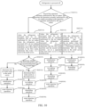
- the controller 14 is further configured to perform the steps S1 to S7.
- the step S1 when the refrigerator 1 is powered off, the operation currently performed by the ice maker 1001 is recorded, and the operation currently performed by the ice maker 1001 is determined according to the operation currently performed by the ice maker 1001.
- the step S2 is performed.
- the step S3 is performed.
- the step S4 is performed.
- step S2 when the refrigerator 1 is powered back on, on a condition that an operation performed by the ice maker 1001 when the refrigerator 1 was powered off is an ice making operation or a water injection operation, and the flow meter 16 detects a flow pulse when the ice maker 1001 performs the water injection operation, it is determined that water may exist in the mold cavity 330, and the step S5 is performed.
- step S3 when the refrigerator 1 is powered back on, on a condition that an operation performed by the ice maker 1001 when the refrigerator 1 was powered off is an initialization operation, it is determined that the first mold portion 310 and the second mold portion 320 are in a separated state and no water exists in the mold cavity 330, and the step S11 is performed.
- the first mold portion 310 and the second mold portion 320 may be in a process of moving from the closed state to the separated state, or in a process of moving from the separated state to the closed state.
- the controller 14 can determine that no water exists in the mold cavity. In this case, the controller 14 needs to control the ice maker 1001 to perform the step S11 again to perform the initialization operation again.
- step S4 when the refrigerator 1 is powered back on, on a condition that the operation performed by the ice maker 1001 when the refrigerator 1 was powered off is a demolding operation, it is determined that no water exists in the mold cavity 330 but ice may exist.
- the ice maker 1001 is controlled to perform the step S11 and then perform the step S13.
- the controller 14 can assume that ice exists in the mold cavity 330 by default, and control the ice maker 1001 to perform the step S11 to drive the first mold portion 310 and the second mold portion 320 to move to a closed state. Step S12 is skipped then, and the controller 14 controls the ice maker 1001 to perform the step S13 to perform a demolding operation.
- the controller 14 controls the ice maker 1001 to perform the step S13, it can further control the ice maker 1001 to perform the step S14, i.e., inject water into the mold cavity 330.
- the controller 14 can immediately start to perform the step S12, i.e., the ice making operation.
- step S5 it is determined whether the first mold portion 310 and the second mold portion 320 are in a closed state. If yes, the step S6 is performed, and if not, the step S7 is performed.
- step S6 it is determined that water exists in the mold cavity 330, and the ice maker 1001 is controlled to perform the step S12.
- the controller 14 determines that the operation performed by the ice maker 1001 is an ice making operation or a water injection operation, a flow pulse is recorded in the flow meter 16, and the first mold portion 310 and the second mold portion 320 are in the closed state, it can be determined that water exists in the mold cavity 330. In this case, the controller 14 can control the ice maker 1001 to directly perform the step S12 to make ice.
- the controller 14 is further configured to control the ice maker 1001 to perform the steps S13 and S14 to perform a demolding operation and a water injection operation.
- the step S12 can be immediately performed for the next round of ice making process.
- step S7 it is determined that no water exists in the mold cavity 330, and the ice maker 1001 is controlled to perform the steps S11 and S14.
- the controller 14 determines that the first mold portion 310 and the second mold portion 320 are not in the closed state, it can be determined that no water exists in the mold cavity 330. In this case, the controller 14 controls the ice maker 1001 to first perform the step S11 to ensure that the first mold portion 310 and the second mold portion 320 are in the closed state. Then, without performing the steps S12 and S13, the controller 14 controls the ice maker 1001 to directly perform the step S14 to perform the water injection operation.
- the controller 14 is further configured to control the ice maker 1001 to perform the steps S12 to S13 to complete the ice making process that was not completed by the ice maker 1001 before the refrigerator 1 is powered off.
- the determination of the state of the first mold portion 310 and the second mold portion 320 is made according to a position switch installed on the first mold portion 310 and the second mold portion 320 or by identifying current of a motor.
- the driving mechanism 500 includes a motor 510.
- the motor 510 is connected to at least one of the first shell portion 210 or the second shell portion 220, and is configured to drive at least one of the first shell portion 210 and the second shell portion 220 to move, thereby driving at least one of the first mold portion 310 or the second mold portion 320 to move.
- the rotation speed of the motor 510 can be variable.
- the rotation speed of the motor 510 is inversely proportional to an output torque, i.e., when the rotation speed of the motor 510 increases, the output torque decreases, and when the rotation speed of the motor 510 decreases, the output torque increases.
- the rotation speed of the motor 510 is a first preset rotation speed V1.
- the rotation speed of the motor 510 is a second preset rotation speed V2.
- the second preset rotation speed V2 is less than the first preset rotation speed V1, i.e., the torque output by the motor 510 during the demolding operation of the ice maker 1001 is greater than the torque output by the motor 510 during the initialization operation of the ice maker 1001.
- first preset rotation speed V1 and the second preset rotation speed V2 are values pre-calculated and set in the driving mechanism 500, which can be set and adjusted according to actual conditions such as a structural size of the ice maker 1001, which is not limited in the present disclosure.
- the ice maker 1001 further includes a heating assembly 5, which is connected to at least one of the first mold portion 310 or the second mold portion 320 and is coupled to the controller 14.
- the controller 14 is also configured to control the heating assembly 5 to heat at least one of the first mold portion 310 or the second mold portion 320.
- the heating assembly 5 is a heating wire or a heating rod.
- the step S13 includes a step S131 and a step S132.
- the heating assembly 5 is controlled to heat at least one of the first mold portion 310 or the second mold portion 320, causing that the ice block in at least one of the first mold portion 310 or the second mold portion 320 is slightly melted.
- the ice maker 1001 further includes a second temperature sensor, which is disposed on a side surface of the first mold portion 310 (i.e., the first sub-mold shell 401) away from the second mold portion 320 (i.e., the second sub-mold shell 402), and is configured to detect a surface temperature of the first mold portion 310.
- the controller 14 is coupled to the second temperature sensor, thereby realizing information exchange with the second temperature sensor to obtain the surface temperature of the first mold portion 310 detected by the second temperature sensor.
- the controller 14 controls the heating assembly 5 to heat the first mold portion 310, and when the second temperature sensor detects that the surface temperature of the first mold portion 310 reaches a second preset temperature threshold T (i.e., a preset temperature threshold), the ice maker is controlled to perform the step S132.
- the second preset temperature threshold T is, for example, 5°C to 6°C.
- the second preset temperature threshold T can be set and adjusted according to actual conditions, which is not limited in the present disclosure.
- the controller 14 controls the heating assembly 5 to heat the first mold portion 310.
- the heating time of the heating assembly 5 reaches a preset heating time
- the ice maker 1001 is controlled to perform the step S132.
- the driving mechanism 500 is controlled to drive at least one of the first mold portion 310 or the second mold portion 320 to move toward at least one of the corresponding first ejecting rod 410 or second ejecting rod 420, causing that the ice block in the first mold portion 310 and the second mold portion 320 is ejected.
- controller 14 controls the driving mechanism 500 to drive the first mold portion 310 or the second mold portion 320 to open, it first controls the heating assembly 5 to heat at least one of the first mold portion 310 or the second mold portion 320, thereby facilitating the ice block to be ejected from the first mold portion 310 or the second mold portion 320.
- the controller 14 controls the heating assembly 5 to heat at least one of the first mold portion 310 or the second mold portion 320, and in the step S132, the controller 14 controls the heating assembly 5 to stop heating at least one of the first mold portion 310 or the second mold portion 320.
- the controller 14 controls the heating assembly 5 to heat at least one of the first mold portion 310 or the second mold portion 320. In this way, when at least one of the first mold portion 310 or the second mold portion 320 comes into contact with at least one of the corresponding first ejecting rods 410 or second ejecting rods 420, it facilitates ejection of the ice block from the first mold portion 310 or the second mold portion 320.
- the controller 14 controls the driving mechanism 500 to drive at least one of the first mold portion 310 or the second mold portion 320 to move toward the corresponding at least one of the first ejecting rod 410 or the second ejecting rod 420 to reach a second preset number of steps X2
- the controller 14 controls the heating assembly 5 to heat at least one of the first mold portion 310 or the second mold portion 320.
- the second preset number of steps X2 is less than a total number of steps X0 required for at least one of the first mold portion 310 or the second mold portion 320 to contact at least one of the first ejecting rod 410 or the second ejecting rod 420.
- the following describes the movement process of the second sub-mold shell 402 in the above demolding operation by taking the example that the driving mechanism 500 only drives the second sub-mold shell 402 to move. It should be noted that in the above demolding operation, the movement process of the first sub-mold shell 401 and the second sub-mold shell 402 is similar, which will not be described in detail in this disclosure.
- the position of the second sub-mold shell 402 is considered as the initial position, and when the second sub-mold shell 402 presses the second ejecting rod 420, the position of the second sub-mold shell 402 is considered as a final position. Then, a number of steps required for the driving mechanism 500 to drive the second sub-mold shell 402 to move from the initial position to the final position is the total number of steps X0.
- the controller 14 detects the number of movement steps of the second sub-mold shell 402 in real time, and a current movement position of the second sub-mold shell 402 can be obtained.
- the controller 14 when the controller 14 detects that a current number of movement steps of the second sub-mold shell 402 reaches the total number of steps X0, it can be determined that the second sub-mold shell 402 is in contact with the second ejecting rod 420. In this case, the controller 14 controls the driving mechanism 500 to stop driving the second sub-mold shell 402 to move.
- the controller 14 controls the heating assembly 5 to heat the second sub-mold shell 402, so that a part of the ice block close to an inner surface of the second sub-mold shell 402 is melted, causing that the second ejecting rod 420 can eject the ice block from the mold cavity 330 to make the ice block fall into the ice storage box.
- the number of steps required for the second mold shell 402 to move toward the second ejecting rod 420 to a position where the ice block can fall from a gap between the first mold shell 401 and the second mold shell 402 is preset as a third preset number of steps X3 (i.e., the number of demolding steps), and X2>X3.
- the second preset number of steps X2, the third preset number of steps X3 and the total number of steps X0 are pre-calculated and set values, which can be set and adjusted according to the actual situation such as the structural size of the ice maker, which is not limited in the present disclosure.
- the ice maker 1001 further includes at least one sensor device 700.
- the at least one sensor device 700 is connected to the mold shell 400.
- the at least one sensor device 700 is disposed on at least one side of the mold shell 400.
- a detection direction of the sensor device 700 is toward a plane where an opening of the first sub-mold shell 401 is located and a plane where an opening of the second sub-mold shell 402 is located.
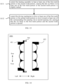
- the sensor device 700 is configured to detect whether there is an ice block in the first sub-mold shell 401 or the second sub-mold shell 402 when the first sub-mold shell 401 and the second sub-mold shell 402 are separated.
- At least one sensor device 700 is disposed on a side of the first sub-mold shell 401 along a length direction of the first sub-mold shell 401, or at least one sensor device 700 is disposed on a side of the second sub-mold shell 402 along a length direction of the second sub-mold shell 402.
- the at least one sensor device 700 includes two sensor devices 700, and the two sensor devices 700 are disposed on a side of the first sub-mold shell 401 and on a side of the second sub-mold shell 402 along a length direction of the first sub-mold shell 401 and the second sub-mold shell 402, respectively.
- the part of the ice block that protrudes from the plane where the opening of the first sub-mold shell 401 is located and the plane where the opening of the second sub-mold shell 402 is located is within a detection range of the sensor device 700. In this way, when the sensor device 700 detects existence of an obstacle within its detection range, it can be determined that there is an ice block in the first sub-mold shell 401 and /or the second sub-mold shell 402 that has not ejected.
- the controller 14 is further configured to perform a step S13A.
- the sensor device 700 is controlled to start to detect whether there is an ice block in the first sub-mold shell 401 or the second sub-mold shell 402. If yes, the step S13 is re-performed, and if not, the step S14 is performed.
- the controller 14 is further configured to perform a step S133.
- the sensor device 700 is controlled to start to detect whether there is an ice block in the first sub-mold shell 401 or the second sub-mold shell 402. If yes, the step S131 is re-performed, and if not, the step S14 is performed.
- a sensor device 700 is disposed in the ice maker 1001, which can directly and effectively detect whether the ice in the mold cavity 330 is successfully ejected after the ice maker 1001 completes the ice making operation and the demolding operation. Therefore, when the ice in the mold cavity 330 fails to be ejected, the controller 14 can control the ice maker 1001 to perform the demolding operation again to avoid water overflow due to demolding failure and freezing of various components in the ice maker 1001, thereby facilitating an operation stability of the ice maker 1001 and improving the user experience.
- the sensor device 700 is disposed on a side of the first sub-mold shell 401.
- the sensor device 700 is closer to the second sub-mold shell 402 than the plane where the opening of the first sub-mold shell 401 is located.
- the sensor device 700 is located between the first sub-mold shell 401 and the second sub-mold shell 402.
- the detection direction of the sensor device 700 is parallel to the plane where the opening of the first sub-mold shell 401 is located.
- the step S13A includes a step S13B and a step S13C.
- the driving mechanism 500 is controlled to drive at least one of the first sub-mold shell 401 or the second sub-mold shell 402 to move, so that the plane where the opening of the first sub-mold shell 401 is located is at the preset distance away from the plane where the opening of the second sub-mold shell 402 is located.
- the preset distance is less than or equal to half of at least one of a width, height or depth of the mold cavity 330. In this way, the detection accuracy of the sensor device 700 is improved.
- the sensor device 700 may not detect the ice block, resulting in a decrease in the accuracy of the detection.
- the sensor device 700 is controlled to start to detect whether there is an ice block between the plane where the opening of the first sub-mold shell 401 is located and the plane where the opening of the second sub-mold shell 402 is located. If yes, the step S13 is re-performed, and if not, the step S14 is performed.
- the refrigerator 1 only requires the sensor device 700 to be arranged on a side of the first sub-mold shell 401, without the need to arrange the sensor device 700 on the second sub-mold shell 402.
- the controller 14 controls the driving mechanism 500 to drive the first sub-mold shell 401 or the second sub-mold shell 402 to move, or drive the first sub-mold shell 401 and the second sub-mold shell 402 to move simultaneously, so that the plane where the opening of the first sub-mold shell 401 is located is at a preset distance from the plane where the opening of the second sub-mold shell 402 is located.
- the preset distance is set according to at least one of the width, height or depth of the mold cavity 330. In other words, the preset distance is set according to a radius of a formed ice block.
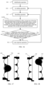
- the sensor device 700 when the first sub-mold shell 401 and the second sub-mold shell 402 are at a preset distance, the sensor device 700 is activated for detection, and at this time, whether the ice block is attached to the first sub-mold shell 401 (as shown in FIG. 17 ) or the second sub-mold shell 402 (as shown in FIG. 18 ), it can be detected by the sensor device 700 disposed on the side of the first sub-mold shell 401. In this way, the structure of the ice maker 1001 is effectively simplified, the circuit wiring is reduced, and the production cost is reduced.
- the mold shell 400 includes one or more mold cavities 330.
- the detection direction and method of the sensor device 700 can be adjusted according to the number and arrangement of the mold cavities 330.
- the detection direction of the sensor device 700 remains fixed.
- the mold shell 400 includes three mold cavities 330, and the three mold cavities 330 is arranged along the detection direction of the sensor device 700, so that the sensor device 700 can detect all three mold cavities 330 to detect whether there is an ice block in the three mold cavities 330.
- the detection direction of the sensor device 700 can rotate within a predetermined angle range in a direction parallel to the plane where the opening of the mold shell 400 is located, with a predetermined cycle.
- the predetermined angle range covers the area where the plurality of mold cavities 330 are located, so that the sensor device 700 can detect the plurality of mold cavities 330 to detect whether there is an ice block in the mold shell 400.
- the sensor device 700 includes an infrared sensor 710.
- the infrared sensor 710 includes an infrared transmitting end 711 and an infrared receiving end 712, the infrared transmitting end 711 is arranged on a side of the first sub-mold shell 401 or the second sub-mold shell 402, and the infrared receiving end 712 is arranged on the other side of the same sub-mold shell.
- the infrared transmitting end 711 is disposed on a side of the first sub-mold shell 401 along the length direction of the first sub-mold shell 401
- the infrared receiving end 712 is disposed on the other side of the first sub-mold shell 401 along the length direction of the first sub-mold shell 401.
- the infrared transmitting end 711 When the infrared sensor 710 is in operation, the infrared transmitting end 711 emits an infrared signal in the detection direction. In this case, on a condition that an ice block is in the first sub-mold shell 401 and/or the second sub-mold shell 402, propagation of the infrared signal will be blocked by the ice block, and the infrared receiving end 712 cannot receive the infrared signal. On a condition that no ice block is in the first sub-mold shell 401 and the second sub-mold shell 402, the infrared receiving end 712 can receive the infrared signal. Based on this, depending on whether the infrared receiving end 712 receives the infrared signal emitted by the infrared transmitting end 711, it can be determined whether there is an ice block in the mold 400.
- the sensor device 700 includes a radar sensor 720.
- the radar sensor 720 is disposed on a side of the first sub-mold shell 401 or the second sub-mold shell 402.
- the radar sensor 720 is disposed on a side of the first sub-mold shell 401 along the length direction of the first sub-mold shell 401.
- the radar sensor 720 can detect objects by emitting microwaves, sound waves or lasers and receiving echoes. When the radar sensor 720 is in operation, it will emit microwaves, sound waves or laser signals in the detection direction. If the radar sensor 720 receives an echo signal within a preset time, it indicates that there is an ice block in the first sub-mold shell 401 and/or the second sub-mold shell 402. Otherwise, it indicates that there is no ice block in the first sub-mold shell 401 and the second sub-mold shell 402.
- the radar sensor 720 is also configured to detect a distance between itself and the ice block when detecting presence of the ice block in the mold shell, so that the controller 14 can determine the position of the mold cavity 330 where the ice block is located based on the distance detected by the radar sensor 720.
- the heating assembly 5 can heat the mold cavity 330 where the ice block is located.
- the heating assembly includes heating wires, which are disposed in the mold shell 400 and correspond to the plurality of mold cavities 330, respectively.
- the controller 14 determines that a mold cavity 330 among the plurality of mold cavities 330 needs to be heated, the corresponding heating wire can be controlled to be energized for operation. In this way, the energy consumption of the refrigerator 1 is reduced.
- the ice maker 1001 further includes a fault alarm device, which is coupled to the controller 14 and is configured to issue a fault alarm message under the control of the controller 14.
- the controller 14 is further configured to perform a step S21 and a step S22.
- step S21 a number of times the ice maker 1001 performs the demolding operation in a current ice making process is obtained.
- step S22 when the number of times the ice maker 1001 performs the demolding operation reaches a preset number, the fault alarm device is controlled to send a fault alarm message.
- the controller 14 controls the ice maker 1001 to perform the demolding operation again (i.e., the step S13). Therefore, when the number of times the ice maker 1001 continuously performs the demolding operation reaches a preset number, it means that the ice maker 1001 has a fault that cannot be eliminated by itself. In this case, the controller 14 controls the fault alarm device to issue a corresponding fault alarm message to remind the user that the ice maker 1001 has a fault. When receiving the fault alarm message, the user can ask a maintenance personnel to eliminate the fault, thereby ensuring the normal operation of the ice maker.
- the refrigerator 1 described in any of the above embodiments is refrigerated by the refrigeration system to provide cold air to the storage compartment so that the storage compartment is maintained at a constant low temperature.
- the refrigeration system includes a compressor, a condenser, a drying filter, a capillary tube and an evaporator, and a refrigeration cycle of the refrigeration system includes a compression process, a condensation process, a throttling process and an evaporation process.
- the refrigerator is powered on and the compressor starts working.
- the low-temperature, low-pressure refrigerant is sucked into the compressor, compressed into a high-temperature, high-pressure superheated gaseous refrigerant in a cylinder of the compressor, and then discharged into the condenser.
- the high-temperature, high-pressure gaseous refrigerant dissipates heat through the condenser with the temperature continuously dropping, and it is cooled to a saturated gaseous refrigerant at room temperature and high pressure.
- the saturated gaseous refrigerant at room temperature and high pressure is further cooled to a saturated liquid refrigerant, the temperature of the refrigerant no longer drops. At this time, the temperature of the refrigerant is called a condensation temperature.
- the pressure of the refrigerant remains almost unchanged during the condensation process.
- the condensed saturated liquid refrigerant passes through a drying filter to remove moisture and impurities and then flows into the capillary tube, where it is throttled and depressurized to become a wet gaseous refrigerant at room temperature and low pressure.
- the refrigerant enters the evaporator, absorbs heat, and vaporizes to reduce the temperature of the evaporator and its surroundings, and becomes a low-temperature, low-pressure gaseous refrigerant.
- the refrigerant coming out of the evaporator returns to the compressor again, and the above process is repeated to transfer heat in the refrigerator to air outside the refrigerator, thereby achieving refrigeration of the refrigerator 1.
- a method for controlling a refrigerator is further provided, which can be applied in the refrigerator described in any of the above-mentioned embodiments (i.e., corresponding to FIGS. 1-21 ).
- the method includes steps S101 to S104.
- an initialization operation is performed, which is configured to control the driving mechanism 500 to drive the first mold portion 310 and the second mold portion 320 to open by a preset number of steps, and then drive the first mold portion 310 and the second mold portion 320 to close.
- an ice making operation is performed, which is configured to start ice making in response to an ice making control instruction until a preset ice making time is reached.
- a demolding operation is performed, which is configured to control the driving mechanism 500 to drive at least one of the first mold portion 310 or the second mold portion 320 to move toward at least one of the corresponding first ejecting rod 410 or second ejecting rod 420, such that the ice block in the first mold portion 310 and the second mold portion 320 is ejected.
- a water injection operation is performed, which is configured to control the driving mechanism 500 to drive the first mold portion 310 and the second mold portion 320 to close, and control the water injection assembly 15 to inject a preset amount of water into the mold cavity 330.
- the step S102 is then performed again.
- the method further includes steps S111 to S117.
- the step S111 when the refrigerator 1 is powered off, the operation currently performed by the ice maker 1001 is recorded, and the operation currently performed by the ice maker 1001 is determined according to the operation currently performed by the ice maker 1001.
- the step S112 is performed.
- the step S113 is performed.
- the step S114 is performed.
- step S112 when the refrigerator 1 is powered back on, on a condition that an operation performed by the ice maker 1001 when the refrigerator 1 was powered off is an ice making operation or a water injection operation, and a flow pulse is recorded in the flow meter 16, it is determined that water may exist in the mold cavity 330.
- the step S115 is then performed.
- step S113 when the refrigerator 1 is powered back on, on a condition that an operation performed by the ice maker 1001 when the refrigerator 1 was powered off is an initialization operation, it is determined that the first mold portion 310 and the second mold portion 320 are in a separated state and no water exists in the mold cavity 330.
- the step S101 is then performed.
- step S114 when the refrigerator 1 is powered back on, on a condition that the operation performed by the ice maker 1001 when the refrigerator 1 was powered off is a demolding operation, it is determined that no water exists in the mold cavity 330 but ice may exist.
- the ice maker 1001 is controlled to perform the step S101 and then perform the step S103.
- step S115 it is determined whether the first mold portion 310 and the second mold portion 320 are in a closed state. If yes, the step S116 is performed, and if not, the step S117 is performed.
- step S116 it is determined that water exists in the mold cavity 330, and the ice maker 1001 is controlled to perform the step S102.
- step S117 it is determined that no water exists in the mold cavity 330, and the ice maker 1001 is controlled to perform the step S101 and the step S104.
- the controller 14 is further configured to perform a step S103A.
- the sensor device 700 is controlled to start to detect whether there is an ice block in the first sub-mold shell 401 or the second sub-mold shell 402. If yes, the step S103 is re-performed, and if not, the step S104 is performed.
- Some embodiments of the present disclosure provide a computer-readable storage medium (e.g., a non-transitory computer-readable storage medium) on which computer program instructions are stored.
- a computer-readable storage medium e.g., a non-transitory computer-readable storage medium
- the controller 14 performs the above-mentioned method for controlling a refrigerator.
- the above-mentioned computer-readable storage media may include, but are not limited to: a magnetic storage device (e.g., a hard disk, a floppy disk, or a magnetic tape, etc.), an optical disk (e.g., a CD (Compact Disk), a DVD (Digital Versatile Disk), etc.), a smart card, and a flash memory device (e.g., EPROM (Erasable Programmable Read-Only Memory), a card, a stick, or a key drive, etc.).
- the various computer-readable storage media described in the embodiments of the present disclosure may represent one or more devices and/or other machine-readable storage media for storing information.
- the term "machine-readable storage medium" may include, but is not limited to, wireless channels and various other media capable of storing, containing, and/or carrying instructions and/or data.
- a computer program product includes computer program instructions (the computer program instructions are, for example, stored on a non-transitory computer-readable storage medium), and when the computer program instructions are executed on a computer, the computer program instructions cause the computer to perform the method for controlling a refrigerator as described above.
- a computer program is provided.
- the computer program When the computer program is executed on a computer, the computer program enables the computer to perform the control method for the refrigerator as described above.
Landscapes
- Engineering & Computer Science (AREA)
- Physics & Mathematics (AREA)
- Mechanical Engineering (AREA)
- Thermal Sciences (AREA)
- General Engineering & Computer Science (AREA)
- Chemical & Material Sciences (AREA)
- Combustion & Propulsion (AREA)
- Production, Working, Storing, Or Distribution Of Ice (AREA)
- Moulds For Moulding Plastics Or The Like (AREA)
Applications Claiming Priority (3)
| Application Number | Priority Date | Filing Date | Title |
|---|---|---|---|
| CN202210759347.9A CN117367008B (zh) | 2022-06-30 | 一种冰箱、制冰机及制冰机控制方法 | |
| CN202211126022.3A CN117760139A (zh) | 2022-09-16 | 2022-09-16 | 一种由合模形成模腔的制冰机和冰箱 |
| PCT/CN2023/104927 WO2024002354A1 (fr) | 2022-06-30 | 2023-06-30 | Réfrigérateur et son procédé de commande |
Publications (2)
| Publication Number | Publication Date |
|---|---|
| EP4549845A1 true EP4549845A1 (fr) | 2025-05-07 |
| EP4549845A4 EP4549845A4 (fr) | 2025-10-08 |
Family
ID=89383365
Family Applications (1)
| Application Number | Title | Priority Date | Filing Date |
|---|---|---|---|
| EP23830517.1A Pending EP4549845A4 (fr) | 2022-06-30 | 2023-06-30 | Réfrigérateur et son procédé de commande |
Country Status (5)
| Country | Link |
|---|---|
| US (1) | US20250093086A1 (fr) |
| EP (1) | EP4549845A4 (fr) |
| CN (1) | CN117769635A (fr) |
| AU (1) | AU2023297727B2 (fr) |
| WO (1) | WO2024002354A1 (fr) |
Family Cites Families (8)
| Publication number | Priority date | Publication date | Assignee | Title |
|---|---|---|---|---|
| JP3117851B2 (ja) * | 1993-08-31 | 2000-12-18 | 株式会社東芝 | 自動製氷機付き冷蔵庫 |
| KR19990013143A (ko) * | 1997-07-31 | 1999-02-25 | 윤종용 | 제빙기의 이빙제어장치 및 그 방법 |
| KR100565496B1 (ko) * | 2003-10-07 | 2006-03-30 | 엘지전자 주식회사 | 냉장고용 제빙기의 급속 제빙 제어 방법 |
| US7216491B2 (en) * | 2005-04-29 | 2007-05-15 | Emerson Electric Co | Ice maker with adaptive fill |
| CN103851877B (zh) * | 2014-02-28 | 2016-01-20 | 海信容声(广东)冰箱有限公司 | 一种冰箱自动制冰机系统的控制方法 |
| WO2020071765A1 (fr) * | 2018-10-02 | 2020-04-09 | 엘지전자 주식회사 | Réfrigérateur |
| CN213040838U (zh) * | 2020-07-08 | 2021-04-23 | 海信(山东)冰箱有限公司 | 一种冰箱 |
| CN113237284B (zh) * | 2021-05-28 | 2023-12-22 | 海信容声(广东)冰箱有限公司 | 一种冰箱 |
-
2023
- 2023-06-30 WO PCT/CN2023/104927 patent/WO2024002354A1/fr not_active Ceased
- 2023-06-30 EP EP23830517.1A patent/EP4549845A4/fr active Pending
- 2023-06-30 CN CN202380013053.4A patent/CN117769635A/zh active Pending
- 2023-06-30 AU AU2023297727A patent/AU2023297727B2/en active Active
-
2024
- 2024-12-05 US US18/970,862 patent/US20250093086A1/en active Pending
Also Published As
| Publication number | Publication date |
|---|---|
| AU2023297727A1 (en) | 2025-01-02 |
| US20250093086A1 (en) | 2025-03-20 |
| EP4549845A4 (fr) | 2025-10-08 |
| WO2024002354A1 (fr) | 2024-01-04 |
| CN117769635A (zh) | 2024-03-26 |
| AU2023297727B2 (en) | 2026-03-12 |
Similar Documents
| Publication | Publication Date | Title |
|---|---|---|
| EP2419685B1 (fr) | Technologie concernant un réfrigérateur | |
| EP3189292B1 (fr) | Dispositif d'ouverture et de fermeture de porte destiné à un réfrigérateur | |
| EP1684036B1 (fr) | Distributeur de glace et de l'eau sur la porte d'un réfrigérateur | |
| US3788089A (en) | Combination ice cube maker and refrigerator | |
| US12209797B2 (en) | Refrigerator and method for controlling refrigerator | |
| KR101684054B1 (ko) | 냉장고 및 그 제어방법 | |
| JP5832937B2 (ja) | 冷蔵庫 | |
| US20080092574A1 (en) | Cooler with multi-parameter cube ice maker control | |
| US20230349613A1 (en) | Refrigerator | |
| EP4549845A1 (fr) | Réfrigérateur et son procédé de commande | |
| KR20180052312A (ko) | 냉장고 및 그 제어 방법 | |
| CN117367008B (zh) | 一种冰箱、制冰机及制冰机控制方法 | |
| KR100281838B1 (ko) | 냉장고의 홈바룸 온도제어 장치 | |
| CN117367008A (zh) | 一种冰箱、制冰机及制冰机控制方法 | |
| JP7495164B2 (ja) | 冷蔵庫 | |
| US20250334318A1 (en) | Refrigerator and control method of refrigerator | |
| US20260071809A1 (en) | Refrigerator and method for controlling the same | |
| CN219756735U (zh) | 冰箱 | |
| EP4556828A1 (fr) | Réfrigérateur | |
| US20260104195A1 (en) | Refrigerator and controlling method for same | |
| US20250297793A1 (en) | Refrigerator and control method thereof | |
| CN117760139A (zh) | 一种由合模形成模腔的制冰机和冰箱 | |
| US20250283657A1 (en) | Refrigerator and method for controlling refrigerator | |
| KR20250177613A (ko) | 냉장고 | |
| KR20260027709A (ko) | 냉장고 및 그의 제어방법 |
Legal Events
| Date | Code | Title | Description |
|---|---|---|---|
| STAA | Information on the status of an ep patent application or granted ep patent |
Free format text: STATUS: THE INTERNATIONAL PUBLICATION HAS BEEN MADE |
|
| PUAI | Public reference made under article 153(3) epc to a published international application that has entered the european phase |
Free format text: ORIGINAL CODE: 0009012 |
|
| STAA | Information on the status of an ep patent application or granted ep patent |
Free format text: STATUS: REQUEST FOR EXAMINATION WAS MADE |
|
| 17P | Request for examination filed |
Effective date: 20241204 |
|
| AK | Designated contracting states |
Kind code of ref document: A1 Designated state(s): AL AT BE BG CH CY CZ DE DK EE ES FI FR GB GR HR HU IE IS IT LI LT LU LV MC ME MK MT NL NO PL PT RO RS SE SI SK SM TR |
|
| A4 | Supplementary search report drawn up and despatched |
Effective date: 20250904 |
|
| DAV | Request for validation of the european patent (deleted) | ||
| DAX | Request for extension of the european patent (deleted) | ||
| RIC1 | Information provided on ipc code assigned before grant |
Ipc: F25C 1/10 20060101AFI20250829BHEP Ipc: F25C 1/24 20180101ALI20250829BHEP Ipc: F25D 29/00 20060101ALI20250829BHEP Ipc: F25C 1/04 20180101ALI20250829BHEP Ipc: F25C 1/25 20180101ALI20250829BHEP Ipc: F25C 5/08 20060101ALI20250829BHEP Ipc: F25C 5/20 20180101ALI20250829BHEP |