EP4549890A1 - Détection acoustique distribuée à portées multiples à partir du rivage avec différentes plages de fréquences de détection et longueurs de portée de détection - Google Patents
Détection acoustique distribuée à portées multiples à partir du rivage avec différentes plages de fréquences de détection et longueurs de portée de détection Download PDFInfo
- Publication number
- EP4549890A1 EP4549890A1 EP24209130.4A EP24209130A EP4549890A1 EP 4549890 A1 EP4549890 A1 EP 4549890A1 EP 24209130 A EP24209130 A EP 24209130A EP 4549890 A1 EP4549890 A1 EP 4549890A1
- Authority
- EP
- European Patent Office
- Prior art keywords
- das
- station
- loopbacks
- wavelength
- signal
- Prior art date
- Legal status (The legal status is an assumption and is not a legal conclusion. Google has not performed a legal analysis and makes no representation as to the accuracy of the status listed.)
- Pending
Links
Images



Classifications
-
- G—PHYSICS
- G01—MEASURING; TESTING
- G01H—MEASUREMENT OF MECHANICAL VIBRATIONS OR ULTRASONIC, SONIC OR INFRASONIC WAVES
- G01H9/00—Measuring mechanical vibrations or ultrasonic, sonic or infrasonic waves by using radiation-sensitive means, e.g. optical means
- G01H9/004—Measuring mechanical vibrations or ultrasonic, sonic or infrasonic waves by using radiation-sensitive means, e.g. optical means using fibre optic sensors
-
- G—PHYSICS
- G01—MEASURING; TESTING
- G01D—MEASURING NOT SPECIALLY ADAPTED FOR A SPECIFIC VARIABLE; ARRANGEMENTS FOR MEASURING TWO OR MORE VARIABLES NOT COVERED IN A SINGLE OTHER SUBCLASS; TARIFF METERING APPARATUS; MEASURING OR TESTING NOT OTHERWISE PROVIDED FOR
- G01D5/00—Mechanical means for transferring the output of a sensing member; Means for converting the output of a sensing member to another variable where the form or nature of the sensing member does not constrain the means for converting; Transducers not specially adapted for a specific variable
- G01D5/26—Mechanical means for transferring the output of a sensing member; Means for converting the output of a sensing member to another variable where the form or nature of the sensing member does not constrain the means for converting; Transducers not specially adapted for a specific variable characterised by optical transfer means, i.e. using infrared, visible, or ultraviolet light
- G01D5/32—Mechanical means for transferring the output of a sensing member; Means for converting the output of a sensing member to another variable where the form or nature of the sensing member does not constrain the means for converting; Transducers not specially adapted for a specific variable characterised by optical transfer means, i.e. using infrared, visible, or ultraviolet light with attenuation or whole or partial obturation of beams of light
- G01D5/34—Mechanical means for transferring the output of a sensing member; Means for converting the output of a sensing member to another variable where the form or nature of the sensing member does not constrain the means for converting; Transducers not specially adapted for a specific variable characterised by optical transfer means, i.e. using infrared, visible, or ultraviolet light with attenuation or whole or partial obturation of beams of light the beams of light being detected by photocells
- G01D5/353—Mechanical means for transferring the output of a sensing member; Means for converting the output of a sensing member to another variable where the form or nature of the sensing member does not constrain the means for converting; Transducers not specially adapted for a specific variable characterised by optical transfer means, i.e. using infrared, visible, or ultraviolet light with attenuation or whole or partial obturation of beams of light the beams of light being detected by photocells influencing the transmission properties of an optical fibre
- G01D5/35383—Mechanical means for transferring the output of a sensing member; Means for converting the output of a sensing member to another variable where the form or nature of the sensing member does not constrain the means for converting; Transducers not specially adapted for a specific variable characterised by optical transfer means, i.e. using infrared, visible, or ultraviolet light with attenuation or whole or partial obturation of beams of light the beams of light being detected by photocells influencing the transmission properties of an optical fibre using multiple sensor devices using multiplexing techniques
-
- H—ELECTRICITY
- H04—ELECTRIC COMMUNICATION TECHNIQUE
- H04B—TRANSMISSION
- H04B10/00—Transmission systems employing electromagnetic waves other than radio-waves, e.g. infrared, visible or ultraviolet light, or employing corpuscular radiation, e.g. quantum communication
- H04B10/07—Arrangements for monitoring or testing transmission systems; Arrangements for fault measurement of transmission systems
- H04B10/071—Arrangements for monitoring or testing transmission systems; Arrangements for fault measurement of transmission systems using a reflected signal, e.g. using optical time domain reflectometers [OTDR]
Definitions
- Embodiments of the present disclosure relate to the field of optical communication systems.
- the present disclosure relates to techniques for extending and improving the sensitivity of distributed acoustic sensing (DAS) in subsea optical cables.
- DAS distributed acoustic sensing
- an optical cable may be used to provide continuous real-time or near real-time monitoring of perturbances or anomalies in the vicinity of the fiber optic cable (hereinafter cable), and up to many kilometers from the cable.
- the cable itself may be used as a distributed sensing element to detect or monitor different types of disruptions, interferences, irregularities, activities whether natural or man-made occurring in or out of the undersea environment, etc. as acoustic vibrations in the DAS sensing environment (e.g., oceanic and terrestrial environment,).
- optoelectronic devices/equipment coupled to the cable of the DAS system may detect, and process reflected light signals (e.g., Rayleigh backscatter signals or simply Rayleigh signal) over a distance (range) in the DAS sensing environment.
- reflected light signals e.g., Rayleigh backscatter signals or simply Rayleigh signal
- a DAS system may include a cable station equipped with a DAS Interrogator Unit (IU) that typically includes a DAS transmitter and receiver to probe a fiber optic cable using a coherent laser pulse, where changes in the phase of the returning optical backscattered signal are measured.
- IU DAS Interrogator Unit
- Optical phase shift between the received backscattered pulses may be proportional to strain in the fiber, leading to the ability to detect vibrations and the like, as measured by the effect of such perturbations on the phase.
- a DAS system based on Rayleigh back scattering also referred to as a Rayleigh-scattering-based DAS system in prior art.
- DAS IUs have been limited to cable lengths in the range of approximately 50 km for practical technology, and up to 150 km in experimental research units. Therefore, in a repeatered system that is equipped with Erbium doped fiber amplifiers (EDFA), just the first cable span (or span hereinafter) that is adjacent to the DAS IU can be sensed.
- EDFA Erbium doped fiber amplifiers
- DAS IUs may be placed in each optical repeater of the subsea link, where the sensing data collected would need to be transmitted to either shore end across the same optical cable that carries commercial optical signals.
- Another approach for DAS sensing is to make measurements through multiple amplified spans from a single DAS IU located on shore.
- a long subsea link up to 10,000 km, for example
- using just one DAS IU on either shore end of the system similar to the Coherent Optical Time Domain Reflectometry (C-OTDR) or Line Monitoring Equipment-Optical Time Domain Reflectometry (LME-OTDR) measurements deployed in some current commercial systems
- C-OTDR Coherent Optical Time Domain Reflectometry
- LME-OTDR Line Monitoring Equipment-Optical Time Domain Reflectometry
- a system for distributed acoustic sensing system may include a first distributed acoustic sensing (DAS) station, comprising a first plurality of interrogator units to launch a first plurality of DAS signals in a first direction.
- DAS distributed acoustic sensing
- a first interrogator unit of the first DAS station may be configured to launch a first DAS signal at a first interrogation rate and a first wavelength
- a second interrogator unit of the first DAS station is configured to launch a second DAS signal at a second wavelength and a second interrogation rate, that is less than the first interrogation rate.
- the system may include a loopback array, comprising a plurality of loopbacks, arranged over a plurality of spans, wherein a first set of proximate loopbacks nearest to the first DAS station are configured to route back the first DAS signal to the first DAS station, and wherein a first set of intermediate loopbacks, located further from the first DAS station, are configured to route back the second DAS signal to the first DAS station.
- a loopback array comprising a plurality of loopbacks, arranged over a plurality of spans, wherein a first set of proximate loopbacks nearest to the first DAS station are configured to route back the first DAS signal to the first DAS station, and wherein a first set of intermediate loopbacks, located further from the first DAS station, are configured to route back the second DAS signal to the first DAS station.
- a system for distributed acoustic sensing may include a first distributed acoustic sensing (DAS) station, located at a first end of a multi-span link, and configured to launch a plurality of DAS signals in a first direction.
- the system may include a second distributed acoustic sensing (DAS) station, located at a second end of the multi-span link, and configured to launch a plurality of DAS signals in a second direction.
- DAS distributed acoustic sensing
- the system may include a loopback array, comprising a first set of proximate loopbacks, located nearest to the first DAS station; a first set of intermediate loopbacks; a second set of proximate loopbacks, located nearest to the second DAS station; and a second set of intermediate loopbacks, located closer to the second DAS station than the first set of intermediate loopbacks.
- a loopback array comprising a first set of proximate loopbacks, located nearest to the first DAS station; a first set of intermediate loopbacks; a second set of proximate loopbacks, located nearest to the second DAS station; and a second set of intermediate loopbacks, located closer to the second DAS station than the first set of intermediate loopbacks.
- a first wavelength and a first interrogation rate of a first set of DAS signals routed through the first set of proximate loopbacks may differ from a second wavelength and a second interrogation rate of a second set of DAS signals routed through the first set of intermediate loopbacks, and wherein a third wavelength and a third interrogation rate of a third set of DAS signals routed through the second set of proximate loopbacks differs from a fourth wavelength and a fourth interrogation rate of a fourth set of DAS signals routed through the second set of intermediate loopbacks.
- a method for distributed acoustic sensing may include launching a first DAS signal from a first interrogator unit of a first DAS station at a first interrogation rate and a first wavelength and launching a second DAS signal from a second interrogator unit of the first DAS station at a second wavelength and a second interrogation rate, less than the first interrogation rate.
- the method may include routing back the first DAS signal to the first DAS station through a loopback of a first set of proximate loopbacks nearest to the first DAS station, and routing back the second DAS signal to the first DAS station through a loopback of a first set of intermediate loopbacks, located further from the first DAS station.
- Novel DAS apparatus, systems, architecture, and techniques are provided to improve DAS sensing capability, in particular, sensitivity and range across multiple spans of a subsea system including above ground and underground optical cables.
- the present embodiments provide architecture and methods for DAS sensing that may tailor the monitoring of different activities or events according to location over a large range up to thousands of kilometers in a subsea environment.
- a subsea sensing system there are different activities that may take place in the vicinity or along the length of a cable that may be detected and monitored, resulting in different measured acoustic frequencies or frequency signatures.
- Close to the shore e.g., ⁇ 100 km away
- ship activity may be the most important events to be monitored.
- the present embodiments tailor DAS sensing along a multi-span subsea cable system based upon the span location.
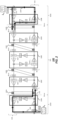
- FIG. 1 illustrates an example of a DAS system, shown as system 100, according to embodiments of the disclosure.
- the system 100 is formed of two terminal DAS cable stations (a cable station equipped with DAS Interrogator Unit or a DAS station hereinafter) that may be located at opposite ends of - a subsea cable system, where a first DAS station is shown as DAS station 102A with DAS IU 103A, and a second DAS station is shown as DAS station 102B with DAS IU 103B, where each DAS station may be located on shore.
- Each of the DAS stations may include a plurality of interrogator units (IUs) that are designed to independently launch DAS signals at different wavelengths.
- IUs interrogator units
- the IU wavelengths are designated as ⁇ 1, ⁇ 2 at one station and ⁇ 3, ⁇ 4 at the 2nd station.
- the IU wavelengths are designated as ⁇ 1, ⁇ 2, ⁇ 5 at one station and ⁇ 3, ⁇ 4, ⁇ 6 at the 2nd station.
- the wavelengths sent from the first DAS cable station may be the same as the wavelengths sent from the second DAS cable station (as explained later); for example in the specific example of FIG.
- the separate IUs are represented in FIG. 1 by the different wavelengths, ⁇ 1, ⁇ 2 and ⁇ 3 in the case of DAS station 102A, and ⁇ 1, ⁇ 2 and ⁇ 4, in the case of DAS station 102B.
- the two DAS stations may connect to a single fiber pair of a cable, where one fiber of the fiber pair may be designed to transmit DAS signals on a path 116, from ⁇ west' to ⁇ east' in FIG. 1 , while the other fiber of the fiber pair may transmit DAS signals from east to west along path 118.
- the different DAS stations of the system 100 may transmit on an optimized number of monitoring wavelengths, so that together the entire subsea link can be monitored.
- the DAS pulses from the three DAS IUs may be synchronized and staggered in time.
- the link 101 between the DAS station 102A and DAS station 102B is characterized by a series of cable spans, shown as span 120A, span 120B, span 120C, and span120D, and repeaters, shown as repeater 130A, repeater 130C, remote repeater 130E, repeater 130D and repeater 130B.
- a single example of a repeater130A and repeater 130B is shown in FIG. 1 , but there may be a plurality of the 130A-style and 130B-style repeaters after the shore spans.
- Repeater 130A and repeater 130B may be located, for example, at a distance of no more than 100 km or so from the respective shores that house the DAS IU103A and DAS IU 103B, for example.
- a ⁇ 1 blocking filter will be present. Only the span after furthest of the repeaters 130A from the DAS IU 103A and the span after the furthest of the repeaters 130B from the DAS IU 103B will be followed by ⁇ 1 blocking filters.
- the link 101 further includes intermediate repeaters 130C and repeater 130D and their associated optical spans, span 120B and span 120C, where these intermediate repeaters and optical spans may be located in the range of few hundreds of kms (e.g.,100 km to 500 km) from shore according to various non-limiting embodiments.
- intermediate repeaters 130C and repeater 130D and their associated optical spans may be located in the range of few hundreds of kms (e.g.,100 km to 500 km) from shore according to various non-limiting embodiments.
- several 130C-style and 130D-style repeaters and spans may be employed. Only the furthest of span 120B from the DAS IU 103A and the furthest of spans 120D from the DAS IU 103B are followed by the ⁇ 2 blocking filters.
- the link 101 may further include a set of remote repeaters 130E and associated spans, which cover a range that is more remote than 500 km from each shore that houses the DAS IUs 103A and DAS IU 103B.
- the remote repeaters 130E and associated spans may cover a range that extends up to several thousand kms (e.g., 9,000 km) in one example.
- This section of 130E-style repeaters and spans have ⁇ 3 and ⁇ 4 blocking filters positioned as shown in FIG. 1 . As illustrated in the particular embodiment of FIG. 1 , just one each of the ⁇ 3 and ⁇ 4 blocking filters is provided, and these blocking filters are located at each end of the section of remote repeaters 130E and spans.
- subsea repeaters may be located along the system 100, which repeaters define the boundaries of spans, as noted.
- Located at a given repeater may be a loopback path shown in bold lines in drawing FIG. 2 , where the hardware associated with a repeater and loopback path may be referred to herein as a "loopback.”
- These loopbacks include a first set of proximate loopbacks nearest to the DAS station 102A, which loopbacks may coincide with the repeaters 130A; a first set of intermediate loopbacks, which loopbacks may coincide with the repeaters 130C, located further from the DAS station 102A; a set of distant loopbacks, shown which may coincide with remote repeaters 130E, located further from the DAS station 102A than loopbacks associated the repeaters 130C; a second set of proximate loopbacks, coinciding with the repeaters 130B, nearest to the DAS station 102B; and a second set of intermediate loopbacks, coinciding with the loopbacks associated with
- these loopbacks may be deployed with multiple designs.
- the loopback comprises a circulator, an erbium-doped fiber amplifier (EDFA to amplify the Rayleigh signal), and an optical add-drop multiplexer (OADM) filter.
- EDFA erbium-doped fiber amplifier
- OADM optical add-drop multiplexer
- the same function may be implemented using a combination of other hardware, e.g. a passive coupler and an optical filter.
- HLLB high loss loopback
- FALB filtered and amplified loopback
- such filtering components may function to pass only the sensing wavelength sent from a DAS cable station in a first direction that is associated with a given loopback.
- the reflected Rayleigh signal at the given wavelength is then added in the given loopback to the return DAS signal that is sent back to the cable station for detection.
- a given loopback needs to amplify and filter only the back-reflected Rayleigh signal corresponding to the wavelength of a given IU of the DAS station, so that the return signal amplitude is suitable for maintaining the output powers of amplifiers at the design power level in the return path.
- the loopbacks associated with repeaters 130A may be designed to filter and return Rayleigh signals corresponding to a DAS signal launched from an IU of DAS station 102A at wavelength ⁇ 1. The same may apply to loopbacks associated with the repeaters 130B with respect to a DAS signal launched from DAS station 102B.
- the loopbacks associated with the repeaters 130C may be designed to filter and return Rayleigh signals corresponding to a DAS signal launched from an IU of DAS station 102A at wavelength ⁇ 2, which wavelength differs from wavelength ⁇ 1. The same may apply to loopbacks associated with the repeaters 130D with respect to a DAS signal launched from DAS station 102B.
- these loopbacks may be arranged to be bi-directional loopbacks, to receive and loopback DAS signals transmitted from both DAS station 102A and DAS station 102B.
- the wavelength treated by loopbacks associated with repeaters 130A and loopbacks associated with repeaters 130B may (but need not) be the same as one another (shown in FIG. 1 as ⁇ 1), while the wavelength treated by loopbacks associated with repeaters 130C and loopbacks associated with repeaters 130D may (but need not) be the same as one another (shown in FIG. 1 as ⁇ 2).
- an outbound DAS IU forward-sensing signal sent from DAS station 102A or from DAS station 102B is pulsed in time, while the return back-reflected signal (such as a Rayleigh signal) is quasi-continuous along the cable span length of the link shown in FIG. 1 . Therefore, the peak power of the backscattered signal that is directed into a given loopback path is much lower than the peak power of the forward sensing signal.
- multiple spans i.e., cable length between amplifiers
- these different signals from different spans may be returned as pulses over the same channel (wavelength) of the given fiber used to carry return DAS signals to a given DAS station.
- the pulse width of a DAS sensing pulse may be set to be much smaller than the pulse travelling time in the shortest span and the pulse period is larger than the sum of the pulse width and the pulse travelling time in the longest span so that the returned Rayleigh signal is quasi-continuous and the DAS data can be properly detected for any given span.
- Table I summarizes exemplary sensing parameters for one non-limiting embodiment of the disclosure where three DAS IUs are provided at each of the DAS station 102A and DAS station 102B, in order to provide pulsed DAS signals at different wavelengths that are associated with a given sensing range to be probed.
- sensing capability is provided over a link that extends for a total of 10,000 km between DAS station102A and DAS station 102B.
- Sensing Distance [km] Sensing Frequency [Hz] Interrogation Rate [Hz] Span Length [km] ⁇ 1 0 - 100 (see spans 120A, 120D) 500 1000 50 ⁇ 2 100 - 500 (see spans 120B and 120C) 100 200 50 ⁇ 3 , ⁇ 4 500 - 9500 (see repeaters 130E) 5 10 100
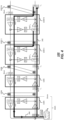
- FIG. 2 illustrates one scenario for operating the system 100 of FIG. 1 , according to embodiments of the disclosure.
- a set of DAS signals are launched from DAS stations 102A and DAS station 102B.
- FIG. 2 in particular shows in bold lines, the system optical signal flow for outbound and inbound fibers to perform DAS sensing of the shore spans, meaning the spans 120A and spans 120D, which spans may lie within 100 km of the opposing shores, represented by DAS station 102A and DAS station 102B.
- the DAS station 102A launches a first DAS signal 202 from a first IU at a first interrogation rate and wavelength ⁇ 1 , for which an exemplary set of parameters may be specified from Table I.
- This wavelength may be used to probe acoustic disturbances over a range of 100 km from shore, for example. Since the sensing range is 100 km, according to different embodiments, this segment can be divided into one (100-km-repeater spacing) or two (50-km repeater-spacing) sensing spans.
- the loopback associated with repeaters 130A may generally represent one or two different loopbacks in different embodiments.
- the loopback associated with repeaters 130A (including circulator, EDFA and filter or OADM) is needed just for one direction (i.e., inbound to the closest shore, represented by DAS station 102A), to provide a return DAS signal 204 that provides DAS information from a sensing range within 100 km of shore.
- the system cost of system 100 is lowered with respect to systems that may require bi-directional loopbacks in a given repeater, each requiring a circulator, EDFA and filter or OADM.
- the DAS station 102B may function similarly to DAS station 102A to launch a second DAS signal 212 and monitor a return signal 214 in order to probe DAS information from a sensing range of 100 km from the shore of DAS station 102B.
- the wavelength and interrogation rate for second DAS signal 212 may (but need not) be the same as the wavelength and interrogation rate of first DAS signal 202, thus lowering system complexity.
- the sensing wavelength of the given outbound DAS signal (first DAS signal 202 or second DAS signal 212) may be blocked from the outbound fiber of the system 100 at the end of 100 km span length in order to boost the power of the remaining sensing wavelengths and prevent interference at the opposite end.
- the first DAS signal 202 is dropped at the furthest loopback from DAS station 102A of loopbacks associated with repeaters 130A, and the second DAS signal 212 is blocked at the furthest loopback from DAS station 102B of the loopbacks associated with the repeaters 130B.
- FIG. 3 illustrates another scenario for operating the DAS system of FIG. 1 , according to embodiments of the disclosure. Only the west part of the system is shown. The eastern part behaves in a similar manner. In this case, another set of DAS signals are launched from DAS station 102A.
- FIG. 3 in particular shows the system optical signal flow through outbound and inbound fibers for performing DAS sensing of the intermediate spans, meaning the spans 120C and spans 120D (see also FIG. 1 ), which spans may lie for example, between 100 km to 500 km from the shore of the DAS station 102A or DAS station 102B, respectively.
- the DAS station 102A launches another DAS signal, shown as DAS signal 222, from a second IU at a second interrogation rate and wavelength ⁇ 2, for which an exemplary set of parameters may be specified from Table I.
- This wavelength will differ from ⁇ 1 and may be used to probe acoustic disturbances over a range of 100 km to 500 km from shore, for example.
- the interrogation rate of the DAS signal 222 will be less than the interrogation rate of first DAS signal 202, as shown in table 1, e.g., 200 Hz, with a maximum sensing frequency of 100 Hz.
- loopback ⁇ 130C 1' to ⁇ 130C N' each loopback of which may coincide with a corresponding repeater, and may be separated from one another by a span 120B 1 - 120B N
- the loopbacks within the 130C-loopback array can be divided into 4 (100-km-repeater spacing) to 8 (50-km-repeater spacing) sensing spans.
- an individual loopback of loopback within the 130 loopback array may be unidirectional (including circulator, EDFA and filter or OADM) since these spans are meant to be covered just by DAS station 102A and thus, loopback is again needed for just one direction (i.e., return direction to the shore of DAS station 102A), thus lowering the system cost.
- the return DAS signal 224 routed back to the DAS station 102A, may be divided into a series of return signals that are routed through a series of loopbacks of the 130C-loopback array. These return signals are shown as DAS signal ⁇ 224 A' to DAS signal ⁇ 224 N', and are routed through loopbacks ⁇ 130C 1' to loopback ⁇ 130C N', respectively.
- the region associated with multiple spans covering a distance of 100 km to 500 km from shore can be measured with a single outbound DAS IU wavelength, ⁇ 2.
- DAS signal 222 needs to be much smaller than the pulse travelling time in the shortest span and the pulse period is larger than the sum of the pulse width and the pulse travelling time in the longest span.
- FIG. 4 illustrates a further scenario for operating the system 100 of FIG. 1 , according to embodiments of the disclosure. Only the west part of the system is shown. The eastern part behaves in a similar manner. In this scenario the optical signal flow for sensing in the deep ocean environment is depicted. As such, a set of loopbacks are depicted, corresponding to the loopbacks associated with remote repeaters 130E, discussed above. In particular, a loopback 130E1 and loopback 130EN are depicted, where loopbacks may represent loopbacks arranged at opposite ends of the spans associated with a first repeater 130E 1 and a last repeater 130E N of the remote repeaters 130E, for purposes of illustration. As noted, the sensing range covered by this set of loopbacks may be up to 9,000 km.
- DAS station 102A launches another DAS signal, shown as DAS signal 242, from a third IU at a third interrogation rate and wavelength ⁇ 3, for which an exemplary set of parameters may be selected from Table I.
- This wavelength will differ from ⁇ 1 and ⁇ 2 and may be used to probe acoustic disturbances over a range of 500 km from shore of DAS station 102A to 500 km from DAS station 102B.
- the link between DAS station 102A and DAS station 102B spans exactly 10,000 km, for example, the range of spans associated with repeater130E 1 to repeater 130E N may cover 9,000 km as an example.
- the interrogation rate of a return signal 244 derived from the DAS signal 242 will be less than the interrogation rate of first DAS signal 202, and DAS signal 222, as shown in table 1, e.g., 10 Hz, and the maximum sensing frequency is ⁇ 5 Hz.
- this group of spans may be divided into 90 (100-km -repeater spacing) to 180 (50-km-repeater spacing) sensing spans.
- the sensing wavelength of the DAS signal 242 ( ⁇ 3) can be blocked from the outbound fiber of the system at the end of 9500 km (furthest of spans 120 from DAS station 102A, such as at loopback'120C N') to boost the inbound (return) loopback signals from the opposite direction.
- the sensing wavelength of DAS signal 242 may be retained in the system 100, in the final 500 km (Spans closest to DAS station 102B), since this retention may not unduly affect the inbound loopback signals from the opposite direction.
- a method is suggested to significantly improve the measurement sensing sensitivity, due to the loopbacks being provided for both directions for the spans 120C.
- the sensitivity can be improved by 20 dB (assuming 0.2dB/km fiber loss).
- DSP digital signal processing
- a digital signal processing (DSP) analysis algorithm for analysis of the returned DAS signals may be designed to process just the data from the first half of each span (from the EDFA output).
- the DAS IU sensing capability for a particular span of the spans 120 may cover just the first 50 km for a 100 km span, depending on the DAS IU capabilities.
- the system span length can be 50 km for the distance from 0 - 500 km, and the span length for the remaining part of the system (from 500 km to 9500 km) can be doubled to 100 km.
- each 100 km-length span in the range of 500 km-9500 km can be interrogated in two parts, a 50 km part by DAS IU in DAS station 102A, and a second 50 km part by DAS IU in DAS station 102B.
- repeaters 130E include 90 loopbacks over 9,000 km
- the repeaters 130A-130D collectively include 20 more loopbacks to cover the nearest 500 km from each shore at 50 km span intervals.
- a DAS sensing system may be designed to have multiple numbers of sensing channels (DAS IU wavelengths) from each end. Each channel may cover a different distance in the DAS system, with an optimized interrogation rate and sensing frequency range.
- DAS IU wavelengths may cover a different distance in the DAS system, with an optimized interrogation rate and sensing frequency range.
- Launching of different DAS IU signals can in addition be time-synchronized and staggered by wavelengths for launching and detection using the synchronization techniques to facilitate proper detection of the different signals.
- a link may be divided into just two types of spans.
- near shore spans may be probed using loopbacks arranged to direct detection of signals generated by a first IU at a first wavelength and interrogation rate
- intermediate spans may be probed using loopbacks arranged to direct detection of signals generated by a second IU at a second wavelength and second interrogation rate.
- a first set of intermediate spans associated with the first station may not overlap with a second set of intermediate spans associated with the second station, such that each DAS IU in the two DAS station probes just the first half of the link closest to that station.
- FIG. 5 presents an exemplary process flow 500.
- the operation is performed of launching a first DAS signal from a first DAS IU in a first DAS station at a first interrogation rate and first wavelength.
- the operation is performed of launching a second DAS signal from a second DAS IU in DAS station at a second wavelength, different than the first wavelength, and second interrogation rate, less than first interrogation rate.
- the operation is performed of launching a third DAS signal from a third DAS IU in the DAS station at a third interrogation rate, less than second interrogation rate and at a third wavelength, different from the first wavelength and the second wavelength.
- the operation is performed of routing back the first DAS signal to the DAS station through a particular loopback or a set of proximate loopbacks nearest to the DAS station.
- the operation is performed of routing back the second DAS signal to the DAS station through a particular loopback or a set of intermediate loopbacks, located further from the DAS station.
- the operation is performed of routing back the third DAS signal to the DAS station through a particular loopback or a set of distant loopbacks, located further from the DAS station than the set of intermediate loopbacks.
Landscapes
- Physics & Mathematics (AREA)
- General Physics & Mathematics (AREA)
- Electromagnetism (AREA)
- Engineering & Computer Science (AREA)
- Computer Networks & Wireless Communication (AREA)
- Signal Processing (AREA)
- Optical Communication System (AREA)
- Optical Transform (AREA)
Applications Claiming Priority (1)
| Application Number | Priority Date | Filing Date | Title |
|---|---|---|---|
| US18/498,231 US20250137838A1 (en) | 2023-10-31 | 2023-10-31 | Multi-span distributed acoustic sensing from the shore with different sensing frequency ranges and sensing span lengths |
Publications (1)
| Publication Number | Publication Date |
|---|---|
| EP4549890A1 true EP4549890A1 (fr) | 2025-05-07 |
Family
ID=93291700
Family Applications (1)
| Application Number | Title | Priority Date | Filing Date |
|---|---|---|---|
| EP24209130.4A Pending EP4549890A1 (fr) | 2023-10-31 | 2024-10-28 | Détection acoustique distribuée à portées multiples à partir du rivage avec différentes plages de fréquences de détection et longueurs de portée de détection |
Country Status (4)
| Country | Link |
|---|---|
| US (1) | US20250137838A1 (fr) |
| EP (1) | EP4549890A1 (fr) |
| JP (1) | JP2025076334A (fr) |
| CN (1) | CN119915373A (fr) |
Citations (4)
| Publication number | Priority date | Publication date | Assignee | Title |
|---|---|---|---|---|
| US20160169768A1 (en) * | 2010-11-11 | 2016-06-16 | Fotech Solutions Limited | Distributed Optical Fibre Sensor |
| US20220397448A1 (en) * | 2021-06-15 | 2022-12-15 | Subcom, Llc | Extending dynamic acoustic sensing range and localization in undersea cables using loopbacks |
| US20230095884A1 (en) * | 2021-09-30 | 2023-03-30 | Halliburton Energy Services, Inc. | Detecting out-of-band signals in a wellbore using distributed acoustic sensing |
| EP4160941A1 (fr) * | 2021-09-29 | 2023-04-05 | Alcatel Submarine Networks | Détection et surveillance distribuées utilisant des liaisons optiques amplifiées |
Family Cites Families (3)
| Publication number | Priority date | Publication date | Assignee | Title |
|---|---|---|---|---|
| WO2018156132A1 (fr) * | 2017-02-23 | 2018-08-30 | Halliburton Energy Services, Inc. | Système de détection acoustique distribué équipé d'un dispositif de commande de polarisation destiné à améliorer le rapport signal sur bruit |
| US10727815B2 (en) * | 2018-12-06 | 2020-07-28 | Texas Instruments Incorporated | Methods and apparatus to measure resonant sensors based on detection of group delay |
| US12203892B1 (en) * | 2021-09-24 | 2025-01-21 | Triad National Security, Llc | Detection and monitoring of cracks and fractures using nonlinear response to multimode acoustic signals |
-
2023
- 2023-10-31 US US18/498,231 patent/US20250137838A1/en active Pending
-
2024
- 2024-10-18 JP JP2024182307A patent/JP2025076334A/ja active Pending
- 2024-10-28 EP EP24209130.4A patent/EP4549890A1/fr active Pending
- 2024-10-31 CN CN202411538339.7A patent/CN119915373A/zh active Pending
Patent Citations (4)
| Publication number | Priority date | Publication date | Assignee | Title |
|---|---|---|---|---|
| US20160169768A1 (en) * | 2010-11-11 | 2016-06-16 | Fotech Solutions Limited | Distributed Optical Fibre Sensor |
| US20220397448A1 (en) * | 2021-06-15 | 2022-12-15 | Subcom, Llc | Extending dynamic acoustic sensing range and localization in undersea cables using loopbacks |
| EP4160941A1 (fr) * | 2021-09-29 | 2023-04-05 | Alcatel Submarine Networks | Détection et surveillance distribuées utilisant des liaisons optiques amplifiées |
| US20230095884A1 (en) * | 2021-09-30 | 2023-03-30 | Halliburton Energy Services, Inc. | Detecting out-of-band signals in a wellbore using distributed acoustic sensing |
Also Published As
| Publication number | Publication date |
|---|---|
| CN119915373A (zh) | 2025-05-02 |
| JP2025076334A (ja) | 2025-05-15 |
| US20250137838A1 (en) | 2025-05-01 |
Similar Documents
| Publication | Publication Date | Title |
|---|---|---|
| US12111204B2 (en) | Extending dynamic acoustic sensing range and localization in undersea cables using loopbacks | |
| CN111181631B (zh) | 一种基于时分空分复用的有中继海底光缆扰动监测系统 | |
| US11668590B2 (en) | System and method for fiber sensing | |
| EP2088697B1 (fr) | Système et procédé d'identification de défauts dans des systèmes de communication optique | |
| US5790294A (en) | Line monitoring method and line monitoring apparatus | |
| US12360005B2 (en) | Extending DAS range in undersea cables using loopbacks | |
| US6842586B2 (en) | OTDR arrangement for detecting faults in an optical transmission system employing two pairs of unidirectional optical fibers | |
| CN110492927B (zh) | 一种基于岸基探测的有中继海底光缆扰动监测系统 | |
| CN110518971B (zh) | 一种基于水下采样的有中继海底光缆扰动监测系统 | |
| US12332394B2 (en) | Fiber sensing using supervisory path of submarine cables | |
| EP4549890A1 (fr) | Détection acoustique distribuée à portées multiples à partir du rivage avec différentes plages de fréquences de détection et longueurs de portée de détection | |
| CN110932775B (zh) | 一种两路相位差回传信号的有中继海底光缆扰动监测系统 | |
| US12571673B2 (en) | Multi-span optical fiber das system with amplified-filtered loopback (AFLB) | |
| CN210670077U (zh) | 一种两路相位差回传信号的有中继海底光缆扰动监测系统 | |
| US7471895B2 (en) | Method and apparatus for obtaining status information concerning optical amplifiers located along an undersea optical transmission line using COTDR | |
| CN210867701U (zh) | 一种基于水下采样的有中继海底光缆扰动监测系统 | |
| CN210670076U (zh) | 一种基于时分空分复用的有中继海底光缆扰动监测系统 | |
| CN210518332U (zh) | 一种基于岸基探测的有中继海底光缆扰动监测系统 | |
| US20230060104A1 (en) | Fault detection apparatus, fault detection method, and submarine cable system | |
| US20180006733A1 (en) | Subsea long-haul transponder | |
| US20240297712A1 (en) | Environmental Change Detection | |
| JP2003115801A (ja) | 光伝送システムの安全化方法、同方法を実施するための装置、およびそのような装置を内蔵する光伝送システム | |
| US20250286623A1 (en) | DYNAMIC SEGMENTED DFOS OPERATION ON BIDIRECTIONAL WDM MULTI-SPAN FIBER LINKS USING FIBER NETWORK ROADMs | |
| HK1161448B (en) | Fault locator for long haul transmission system | |
| HK1161448A1 (en) | Fault locator for long haul transmission system |
Legal Events
| Date | Code | Title | Description |
|---|---|---|---|
| PUAI | Public reference made under article 153(3) epc to a published international application that has entered the european phase |
Free format text: ORIGINAL CODE: 0009012 |
|
| STAA | Information on the status of an ep patent application or granted ep patent |
Free format text: STATUS: THE APPLICATION HAS BEEN PUBLISHED |
|
| AK | Designated contracting states |
Kind code of ref document: A1 Designated state(s): AL AT BE BG CH CY CZ DE DK EE ES FI FR GB GR HR HU IE IS IT LI LT LU LV MC ME MK MT NL NO PL PT RO RS SE SI SK SM TR |
|
| STAA | Information on the status of an ep patent application or granted ep patent |
Free format text: STATUS: REQUEST FOR EXAMINATION WAS MADE |
|
| 17P | Request for examination filed |
Effective date: 20251105 |
|
| STAA | Information on the status of an ep patent application or granted ep patent |
Free format text: STATUS: EXAMINATION IS IN PROGRESS |
|
| 17Q | First examination report despatched |
Effective date: 20260116 |