EP4549989A1 - Annulation d'interférence de convertisseur analogique-numérique par filtre temporel - Google Patents
Annulation d'interférence de convertisseur analogique-numérique par filtre temporel Download PDFInfo
- Publication number
- EP4549989A1 EP4549989A1 EP23206794.2A EP23206794A EP4549989A1 EP 4549989 A1 EP4549989 A1 EP 4549989A1 EP 23206794 A EP23206794 A EP 23206794A EP 4549989 A1 EP4549989 A1 EP 4549989A1
- Authority
- EP
- European Patent Office
- Prior art keywords
- power
- radar
- adc
- sample
- samples
- Prior art date
- Legal status (The legal status is an assumption and is not a legal conclusion. Google has not performed a legal analysis and makes no representation as to the accuracy of the status listed.)
- Pending
Links
Images




Classifications
-
- G—PHYSICS
- G01—MEASURING; TESTING
- G01S—RADIO DIRECTION-FINDING; RADIO NAVIGATION; DETERMINING DISTANCE OR VELOCITY BY USE OF RADIO WAVES; LOCATING OR PRESENCE-DETECTING BY USE OF THE REFLECTION OR RERADIATION OF RADIO WAVES; ANALOGOUS ARRANGEMENTS USING OTHER WAVES
- G01S7/00—Details of systems according to groups G01S13/00, G01S15/00, G01S17/00
- G01S7/02—Details of systems according to groups G01S13/00, G01S15/00, G01S17/00 of systems according to group G01S13/00
- G01S7/023—Interference mitigation, e.g. reducing or avoiding non-intentional interference with other HF-transmitters, base station transmitters for mobile communication or other radar systems, e.g. using electro-magnetic interference [EMI] reduction techniques
-
- G—PHYSICS
- G01—MEASURING; TESTING
- G01S—RADIO DIRECTION-FINDING; RADIO NAVIGATION; DETERMINING DISTANCE OR VELOCITY BY USE OF RADIO WAVES; LOCATING OR PRESENCE-DETECTING BY USE OF THE REFLECTION OR RERADIATION OF RADIO WAVES; ANALOGOUS ARRANGEMENTS USING OTHER WAVES
- G01S13/00—Systems using the reflection or reradiation of radio waves, e.g. radar systems; Analogous systems using reflection or reradiation of waves whose nature or wavelength is irrelevant or unspecified
- G01S13/02—Systems using reflection of radio waves, e.g. primary radar systems; Analogous systems
- G01S13/06—Systems determining position data of a target
- G01S13/08—Systems for measuring distance only
- G01S13/32—Systems for measuring distance only using transmission of continuous waves, whether amplitude-, frequency-, or phase-modulated, or unmodulated
- G01S13/34—Systems for measuring distance only using transmission of continuous waves, whether amplitude-, frequency-, or phase-modulated, or unmodulated using transmission of continuous, frequency-modulated waves while heterodyning the received signal, or a signal derived therefrom, with a locally-generated signal related to the contemporaneously transmitted signal
- G01S13/343—Systems for measuring distance only using transmission of continuous waves, whether amplitude-, frequency-, or phase-modulated, or unmodulated using transmission of continuous, frequency-modulated waves while heterodyning the received signal, or a signal derived therefrom, with a locally-generated signal related to the contemporaneously transmitted signal using sawtooth modulation
-
- G—PHYSICS
- G01—MEASURING; TESTING
- G01S—RADIO DIRECTION-FINDING; RADIO NAVIGATION; DETERMINING DISTANCE OR VELOCITY BY USE OF RADIO WAVES; LOCATING OR PRESENCE-DETECTING BY USE OF THE REFLECTION OR RERADIATION OF RADIO WAVES; ANALOGOUS ARRANGEMENTS USING OTHER WAVES
- G01S7/00—Details of systems according to groups G01S13/00, G01S15/00, G01S17/00
- G01S7/02—Details of systems according to groups G01S13/00, G01S15/00, G01S17/00 of systems according to group G01S13/00
- G01S7/35—Details of non-pulse systems
- G01S7/352—Receivers
- G01S7/354—Extracting wanted echo-signals
-
- G—PHYSICS
- G01—MEASURING; TESTING
- G01S—RADIO DIRECTION-FINDING; RADIO NAVIGATION; DETERMINING DISTANCE OR VELOCITY BY USE OF RADIO WAVES; LOCATING OR PRESENCE-DETECTING BY USE OF THE REFLECTION OR RERADIATION OF RADIO WAVES; ANALOGOUS ARRANGEMENTS USING OTHER WAVES
- G01S13/00—Systems using the reflection or reradiation of radio waves, e.g. radar systems; Analogous systems using reflection or reradiation of waves whose nature or wavelength is irrelevant or unspecified
- G01S13/02—Systems using reflection of radio waves, e.g. primary radar systems; Analogous systems
- G01S13/06—Systems determining position data of a target
- G01S13/42—Simultaneous measurement of distance and other co-ordinates
-
- G—PHYSICS
- G01—MEASURING; TESTING
- G01S—RADIO DIRECTION-FINDING; RADIO NAVIGATION; DETERMINING DISTANCE OR VELOCITY BY USE OF RADIO WAVES; LOCATING OR PRESENCE-DETECTING BY USE OF THE REFLECTION OR RERADIATION OF RADIO WAVES; ANALOGOUS ARRANGEMENTS USING OTHER WAVES
- G01S13/00—Systems using the reflection or reradiation of radio waves, e.g. radar systems; Analogous systems using reflection or reradiation of waves whose nature or wavelength is irrelevant or unspecified
- G01S13/02—Systems using reflection of radio waves, e.g. primary radar systems; Analogous systems
- G01S13/50—Systems of measurement based on relative movement of target
- G01S13/58—Velocity or trajectory determination systems; Sense-of-movement determination systems
- G01S13/583—Velocity or trajectory determination systems; Sense-of-movement determination systems using transmission of continuous unmodulated waves, amplitude-, frequency-, or phase-modulated waves and based upon the Doppler effect resulting from movement of targets
- G01S13/584—Velocity or trajectory determination systems; Sense-of-movement determination systems using transmission of continuous unmodulated waves, amplitude-, frequency-, or phase-modulated waves and based upon the Doppler effect resulting from movement of targets adapted for simultaneous range and velocity measurements
-
- G—PHYSICS
- G01—MEASURING; TESTING
- G01S—RADIO DIRECTION-FINDING; RADIO NAVIGATION; DETERMINING DISTANCE OR VELOCITY BY USE OF RADIO WAVES; LOCATING OR PRESENCE-DETECTING BY USE OF THE REFLECTION OR RERADIATION OF RADIO WAVES; ANALOGOUS ARRANGEMENTS USING OTHER WAVES
- G01S13/00—Systems using the reflection or reradiation of radio waves, e.g. radar systems; Analogous systems using reflection or reradiation of waves whose nature or wavelength is irrelevant or unspecified
- G01S13/88—Radar or analogous systems specially adapted for specific applications
- G01S13/93—Radar or analogous systems specially adapted for specific applications for anti-collision purposes
- G01S13/931—Radar or analogous systems specially adapted for specific applications for anti-collision purposes of land vehicles
Definitions
- Radar sensors are conventionally used in connection with detecting and classifying objects in an environment; advantages of radar over other types of sensors include robustness in regard to lighting and weather conditions.
- radar sensors are deployed with cameras and/or lidar sensors to provide different modes of detection and redundancy.
- performance of lidar and/or cameras is negatively impacted by environmental features, such as fog, rain, snow, bright sunlight, lack of adequate light, etc. Accordingly, in these scenarios, radar is relied heavily upon to detect and classify objects in the environment, while lidar and camera sensors are less heavily relied upon.
- a radar sensor generates a radar tensor, and the radar tensor is processed to detect and classify objects in the environment.
- the radar tensor includes power measurements generated by the radar sensor along different dimensions, such as Doppler, range, azimuth, and elevation.
- the radar tensor is then further processed to detect, classify, and track objects in the scene over time.
- radar sensor systems increase in popularity and are included in more and more vehicles, accurate tracking of moving objects becomes ever more important. False-positive detections are problematic, and at the same time, real objects need to be accurately and reliably detected and tracked.
- an autonomous vehicle perceives objects surrounding the autonomous vehicle based upon sensor signals generated by sensor systems of the autonomous vehicle.
- the autonomous vehicle may include a sensor system, such as a radar sensor system, for generating sensor signals.
- the autonomous vehicle also includes a centralized processing device that receives data based upon sensor signals generated by the sensor system and performs a variety of different tasks, such as detection of vehicles, pedestrians, and other objects. Based on an output of the processing device, the autonomous vehicle may perform a driving maneuver.
- Radar sensor systems exhibit some advantages over other sensor systems such as lidar sensor systems and cameras with respect to their usage in autonomous vehicles. For instance, performance of radar sensor systems is more invariant to weather changes, such that data generated by a radar sensor system can be used to enable autonomous driving under certain weather conditions (such as heavy rain or snow). In addition, radar sensor systems are able to capture velocity information nearly instantaneously.
- Radar sensor systems emit radar signals into a surrounding environment.
- the radar sensor signals reflect off objects in the environment and the radar sensor system then detects the reflected radar signals.
- the radar sensor system is configured to construct data tensors based upon the reflected radar signals, where a data tensor has bins across several dimensions. Example dimensions include range, doppler, and beam.
- the radar sensor system then generates point clouds based upon the data tensors and transmits the point clouds to the centralized processing device, where the centralized processing device identifies objects in the environment of the autonomous vehicle based upon the point clouds.
- Range resolution of a radar sensor system is a function of the bandwidth of a radar signal transmitted by the radar sensor system. All else being equal, employing a wider bandwidth radar signal to be transmitted by the radar sensor system generally provides a finer range resolution (as compared to range resolution provided by a radar sensor system that utilizes a narrower bandwidth radar signal). In various applications, such as radar sensor systems of vehicles (e.g., autonomous vehicles), it is desired to have relatively fine range resolution; thus, such systems commonly employ relatively wide bandwidth radar signals.
- vehicles e.g., autonomous vehicles
- a first radar sensor When multiple radar sensor systems are operating in the same environment, it is possible for a first radar sensor to receive a radar signal transmitted by a second radar sensor in addition to the first radar sensor's own radar signal.
- the second radar sensor's radar signal interferes with the first radar sensor's radar signal, resulting in a larger than expected power reading that can cause a false detection.
- Described herein are various technologies relating to radar sensor systems, and more specifically, radar sensor systems employed in autonomous vehicles, aircrafts, watercrafts, and the like. With more particularity, various technologies described herein facilitate mitigating interference in a radar sensor system by identifying and compensating for radar signal samples that have been affected by interference.
- a received radar signal is sampled by an analog-to-digital converter (ADC).
- ADC analog-to-digital converter
- the samples are analyzed to identify samples affected by interference (e.g., caused by a radar signal from another radar sensor system, etc.).
- the identified samples are then removed or adjusted before processing the radar signal, thereby preventing the interference from being spread throughout the radar spectrum and compromising the noise level and the false detection rate.
- the described technique is implemented after the ADC sampling stage, in the raw signal.
- Samples affected by interference can compromise the performance of the radar sensor system and have a much higher signal magnitude than the rest of the signal samples.
- the mean power variance of each frame's ADC signal is calculated.
- Signal samples having a power magnitude much greater (i.e., above a predetermined power threshold) than the mean power variance of the frame in which the sample is taken are removed or adjusted.
- a power threshold based on the mean power variance for the frame can be employed to mitigate loss of radar performance.
- Using signal variance instead of absolute magnitude to filter affected samples from the signal mitigates the problem of inadvertently filtering out samples compromised by saturation or reflections from close and/or strong targets.
- the received radar signal is sampled by an ADC, and each sample's power magnitude is acquired.
- Mean ADC sample power is calculated for each ramp in the signal by averaging the power magnitudes of the samples in the ramp.
- Mean power variance is calculated on a ramp-by-ramp basis or a frame-by-frame basis.
- the mean power variance can be calculated as the average of the absolute values of the difference between the absolute value of each ADC sample power magnitude and the mean ADC sample power.
- the real value or the squared value of each ADC sample magnitude can be used. Samples having a power magnitude greater than a power threshold are identified as having been subjected to interference.
- the power threshold can be a multiple of the calculated mean power variance (e.g., 1.5x, 2x, 2.5x, 3x, 4x, etc., the mean power variance).
- the power magnitudes of the identified samples are adjusted to mitigate the effect of the interference. For example, the power magnitude of an identified sample can be multiplied by zero to negate the interference effect of the identified sample prior to point cloud processing. In this manner, interference mitigation is performed on the raw radar data to mitigate the effects of samples that have been subjected to interference (e.g., caused by interfering radar signals from another radar sensor system or the like).
- the term "or” is intended to mean an inclusive “or” rather than an exclusive “or.” That is, unless specified otherwise, or clear from the context, the phrase “X employs A or B” is intended to mean any of the natural inclusive permutations. That is, the phrase “X employs A or B” is satisfied by any of the following instances: X employs A; X employs B; or X employs both A and B.
- the articles “a” and “an” as used in this application and the appended claims should generally be construed to mean “one or more” unless specified otherwise or clear from the context to be directed to a singular form.
- the terms “component” and “system” are intended to encompass computer-readable data storage that is configured with computer-executable instructions that cause certain functionality to be performed when executed by a processor.
- the computer-executable instructions may include a routine, a function, or the like. It is also to be understood that a component or system may be localized on a single device or distributed across several devices.
- the term "exemplary” is intended to mean serving as an illustration or example of something and is not intended to indicate a preference.
- Interference between radars is a problem in the autonomous driving sector. Interference can significantly affect the performance of a radar sensor system, especially the false positive and false negative rate. For example, interference can cause false detections or increase the noise level causing the radar sensor system to miss real detections. Interference between frequency modulated continuous wave (FMCW) radar sensor systems that do not have the same ramp slope or pulse repetition interval (PRI) usually occurs in just a few samples of the signal (in the short part of the time during the transmission of a frame). However, when this interference occurs in a direct line at short distances, even just a few samples that suffer interference can have a large impact on the performance of the radar sensor system. The radar sensor system's signal processing can cause the few interference-compromised samples to be scattered throughout the radar spectrum, which in turn causes the noise level to increase considerably, thereby decreasing the maximum detection range and potentially generating an increase in false detections.
- FMCW frequency modulated continuous wave
- PRI pulse repetition interval
- interference can be caused when two FMCW radar sensor systems transmit concurrently in the same bandwidth. This type of interference can affect relatively few samples of a signal received in a radar return. By filtering out the affected samples, the interference effect can be mitigated.
- interference-compromised signal samples are identified and removed prior to signal processing.
- a low-cost, efficient processing technique is provided that analyzes the power variance of the analog-to-digital conversion (ADC) signal to identify time samples having a power magnitude greater than the average variance of the signal in a radar frame. Identified samples can be removed, adjusted, or have their power attenuated to mitigate the interference effect.
- ADC analog-to-digital conversion
- the radar sensor 100 includes a transmit antenna 102, a receive antenna 104, and a hardware logic component 106.
- the hardware logic component 106 is configured to prepare radar signals that are transmitted by the transmit antenna 102, and to compute target solutions indicating estimated positions and/or velocities of objects based upon radar returns and/or other radar signals received by the receive antenna 104.
- various components of the radar sensor 100 can be integrated as a same system-on-a-chip (SoC).
- SoC system-on-a-chip
- the radar sensor 100 can be employed on a vehicle, such as a land vehicle, an aircraft, to identify positions and velocities of objects in the operational environment of the vehicle.
- the radar sensor 100 further comprises one or more DACs 108.
- the hardware logic component 106 comprises a signal generator component 110 that prepares radar signals for transmission by way of the transmit antenna 102.
- the signal generator component 110 is configured to control the DAC 108 to cause the DAC 108 to generate an analog radar signal for transmission by the transmit antenna 102.
- the signal generator component 110 generates digital values that, when received by the DAC 108, cause the DAC 108 to output an analog radar signal having various desired signal characteristics.
- the radar sensor 100 is configured as a digitally modulated radar sensor, wherein characteristics of radar signals output by the transmit antenna 102 are digitally controlled by the signal generator component 110 of the hardware logic component 106.
- the signal generator component 110 can be configured to control the DAC 108 such that the radar sensor operates as a frequency modulated continuous wave (FMCW) radar sensor, etc.
- FMCW frequency modulated continuous wave
- the radar sensor 100 further includes an analog signal processing component 112.
- the signal processing component 112 is generally configured to perform various analog signal processing operations on analog signals that are to be output by the transmit antenna 102 and/or that are received by the receive antenna 104.
- the signal processing component 112 can amplify a radar signal output by the DAC 108 to increase the power of the radar signal prior to transmission by way of the transmit antenna 102.
- the signal processing component 112 can be configured to mix a radar signal output by the DAC 108 with a carrier signal to shift a center frequency of the radar signal.
- the signal processing component 112 can include any of various components that are configured to perform these various functions.
- the signal processing component 112 can include mixers, amplifiers, filters, or the like. Functionality of the signal processing component 112 and its constituent components can be controlled by the hardware logic component 106.
- the transmit antenna 102 receives processed radar signals from the signal processing component 112 and emits the radar signals into an operational environment of the radar sensor 100.
- the receive antenna 104 receives radar returns from the operational environment.
- the radar returns received by the receive antenna 104 comprise reflections, from objects in the operational environment of the sensor 100, of radar signals emitted by the transmit antenna 102. It is to be understood that the radar returns received by the receive antenna 104 can further include reflections of radar signals emitted by other radar emitters that are active within the operational environment of the radar sensor 100. Responsive to receipt of radar returns from the operational environment of the sensor 100, the receive antenna 104 outputs an electrical signal that is indicative of the received radar returns.
- This electrical signal is referred to herein as a radar signal and is transmitted along one or more transmission lines in the radar sensor 100, as distinct from radar returns that are received by the receive antenna 104 as radiated signals propagating through air or free space in the operational environment of the radar sensor 100.
- the signal processing component 112 receives a radar signal from the receive antenna 104.
- the signal processing component 112 is configured to perform various analog signal processing operations over radar signals received from the receive antenna 104.
- the signal processing component 112 can perform various mixing, filtering, and amplification operations on radar signals output by the receive antenna 104.
- the signal processing component 112 can be configured to perform various of these signal processing operations (e.g., mixing) based further upon a radar signal transmitted by the transmit antenna 102.
- the radar sensor 100 further comprises one or more ADCs 114 that receives a processed radar signal from the signal processing component 112.
- the ADC 114 digitally samples the radar signal and outputs digital values that are indicative of amplitude of the radar signal over time. These digital values are collectively referred to herein as radar data.
- the radar data output by the ADC 114 are indicative of the radar returns received by the receive antenna 104.
- the hardware logic component 106 receives the radar data from the ADC 114.
- the hardware logic component 106 further comprises a radar processing component 116.
- the radar processing component 116 is configured to compute positions and/or velocities of targets in the operational environment of the radar sensor 100 based upon the radar data.
- the radar processing component 116 can compute a range, a bearing, and/or a velocity of a target in the operational environment of the sensor 100 based upon the radar data.
- the hardware logic component 106 comprises the signal generator component 110 and the radar processing component 116, as discussed with regard to Fig. 1 .
- the signal generator component 110 comprises a processor 200 and a memory 202 configured to provide certain functionality as described herein.
- the memory 202 can store computer-executable instructions that, when executed by the processor 200, cause the signal generator component 110 to perform certain acts.
- the memory 202 comprises a ramp/pulse generator component 204 that generates ramps/pulses (depending on the type of radar sensor system) for transmission.
- the ramp/pulse generator component 204 performs time division multiplexing and/or frequency division multiplexing on the signals to be transmitted.
- the radar processing component 116 comprises a processor 206 and a memory 208 configured to provide certain functionality as described herein.
- the memory 208 can store computer executable instructions that, when executed by the processor 206, cause the radar processing component 116 to perform certain acts.
- the memory 208 further comprises an interference mitigation component 209 that adjusts ADC samples affected by interference.
- the interference mitigation component 209 calculates a mean power variance (e.g., standard deviation) for ADC samples on a frame-by-frame basis or a ramp-by-ramp basis.
- a power threshold is set (e.g., as a multiple of the calculated mean power variance, or some other desired threshold value), and ADC samples having a power magnitude above the power threshold are adjusted or removed.
- the adjustment comprises multiplying the identified sample's power magnitude by zero.
- the adjustment comprises attenuating the sample's power magnitude down to the mean power for the frame or ramp.
- the adjustment comprises removing the sample and reconstructing a replacement sample that has a power magnitude within the mean power variance for the frame or ramp.
- the interference mitigation component 209 receives from the ADC the power magnitude for each sample in a given ramp and calculates the mean sample power for the samples in the given ramp by averaging the absolute values of the samples' power magnitudes. The interference mitigation component 209 also calculates the mean power variance for the given ramp. Once the mean power variance for the given ramp has been calculated, the interference mitigation component 209 applies a power threshold that is based on the mean power variance to samples in the ramp.
- the power threshold can be, for example, a multiple of the calculated mean power variance for the ramp. Samples that exceed the power threshold can be adjusted, e.g., by having their power magnitude multiplied by zero or in another manner as described herein.
- the interference mitigation component 209 averages the mean power variances of some or all of the ramps in a given frame to generate a mean power variance for the frame. Sample power magnitudes are compared to a power threshold that is based on the mean power variance of a given frame, and outliers are adjusted as described herein.
- the memory 208 also comprises a range fast Fourier transform (FFT) component 210 that is executed on a digitized signal received from an ADC, such as the ADC 114 of Fig. 1 , after interference mitigation by the interference mitigation component 209 to generate range data values 212 for objects detected in a received radar return.
- a Doppler FFT 214 is executed on the range values to generate range and Doppler data values 216.
- a discrete Fourier transform (DFT) 218 is then executed on the range and Doppler data values to generate elevation and azimuth data values 220. It will be understood that the described approach is not limited to using a DFT, but rather can employ any suitable direction of arrival (DoA) technique.
- a point cloud estimation component 222 is executed to generate one or more multi-dimensional point clouds 224 representing at least the range data values 212, the range and Doppler data values 216, and the elevation and azimuth data values 220.
- Fig. 3 shows another example of a radar sensor unit 300.
- signal processing at the radar sensor terminates with generation of the point clouds, which are then transmitted to a central processing unit or computer where they are processed further.
- the sensor 300 comprises a signal generator 302 that provides a signal to a local oscillator 304.
- the local oscillator 304 adjusts the signal for transmission via one or more transmit antennas 306.
- the local oscillator 304 also provides the transmit signal to a mixer 308, which combines the transmit signal with signals that have been reflected by an object and received by one or more receive antennas 310.
- the combined signal is then provided by the mixer 308 to an ADC 312, which digitizes the combined signal and provides the digitized signal to a radar processing component 314.
- the radar processing unit 314 performs various acts on the digitized signal and provides functionality similar or identical to the functionality provided by the radar processing component 116 of the hardware logic component 106 (see, e.g., Figs. 1 and 2 ).
- the radar processing component 314 generates one or more multi-dimensional point clouds, which are then transmitted to a central processing unit 316 for additional processing.
- the central processing unit 316 performs the processing steps described with regard to the radar processing component 116 of Fig. 2 and/or executes the methods of Figs. 4-5 .
- the central processing unit 316 receives raw radar data from a radar sensor and processes the raw data, including interference mitigation, to generate point clouds and provide the functionality described herein.
- Fig. 4-5 illustrate exemplary methodologies relating to mitigating interference in raw radar signal data. While the methodologies are shown and described as being a series of acts that are performed in a sequence, it is to be understood and appreciated that the methodologies are not limited by the order of the sequence. For example, some acts can occur in a different order than is described herein. In addition, an act can occur concurrently with another act. Further, in some instances, not all acts may be required to implement a methodology described herein.
- the acts described herein may be computer-executable instructions that can be implemented by one or more processors and/or stored on a computer-readable medium or media.
- the computer-executable instructions can include a routine, a sub-routine, programs, a thread of execution, and/or the like.
- results of acts of the methodology can be stored in a computer-readable medium, displayed on a display device, and/or the like.
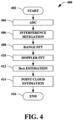
- a methodology 400 is illustrated for generating a radar point cloud.
- the method begins.
- analog to digital conversion is performed on signals received by the sensor. This step is performed for each array element (e.g., Tx/Rx pair) of the radar sensor.
- interference mitigation is performed as described herein with regard to various aspects (see, e.g., Figs. 2 and 5 , inter alia).
- a range fast Fourier transform is executed thereon to generate range data for the detected object.
- a Doppler FFT transform is executed on the range data in order to generate range and Doppler data.
- direction of arrival estimation is performed on the range and Doppler data to generate elevation and azimuth data.
- Direction of arrival estimation can be performed using, e.g., a beamforming technique, a discrete Fourier transform (DFT), or any other suitable technique.
- DFT discrete Fourier transform
- the range data, the range and Doppler data, and the elevation and azimuth data are used for point cloud estimation. The method terminates at 416.
- a methodology 500 is illustrated for mitigating interference in raw radar signal data.
- the method begins at 502.
- ADC samples of ramps in a radar signal frame are received or otherwise acquired.
- a power magnitude for each ADC sample is acquired.
- mean ADC sample power for the ADC samples in each ramp is calculated.
- mean power variance for each frame is calculated based on the mean sample powers of the ramps in the frame.
- samples having a power magnitude above a power threshold are identified.
- the power variance threshold may be, for example, a multiple of the mean power variance calculated for the frame, or some other desired value based on the mean power variance of the frame.
- power magnitudes of the identified samples are adjusted. The method terminates at 516.
- power magnitude adjustment includes multiplying the power magnitude value for the identified samples by zero. In another embodiment, power magnitude adjustment comprises attenuating the power magnitude of the identified samples. In yet another embodiment, power magnitude adjustment comprises removing the identified samples and replacing them with recreated sample values.
- the mean power variance is calculated for each ramp rather than each frame (i.e., a ramp-by-ramp basis), and the method proceeds accordingly with sample identification and power magnitude adjustment.
- Figs. 4 and 5 can be performed by any of the systems and/or components of Figs. 1-3 , 8-9 , etc.
- Fig. 6 illustrates a plurality of interfered ramps 602 and a non-interfered ramp 604.
- Interference between FMCW radar sensor systems that do not have the same ramp slope or PRI usually occurs in just a few samples of the signal (short part of the time during the transmission of a frame). However, when this interference occurs in a direct line at short distances, even a relatively few samples that suffer interference can deleteriously affect the performance of the radar sensor system.
- Interfering ramps 606 (e.g., from another radar sensor system) use the same frequency as the interfered ramps 602 where they cross the interfered ramps 602. During ADC sampling, samples taken at the crossing points will register a higher than expected power magnitude, as shown by the sample peaks 608. These samples can be identified and compensated using the techniques described herein.
- Fig. 7 illustrates a graphical representation 700 of power magnitude across ADC samples.
- the samples that suffer from interference can compromise the performance of the radar sensor system and have a much higher signal magnitude than the signal variance.
- the signal magnitude variance 702 of the frame's ADC signal is used to generate a power threshold that is applied to identify samples that have been subjected to interference. All signal samples with a magnitude much greater than the signal variance are removed or otherwise adjusted. Samples registering a power magnitude above the power threshold are removed (e.g., by multiplying the power magnitude by 0), or otherwise compensated, to avoid loss of radar performance.
- signal variance instead of absolute magnitude to filter the signal avoids the problem of inadvertently filtering out signals compromised by saturation or reflections from close/strong targets.
- the variance and the mean power of the whole frame are calculated, and only the samples with power levels above the power threshold are adjusted or removed.
- This threshold can be an absolute value or a ratio to estimated variance.
- the mean variance calculation is performed per ramp instead of per frame.
- AV 800 an exemplary AV 800 is illustrated, wherein the AV 800 can navigate about roadways without human conduction based upon sensor signals output by sensor systems of the AV 800.
- the AV 800 includes a plurality of sensor systems 802-808 (a first sensor system 802 through an Nth sensor system 808).
- the sensor systems 802-808 may be of different types.
- the first sensor system 802 is a radar sensor system
- the second sensor system 804 may be a LiDaR sensor system
- the third sensor system 806 may be a camera (image) system
- the Nth sensor system 808 may be a sonar system.
- Other exemplary sensor systems include GPS sensor systems, inertial sensor systems, infrared sensor systems, and the like.
- the various sensor systems 802-808 are arranged about the AV 800.
- the sensor systems 802-808 are configured to repeatedly (e.g., continuously, or periodically) output sensor data that is representative of objects and conditions in the driving environment of the AV 800.
- the AV 800 further includes several mechanical systems that are used to effectuate appropriate motion of the AV 800.
- the mechanical systems can include but are not limited to, a vehicle propulsion system 810, a braking system 812, and a steering system 814.
- the vehicle propulsion system 810 may be an electric engine, an internal combustion engine, or a combination thereof.
- the braking system 812 can include an engine brake, brake pads, actuators, a regenerative braking system, and/or any other suitable componentry that is configured to assist in decelerating the AV 800.
- the steering system 814 includes suitable componentry that is configured to control the direction of movement of the AV 800.
- the AV 800 additionally comprises a computing system 816 that is in communication with the sensor systems 802-808 and is further in communication with the vehicle propulsion system 810, the braking system 812, and the steering system 814.
- the computing system 816 includes a processor 818 and memory 820 that includes computer-executable instructions that are executed by the processor 818.
- the processor 818 can be or include a graphics processing unit (GPU), a plurality of GPUs, a central processing unit (CPU), a plurality of CPUs, an application-specific integrated circuit (ASIC), a microcontroller, a programmable logic controller (PLC), a field programmable gate array (FPGA), or the like.
- the memory 820 comprises a perception system 822, a planning system 824, and a control system 826.
- the perception system 822 is configured to identify the presence of objects and/or characteristics of objects in the driving environment of the AV 800 based upon sensor data output by the sensor systems 802-808.
- the planning system 824 is configured to plan a route and/or a maneuver of the AV 800 based upon data pertaining to objects in the driving environment that are output by the perception system 822.
- the control system 826 is configured to control the mechanical systems 812-814 of the AV 800 to effectuate appropriate motion to cause the AV 800 to execute a maneuver planned by the planning system 824.
- the perception system 822 is configured to identify objects in proximity to the AV 800 that are captured in sensor signals output by the sensor systems 802-808.
- the perception system 822 can be configured to identify the presence of an object in the driving environment of the AV 800 based upon images generated by a camera system included in the sensor systems 804-808.
- the perception system 822 can be configured to determine a presence and position of an object based upon radar data output by the radar sensor system 802.
- the radar sensor system 802 can be or include the radar sensor 100 and/or 300.
- the perception system 822 can be configured to identify a position of an object in the driving environment of the AV 800 based upon the estimated range output by the radar sensor 100 and/or 300.
- the AV 800 can be included in a fleet of AVs that are in communication with a common server computing system.
- the server computing system can control the fleet of AVs such that radar sensor systems of AVs operating in a same driving environment (e.g., within line of sight of one another, or within a threshold distance of one another) employ different pulse sequence carrier frequencies.
- a radar sensor system of a first AV can be controlled so as not to transmit pulse sequences having same center frequencies as pulse sequences transmitted by a radar sensor system of a second AV at the same time.
- the radar sensor system of the first AV can be controlled to transmit pulse sequences in a different order than a radar sensor system of a second AV.
- the radar sensor system of the first AV can be configured to transmit a set of pulse sequences at four different center frequencies A, B, C, and D in an order A, B, C, D.
- the radar sensor system of the second AV can be configured to transmit pulse sequences using a same set of center frequencies in a frequency order B, A, D, C.
- the computing device 900 may be or include the computing system 816.
- the computing device 900 includes at least one processor 902 that executes instructions that are stored in a memory 904.
- the instructions may be, for instance, instructions for implementing functionality described as being carried out by one or more modules, components, or systems discussed above or instructions for implementing one or more of the methods described above.
- the processor 902 may be a GPU, a plurality of GPUs, a CPU, a plurality of CPUs, a multi-core processor, a combination of the foregoing, etc.
- the processor 902 may access the memory 904 by way of a system bus 906.
- the memory 904 may also store radar data, beamformed radar data, neural network configurations, etc.
- the computing device 900 additionally includes a data store 908 that is accessible by the processor 902 by way of the system bus 906.
- the data store 908 may include executable instructions, radar data, beamformed radar data, embeddings of these data in latent spaces, etc.
- the computing device 900 also includes an input interface 910 that allows external devices to communicate with the computing device 900. For instance, the input interface 910 may be used to receive instructions from an external computing device, etc.
- the computing device 900 also includes an output interface 912 that interfaces the computing device 900 with one or more external devices. For example, the computing device 900 may transmit control signals to the vehicle propulsion system 810, the braking system 812, and/or the steering system 814 by way of the output interface 912.
- the computing device 900 may be a distributed system. Thus, for instance, several devices may be in communication by way of a network connection and may collectively perform tasks described as being performed by the computing device 900.
- Computer-readable media includes computer-readable storage media.
- a computer-readable storage media can be any available storage media that can be accessed by a computer.
- such computer-readable storage media can comprise RAM, ROM, EEPROM, CD-ROM or other optical disk storage, magnetic disk storage or other magnetic storage devices, or any other medium that can be used to store desired program code in the form of instructions or data structures and that can be accessed by a computer.
- Disk and disc include compact disc (CD), laser disc, optical disc, digital versatile disc (DVD), floppy disk, and Blu-ray disc (BD), where disks usually reproduce data magnetically and discs usually reproduce data optically with lasers. Further, a propagated signal is not included within the scope of computer-readable storage media.
- Computer-readable media also includes communication media including any medium that facilitates transfer of a computer program from one place to another. A connection, for instance, can be a communication medium.
- the software is transmitted from a website, server, or other remote source using a coaxial cable, fiber optic cable, twisted pair, digital subscriber line (DSL), or wireless technologies such as infrared, radio, and microwave
- coaxial cable, fiber optic cable, twisted pair, DSL, or wireless technologies such as infrared, radio and microwave
- the coaxial cable, fiber optic cable, twisted pair, DSL, or wireless technologies such as infrared, radio and microwave
- the functionally described herein can be performed, at least in part, by one or more hardware logic components.
- illustrative types of hardware logic components include FPGAs, ASICs, Application-specific Standard Products (ASSPs), SOCs, Complex Programmable Logic Devices (CPLDs), etc.
- a method performed by a radar sensor system includes receiving analog-to-digital converted (ADC) samples of a received radar signal. The method also includes identifying power magnitudes for the ADC samples. The method further includes calculating a mean power value for ADC samples in a given ramp of the received radar signal. Additionally, the method includes calculating a mean power variance of the ADC samples in the given ramp. Moreover, the method includes identifying an ADC sample having a power magnitude above a power threshold. The method also includes adjusting the power magnitude of the identified ADC sample.
- ADC analog-to-digital converted
- the power threshold is a multiple of the mean power variance.
- the radar signal comprises a plurality of ramps
- the method further includes, on a per-sample basis, calculating a difference between the absolute value of the power magnitude of a given ADC sample and the mean power magnitude for the ramp from which the given ADC sample was taken.
- the method also includes calculating the mean power variance by averaging the absolute values of the calculated differences.
- the radar signal comprises a plurality of frames comprising ramps
- the acts further include calculating the mean power variance by averaging the mean power variances of ramps in a given frame.
- adjusting the power magnitude of the identified sample comprises multiplying the identified sample power magnitude by zero.
- adjusting the power magnitude of the identified sample comprises attenuating the identified sample power magnitude to a level within the mean power variance for the ramp from which the identified sample was taken.
- the method further includes generating a point cloud using the ADC samples and the adjusted ADC sample.
- a radar system is configured to perform at least one of the methods disclosed herein (e.g., any of the methods of (A1)-(A7)).
- a radar system includes a hardware logic component (e.g., circuitry), where the hardware logic component is configured to control elements of a radar system to perform at least one of the methods disclosed herein (e.g., any of the methods of (A1)-(A7)).
- a hardware logic component e.g., circuitry
- the hardware logic component is configured to control elements of a radar system to perform at least one of the methods disclosed herein (e.g., any of the methods of (A1)-(A7)).
- a radar sensor system includes a receive antenna that receives a radar return; and circuitry configured to perform certain acts.
- the acts include receiving analog-to-digital converted (ADC) samples of a received radar signal.
- the acts also include identifying power magnitudes for the ADC samples.
- the acts further include calculating a mean power value for ADC samples in a given ramp of the received radar signal. Additionally, the acts include calculating a mean power variance of the ADC samples in the given ramp.
- the acts also include identifying a sample having a power magnitude above a power threshold.
- the acts further include adjusting the power magnitude of the identified sample.
- the power threshold is a multiple of the mean power variance.
- the radar signal comprises a plurality of ramps
- the acts further include, on a per-sample basis, calculating a difference between the absolute value of the power magnitude of a given ADC sample and the mean power magnitude for the ramp from which the given ADC sample was taken.
- the acts also include calculating the mean power variance by averaging the absolute values of the calculated differences.
- the radar signal comprises a plurality of frames comprising ramps
- the acts further include calculating the mean power variance by averaging the mean power variances of ramps in a given frame.
- adjusting the power magnitude of the identified sample comprises multiplying the identified sample power magnitude by zero.
- adjusting the power magnitude of the identified sample comprises attenuating the identified sample power magnitude to a level within the mean power variance for the ramp from which the identified sample was taken.
- the acts further include generating a point cloud using the ADC samples and the adjusted ADC sample.
- a hardware logic component includes one or more processors configured to perform certain acts, the acts including receiving analog-to-digital converted (ADC) samples of a received radar signal. The acts further include identifying power magnitudes for the ADC samples. The acts also include calculating a mean power value for ADC samples in a given ramp of the received radar signal. Additionally, the acts include calculating a mean power variance of the ADC samples in the given ramp. Moreover, the acts include identifying a sample having a power magnitude above a power threshold. The acts also include adjusting the power magnitude of the identified sample.
- ADC analog-to-digital converted
- the power threshold is a multiple of the mean power variance.
- the radar signal comprises a plurality of ramps
- the acts further include, on a per-sample basis, calculating a difference between the absolute value of the power magnitude of a given ADC sample and the mean power magnitude for the ramp from which the given ADC sample was taken.
- the acts also include calculating the mean power variance by averaging the absolute values of the calculated differences.
- radar signal comprises a plurality of frames comprising ramps, and the acts further include calculating the mean power variance by averaging the mean power variances of ramps in a given frame.
- adjusting the power magnitude of the identified sample comprises multiplying the identified sample power magnitude by zero.
- adjusting the power magnitude of the identified sample comprises attenuating the identified sample power magnitude to a level within the mean power variance for the ramp from which the identified sample was taken.
Landscapes
- Engineering & Computer Science (AREA)
- Radar, Positioning & Navigation (AREA)
- Remote Sensing (AREA)
- Computer Networks & Wireless Communication (AREA)
- Physics & Mathematics (AREA)
- General Physics & Mathematics (AREA)
- Electromagnetism (AREA)
- Radar Systems Or Details Thereof (AREA)
Priority Applications (2)
| Application Number | Priority Date | Filing Date | Title |
|---|---|---|---|
| EP23206794.2A EP4549989A1 (fr) | 2023-10-30 | 2023-10-30 | Annulation d'interférence de convertisseur analogique-numérique par filtre temporel |
| US18/405,811 US20250138145A1 (en) | 2023-10-30 | 2024-01-05 | Adc interference cancelation by temporal filter |
Applications Claiming Priority (1)
| Application Number | Priority Date | Filing Date | Title |
|---|---|---|---|
| EP23206794.2A EP4549989A1 (fr) | 2023-10-30 | 2023-10-30 | Annulation d'interférence de convertisseur analogique-numérique par filtre temporel |
Publications (1)
| Publication Number | Publication Date |
|---|---|
| EP4549989A1 true EP4549989A1 (fr) | 2025-05-07 |
Family
ID=88600645
Family Applications (1)
| Application Number | Title | Priority Date | Filing Date |
|---|---|---|---|
| EP23206794.2A Pending EP4549989A1 (fr) | 2023-10-30 | 2023-10-30 | Annulation d'interférence de convertisseur analogique-numérique par filtre temporel |
Country Status (2)
| Country | Link |
|---|---|
| US (1) | US20250138145A1 (fr) |
| EP (1) | EP4549989A1 (fr) |
Citations (4)
| Publication number | Priority date | Publication date | Assignee | Title |
|---|---|---|---|---|
| EP1059541A2 (fr) * | 1999-06-10 | 2000-12-13 | Delphi Technologies, Inc. | Méthode d'élimination d'interférence dans un système radar avertissement de collisions/régulateur de vitesse intelligent pour automobiles |
| US20190242972A1 (en) * | 2018-02-08 | 2019-08-08 | Infineon Technologies Ag | Radar sensing with phase correction |
| EP2912488B1 (fr) * | 2012-10-27 | 2019-12-11 | Valeo Schalter und Sensoren GmbH | Procédé de détection des interférences dans un signal reçu provenant d'un capteur radar, dispositif d'aide à la conduite et véhicule à moteur |
| EP4227705A1 (fr) * | 2022-02-09 | 2023-08-16 | Nxp B.V. | Détection d'interférences radar |
Family Cites Families (5)
| Publication number | Priority date | Publication date | Assignee | Title |
|---|---|---|---|---|
| DE112006001114T5 (de) * | 2005-05-16 | 2008-04-30 | Murata Manufacturing Co. Ltd. | Radargerät |
| JP6031267B2 (ja) * | 2012-06-21 | 2016-11-24 | 古野電気株式会社 | 干渉検出装置、干渉除去器、レーダ装置、干渉検出方法および干渉検出用プログラム |
| DE102019114551B4 (de) * | 2019-05-29 | 2025-10-30 | Infineon Technologies Ag | Detektion interferenzbedingter störungen bei fmcw-radarsystemen |
| US11536801B1 (en) * | 2021-10-27 | 2022-12-27 | Aurora Operations, Inc. | Vehicle radar sensor utilizing non-uniform frequency modulated continuous wave (FMCW) chirps |
| JP7769586B2 (ja) * | 2022-05-02 | 2025-11-13 | 株式会社デンソー | レーダ装置 |
-
2023
- 2023-10-30 EP EP23206794.2A patent/EP4549989A1/fr active Pending
-
2024
- 2024-01-05 US US18/405,811 patent/US20250138145A1/en active Pending
Patent Citations (4)
| Publication number | Priority date | Publication date | Assignee | Title |
|---|---|---|---|---|
| EP1059541A2 (fr) * | 1999-06-10 | 2000-12-13 | Delphi Technologies, Inc. | Méthode d'élimination d'interférence dans un système radar avertissement de collisions/régulateur de vitesse intelligent pour automobiles |
| EP2912488B1 (fr) * | 2012-10-27 | 2019-12-11 | Valeo Schalter und Sensoren GmbH | Procédé de détection des interférences dans un signal reçu provenant d'un capteur radar, dispositif d'aide à la conduite et véhicule à moteur |
| US20190242972A1 (en) * | 2018-02-08 | 2019-08-08 | Infineon Technologies Ag | Radar sensing with phase correction |
| EP4227705A1 (fr) * | 2022-02-09 | 2023-08-16 | Nxp B.V. | Détection d'interférences radar |
Also Published As
| Publication number | Publication date |
|---|---|
| US20250138145A1 (en) | 2025-05-01 |
Similar Documents
| Publication | Publication Date | Title |
|---|---|---|
| US12123946B2 (en) | Systems and methods for high velocity resolution high update rate radar for autonomous vehicles | |
| CN114114268B (zh) | 使用雷达的对象的高度估计 | |
| CN113015922A (zh) | 一种检测方法、检测装置以及存储介质 | |
| US10914819B2 (en) | Mitigating vibration in a radar system on a moving platform | |
| US11486980B2 (en) | Lidar receiver with dual analog-to-digital converters | |
| US20250138149A1 (en) | Multipath and false detection mitigation | |
| US12461224B2 (en) | Velocity disambiguation for radar sensor system | |
| CN118897267A (zh) | 用于校准雷达传感器的方法 | |
| CN111337926B (zh) | 经由高阶相位项的多普勒模糊分辨率 | |
| US20250110212A1 (en) | Radar free space mapping | |
| EP4492082A1 (fr) | Atténuation d'interférence par modèle de faux débit dynamique | |
| US20230288548A1 (en) | Stepped pulse digitally modulated radar | |
| EP4549989A1 (fr) | Annulation d'interférence de convertisseur analogique-numérique par filtre temporel | |
| US12019446B2 (en) | Filter for noise reduction in detection in remote sensing systems | |
| EP4506726A1 (fr) | Désambiguïsation de vitesse et de plage à l'aide de réseaux radar à optimisation de forme d'onde | |
| EP4524604A1 (fr) | Détecteur radar à rétroaction de suivi | |
| EP4506725A1 (fr) | Radar fmcw à modèle de forme d'onde dynamique basé sur un mouvement ego | |
| EP4575553A1 (fr) | Forme d'onde radar à résolution doppler dynamique | |
| EP4589331A1 (fr) | Modulation imbriquée à fmcw (n-fmcw) | |
| EP4582829A1 (fr) | Atténuation d'interférence interne à une flotte avec des codes de phase uniques de radar | |
| US12510660B2 (en) | Object detection and classification using 2D RGB image generated by point cloud radar | |
| EP4517378A1 (fr) | Filtre de kalman linéaire avec estimation de vitesse vectorielle 2d radar utilisant un réseau radar distribué | |
| US20230194705A1 (en) | Movement Compensation for Multi-Dimensional Radar Signal Processing | |
| CN120233343A (zh) | 一种基于多普勒补偿的线性校正系统、方法及存储介质 | |
| CN120233340A (zh) | 一种基于多普勒补偿的线性校正系统、方法及存储介质 |
Legal Events
| Date | Code | Title | Description |
|---|---|---|---|
| PUAI | Public reference made under article 153(3) epc to a published international application that has entered the european phase |
Free format text: ORIGINAL CODE: 0009012 |
|
| STAA | Information on the status of an ep patent application or granted ep patent |
Free format text: STATUS: THE APPLICATION HAS BEEN PUBLISHED |
|
| AK | Designated contracting states |
Kind code of ref document: A1 Designated state(s): AL AT BE BG CH CY CZ DE DK EE ES FI FR GB GR HR HU IE IS IT LI LT LU LV MC ME MK MT NL NO PL PT RO RS SE SI SK SM TR |
|
| P01 | Opt-out of the competence of the unified patent court (upc) registered |
Free format text: CASE NUMBER: APP_21896/2025 Effective date: 20250508 |
|
| STAA | Information on the status of an ep patent application or granted ep patent |
Free format text: STATUS: REQUEST FOR EXAMINATION WAS MADE |
|
| 17P | Request for examination filed |
Effective date: 20251009 |