EP4550082A1 - Elektronische vorrichtung mit batterieumhüllenden bändern - Google Patents
Elektronische vorrichtung mit batterieumhüllenden bändern Download PDFInfo
- Publication number
- EP4550082A1 EP4550082A1 EP23850233.0A EP23850233A EP4550082A1 EP 4550082 A1 EP4550082 A1 EP 4550082A1 EP 23850233 A EP23850233 A EP 23850233A EP 4550082 A1 EP4550082 A1 EP 4550082A1
- Authority
- EP
- European Patent Office
- Prior art keywords
- periphery
- electronic device
- printed circuit
- tape
- circuit board
- Prior art date
- Legal status (The legal status is an assumption and is not a legal conclusion. Google has not performed a legal analysis and makes no representation as to the accuracy of the status listed.)
- Pending
Links
Images



Classifications
-
- G—PHYSICS
- G06—COMPUTING OR CALCULATING; COUNTING
- G06F—ELECTRIC DIGITAL DATA PROCESSING
- G06F1/00—Details not covered by groups G06F3/00 - G06F13/00 and G06F21/00
- G06F1/16—Constructional details or arrangements
- G06F1/1613—Constructional details or arrangements for portable computers
- G06F1/1633—Constructional details or arrangements of portable computers not specific to the type of enclosures covered by groups G06F1/1615 - G06F1/1626
- G06F1/1635—Details related to the integration of battery packs and other power supplies such as fuel cells or integrated AC adapter
-
- G—PHYSICS
- G06—COMPUTING OR CALCULATING; COUNTING
- G06F—ELECTRIC DIGITAL DATA PROCESSING
- G06F1/00—Details not covered by groups G06F3/00 - G06F13/00 and G06F21/00
- G06F1/16—Constructional details or arrangements
- G06F1/1613—Constructional details or arrangements for portable computers
- G06F1/1633—Constructional details or arrangements of portable computers not specific to the type of enclosures covered by groups G06F1/1615 - G06F1/1626
- G06F1/1656—Details related to functional adaptations of the enclosure, e.g. to provide protection against EMI, shock, water, or to host detachable peripherals like a mouse or removable expansions units like PCMCIA cards, or to provide access to internal components for maintenance or to removable storage supports like CDs or DVDs, or to mechanically mount accessories
- G06F1/1658—Details related to functional adaptations of the enclosure, e.g. to provide protection against EMI, shock, water, or to host detachable peripherals like a mouse or removable expansions units like PCMCIA cards, or to provide access to internal components for maintenance or to removable storage supports like CDs or DVDs, or to mechanically mount accessories related to the mounting of internal components, e.g. disc drive or any other functional module
-
- G—PHYSICS
- G06—COMPUTING OR CALCULATING; COUNTING
- G06F—ELECTRIC DIGITAL DATA PROCESSING
- G06F1/00—Details not covered by groups G06F3/00 - G06F13/00 and G06F21/00
- G06F1/16—Constructional details or arrangements
- G06F1/18—Packaging or power distribution
- G06F1/183—Internal mounting support structures, e.g. for supporting printed circuit boards
- G06F1/184—Mounting of motherboards
-
- G—PHYSICS
- G06—COMPUTING OR CALCULATING; COUNTING
- G06F—ELECTRIC DIGITAL DATA PROCESSING
- G06F1/00—Details not covered by groups G06F3/00 - G06F13/00 and G06F21/00
- G06F1/16—Constructional details or arrangements
- G06F1/18—Packaging or power distribution
- G06F1/183—Internal mounting support structures, e.g. for supporting printed circuit boards
- G06F1/185—Mounting of expansion boards
-
- H—ELECTRICITY
- H01—ELECTRIC ELEMENTS
- H01M—PROCESSES OR MEANS, e.g. BATTERIES, FOR THE DIRECT CONVERSION OF CHEMICAL ENERGY INTO ELECTRICAL ENERGY
- H01M50/00—Constructional details or processes of manufacture of the non-active parts of electrochemical cells other than fuel cells, e.g. hybrid cells
- H01M50/20—Mountings; Secondary casings or frames; Racks, modules or packs; Suspension devices; Shock absorbers; Transport or carrying devices; Holders
- H01M50/202—Casings or frames around the primary casing of a single cell or a single battery
-
- H—ELECTRICITY
- H01—ELECTRIC ELEMENTS
- H01M—PROCESSES OR MEANS, e.g. BATTERIES, FOR THE DIRECT CONVERSION OF CHEMICAL ENERGY INTO ELECTRICAL ENERGY
- H01M50/00—Constructional details or processes of manufacture of the non-active parts of electrochemical cells other than fuel cells, e.g. hybrid cells
- H01M50/20—Mountings; Secondary casings or frames; Racks, modules or packs; Suspension devices; Shock absorbers; Transport or carrying devices; Holders
- H01M50/247—Mountings; Secondary casings or frames; Racks, modules or packs; Suspension devices; Shock absorbers; Transport or carrying devices; Holders specially adapted for portable devices, e.g. mobile phones, computers, hand tools or pacemakers
-
- H—ELECTRICITY
- H04—ELECTRIC COMMUNICATION TECHNIQUE
- H04M—TELEPHONIC COMMUNICATION
- H04M1/00—Substation equipment, e.g. for use by subscribers
- H04M1/02—Constructional features of telephone sets
- H04M1/0202—Portable telephone sets, e.g. cordless phones, mobile phones or bar type handsets
- H04M1/0206—Portable telephones comprising a plurality of mechanically joined movable body parts, e.g. hinged housings
- H04M1/0208—Portable telephones comprising a plurality of mechanically joined movable body parts, e.g. hinged housings characterized by the relative motions of the body parts
- H04M1/0214—Foldable telephones, i.e. with body parts pivoting to an open position around an axis parallel to the plane they define in closed position
- H04M1/0216—Foldable in one direction, i.e. using a one degree of freedom hinge
-
- H—ELECTRICITY
- H04—ELECTRIC COMMUNICATION TECHNIQUE
- H04M—TELEPHONIC COMMUNICATION
- H04M1/00—Substation equipment, e.g. for use by subscribers
- H04M1/02—Constructional features of telephone sets
- H04M1/0202—Portable telephone sets, e.g. cordless phones, mobile phones or bar type handsets
- H04M1/026—Details of the structure or mounting of specific components
-
- H—ELECTRICITY
- H04—ELECTRIC COMMUNICATION TECHNIQUE
- H04M—TELEPHONIC COMMUNICATION
- H04M1/00—Substation equipment, e.g. for use by subscribers
- H04M1/02—Constructional features of telephone sets
- H04M1/0202—Portable telephone sets, e.g. cordless phones, mobile phones or bar type handsets
- H04M1/026—Details of the structure or mounting of specific components
- H04M1/0262—Details of the structure or mounting of specific components for a battery compartment
-
- H—ELECTRICITY
- H04—ELECTRIC COMMUNICATION TECHNIQUE
- H04M—TELEPHONIC COMMUNICATION
- H04M1/00—Substation equipment, e.g. for use by subscribers
- H04M1/02—Constructional features of telephone sets
- H04M1/0202—Portable telephone sets, e.g. cordless phones, mobile phones or bar type handsets
- H04M1/026—Details of the structure or mounting of specific components
- H04M1/0277—Details of the structure or mounting of specific components for a printed circuit board assembly
-
- H—ELECTRICITY
- H01—ELECTRIC ELEMENTS
- H01M—PROCESSES OR MEANS, e.g. BATTERIES, FOR THE DIRECT CONVERSION OF CHEMICAL ENERGY INTO ELECTRICAL ENERGY
- H01M2220/00—Batteries for particular applications
- H01M2220/30—Batteries in portable systems, e.g. mobile phone, laptop
Definitions
- the present disclosure relates to an electronic device including tapes surrounding a battery.
- An electronic device may include electronic components to provide a various function to a user.
- the electronic device may include a battery for supplying power to the electronic components.
- the battery and a portion of the electronic components may be disposed adjacent to each other in the electronic device.
- an electronic device may include a first housing. According to an embodiment, the electronic device may include a second housing movable relative to the first housing. According to an embodiment, the electronic device may include a first printed circuit board disposed within the first housing. According to an embodiment, the electronic device may include a second printed circuit board disposed within the second housing. According to an embodiment, the electronic device may include a battery including a first periphery, a second periphery perpendicular to the first periphery, and a third periphery parallel to the second periphery, and disposed within the first housing.
- the electronic device may include a first flexible printed circuit board electrically connecting the first printed circuit board and the second printed circuit board, and wherein a portion of the first flexible printed circuit board is disposed on a portion of the first periphery.
- the electronic device may include a plurality of tapes surrounding the battery.
- the plurality of tapes may include a first tape extending along the second periphery.
- the plurality of tapes may include a second tape extending along the third periphery.
- the portion of the first periphery may be disposed between the first tape and the second tape, and face the first flexible printed circuit board through a gap between the first tape and the second tape.
- an electronic device may include a housing.
- the electronic device may include a first printed circuit board disposed within the housing.
- the electronic device may include a second printed circuit board disposed within the housing, and spaced apart from the first printed circuit board.
- the electronic device may include a battery including a first periphery, a second periphery perpendicular to the first periphery, and a third periphery parallel to the second periphery, and disposed within the first housing.
- the electronic device may include a first flexible printed circuit board electrically connecting the first printed circuit board and the second printed circuit board, and wherein a portion of the first flexible printed circuit board is disposed on a portion of the first periphery.
- the electronic device may include a plurality of tapes surrounding the battery.
- the plurality of tapes may include a first tape extending along the second periphery.
- the plurality of tapes may include a second tape extending along the third periphery.
- the portion of the first periphery may be disposed between the first tape and the second tape, and face the first flexible printed circuit board through a gap between the first tape and the second tape.
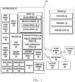
- FIG. 1 is a block diagram illustrating an electronic device 101 in a network environment 100 according to various embodiments.
- the electronic device 101 in the network environment 100 may communicate with an electronic device 102 via a first network 198 (e.g., a short-range wireless communication network), or at least one of an electronic device 104 or a server 108 via a second network 199 (e.g., a long-range wireless communication network).
- a first network 198 e.g., a short-range wireless communication network
- a second network 199 e.g., a long-range wireless communication network
- the electronic device 101 may communicate with the electronic device 104 via the server 108.
- the electronic device 101 may include a processor 120, memory 130, an input module 150, a sound output module 155, a display module 160, an audio module 170, a sensor module 176, an interface 177, a connecting terminal 178, a haptic module 179, a camera module 180, a power management module 188, a battery 189, a communication module 190, a subscriber identification module(SIM) 196, or an antenna module 197.
- at least one of the components e.g., the connecting terminal 178) may be omitted from the electronic device 101, or one or more other components may be added in the electronic device 101.
- some of the components e.g., the sensor module 176, the camera module 180, or the antenna module 197) may be implemented as a single component (e.g., the display module 160).
- the processor 120 may execute, for example, software (e.g., a program 140) to control at least one other component (e.g., a hardware or software component) of the electronic device 101 coupled with the processor 120, and may perform various data processing or computation.
- the processor 120 may store a command or data received from another component (e.g., the sensor module 176 or the communication module 190) in volatile memory 132, process the command or the data stored in the volatile memory 132, and store resulting data in non-volatile memory 134.
- the processor 120 may include a main processor 121 (e.g., a central processing unit (CPU) or an application processor (AP)), or an auxiliary processor 123 (e.g., a graphics processing unit (GPU), a neural processing unit (NPU), an image signal processor (ISP), a sensor hub processor, or a communication processor (CP)) that is operable independently from, or in conjunction with, the main processor 121.
- a main processor 121 e.g., a central processing unit (CPU) or an application processor (AP)
- auxiliary processor 123 e.g., a graphics processing unit (GPU), a neural processing unit (NPU), an image signal processor (ISP), a sensor hub processor, or a communication processor (CP)
- the main processor 121 may be adapted to consume less power than the main processor 121, or to be specific to a specified function.
- the auxiliary processor 123 may be implemented as separate from, or as part of the main processor 121.
- the auxiliary processor 123 may control at least some of functions or states related to at least one component (e.g., the display module 160, the sensor module 176, or the communication module 190) among the components of the electronic device 101, instead of the main processor 121 while the main processor 121 is in an inactive (e.g., sleep) state, or together with the main processor 121 while the main processor 121 is in an active state (e.g., executing an application).
- the auxiliary processor 123 e.g., an image signal processor or a communication processor
- the auxiliary processor 123 may include a hardware structure specified for artificial intelligence model processing.
- An artificial intelligence model may be generated by machine learning. Such learning may be performed, e.g., by the electronic device 101 where the artificial intelligence is performed or via a separate server (e.g., the server 108). Learning algorithms may include, but are not limited to, e.g., supervised learning, unsupervised learning, semi-supervised learning, or reinforcement learning.
- the artificial intelligence model may include a plurality of artificial neural network layers.
- the artificial neural network may be a deep neural network (DNN), a convolutional neural network (CNN), a recurrent neural network (RNN), a restricted boltzmann machine (RBM), a deep belief network (DBN), a bidirectional recurrent deep neural network (BRDNN), deep Q-network or a combination of two or more thereof but is not limited thereto.
- the artificial intelligence model may, additionally or alternatively, include a software structure other than the hardware structure.
- the program 140 may be stored in the memory 130 as software, and may include, for example, an operating system (OS) 142, middleware 144, or an application 146.
- OS operating system
- middleware middleware
- application application
- the input module 150 may receive a command or data to be used by another component (e.g., the processor 120) of the electronic device 101, from the outside (e.g., a user) of the electronic device 101.
- the input module 150 may include, for example, a microphone, a mouse, a keyboard, a key (e.g., a button), or a digital pen (e.g., a stylus pen).
- the display module 160 may visually provide information to the outside (e.g., a user) of the electronic device 101.
- the display module 160 may include, for example, a display, a hologram device, or a projector and control circuitry to control a corresponding one of the display, hologram device, and projector.
- the display module 160 may include a touch sensor adapted to detect a touch, or a pressure sensor adapted to measure the intensity of force incurred by the touch.
- the audio module 170 may convert a sound into an electrical signal and vice versa. According to an embodiment, the audio module 170 may obtain the sound via the input module 150, or output the sound via the sound output module 155 or a headphone of an external electronic device (e.g., an electronic device 102) directly (e.g., wiredly) or wirelessly coupled with the electronic device 101.
- an external electronic device e.g., an electronic device 102
- directly e.g., wiredly
- wirelessly e.g., wirelessly
- the sensor module 176 may detect an operational state (e.g., power or temperature) of the electronic device 101 or an environmental state (e.g., a state of a user) external to the electronic device 101, and then generate an electrical signal or data value corresponding to the detected state.
- the sensor module 176 may include, for example, a gesture sensor, a gyro sensor, an atmospheric pressure sensor, a magnetic sensor, an acceleration sensor, a grip sensor, a proximity sensor, a color sensor, an infrared (IR) sensor, a biometric sensor, a temperature sensor, a humidity sensor, or an illuminance sensor.
- the interface 177 may support one or more specified protocols to be used for the electronic device 101 to be coupled with the external electronic device (e.g., the electronic device 102) directly (e.g., wiredly) or wirelessly.
- the interface 177 may include, for example, a high definition multimedia interface (HDMI), a universal serial bus (USB) interface, a secure digital (SD) card interface, or an audio interface.
- HDMI high definition multimedia interface
- USB universal serial bus
- SD secure digital
- a connecting terminal 178 may include a connector via which the electronic device 101 may be physically connected with the external electronic device (e.g., the electronic device 102).
- the connecting terminal 178 may include, for example, an HDMI connector, a USB connector, a SD card connector, or an audio connector (e.g., a headphone connector).
- the haptic module 179 may convert an electrical signal into a mechanical stimulus (e.g., a vibration or a movement) or electrical stimulus which may be recognized by a user via his tactile sensation or kinesthetic sensation.
- the haptic module 179 may include, for example, a motor, a piezoelectric element, or an electric stimulator.
- the camera module 180 may capture a still image or moving images.
- the camera module 180 may include one or more lenses, image sensors, image signal processors, or flashes.
- the power management module 188 may manage power supplied to the electronic device 101.
- the power management module 188 may be implemented as at least part of, for example, a power management integrated circuit (PMIC).
- PMIC power management integrated circuit
- the battery 189 may supply power to at least one component of the electronic device 101.
- the battery 189 may include, for example, a primary cell which is not rechargeable, a secondary cell which is rechargeable, or a fuel cell.
- the communication module 190 may support establishing a direct (e.g., wired) communication channel or a wireless communication channel between the electronic device 101 and the external electronic device (e.g., the electronic device 102, the electronic device 104, or the server 108) and performing communication via the established communication channel.
- the communication module 190 may include one or more communication processors that are operable independently from the processor 120 (e.g., the application processor (AP)) and supports a direct (e.g., wired) communication or a wireless communication.
- AP application processor
- the communication module 190 may include a wireless communication module 192 (e.g., a cellular communication module, a short-range wireless communication module, or a global navigation satellite system (GNSS) communication module) or a wired communication module 194 (e.g., a local area network (LAN) communication module or a power line communication (PLC) module).
- a wireless communication module 192 e.g., a cellular communication module, a short-range wireless communication module, or a global navigation satellite system (GNSS) communication module
- GNSS global navigation satellite system
- wired communication module 194 e.g., a local area network (LAN) communication module or a power line communication (PLC) module.
- LAN local area network
- PLC power line communication
- a corresponding one of these communication modules may communicate with the external electronic device via the first network 198 (e.g., a short-range communication network, such as Bluetooth TM , wireless-fidelity (Wi-Fi) direct, or infrared data association (IrDA)) or the second network 199 (e.g., a long-range communication network, such as a legacy cellular network, a 5G network, a next-generation communication network, the Internet, or a computer network (e.g., LAN or wide area network (WAN)).
- first network 198 e.g., a short-range communication network, such as Bluetooth TM , wireless-fidelity (Wi-Fi) direct, or infrared data association (IrDA)
- the second network 199 e.g., a long-range communication network, such as a legacy cellular network, a 5G network, a next-generation communication network, the Internet, or a computer network (e.g., LAN or wide area network (WAN)).
- the wireless communication module 192 may identify and authenticate the electronic device 101 in a communication network, such as the first network 198 or the second network 199, using subscriber information (e.g., international mobile subscriber identity (IMSI)) stored in the subscriber identification module 196.
- subscriber information e.g., international mobile subscriber identity (IMSI)
- the wireless communication module 192 may support a 5G network, after a 4G network, and next-generation communication technology, e.g., new radio (NR) access technology.
- the NR access technology may support enhanced mobile broadband (eMBB), massive machine type communications (mMTC), or ultra-reliable and low-latency communications (URLLC).
- eMBB enhanced mobile broadband
- mMTC massive machine type communications
- URLLC ultra-reliable and low-latency communications
- the wireless communication module 192 may support a high-frequency band (e.g., the mmWave band) to achieve, e.g., a high data transmission rate.
- the wireless communication module 192 may support various technologies for securing performance on a high-frequency band, such as, e.g., beamforming, massive multiple-input and multiple-output (massive MIMO), full dimensional MIMO (FD-MIMO), array antenna, analog beam-forming, or large scale antenna.
- the wireless communication module 192 may support various requirements specified in the electronic device 101, an external electronic device (e.g., the electronic device 104), or a network system (e.g., the second network 199).
- the antenna module 197 may transmit or receive a signal or power to or from the outside (e.g., the external electronic device) of the electronic device 101.
- the antenna module 197 may include an antenna including a radiating element composed of a conductive material or a conductive pattern formed in or on a substrate (e.g., a printed circuit board (PCB)).
- the antenna module 197 may include a plurality of antennas (e.g., array antennas). In such a case, at least one antenna appropriate for a communication scheme used in the communication network, such as the first network 198 or the second network 199, may be selected, for example, by the communication module 190 (e.g., the wireless communication module 192) from the plurality of antennas.
- the signal or the power may then be transmitted or received between the communication module 190 and the external electronic device via the selected at least one antenna.
- another component e.g., a radio frequency integrated circuit (RFIC)
- RFIC radio frequency integrated circuit
- the antenna module 197 may form a mmWave antenna module.
- the mmWave antenna module may include a printed circuit board, an RFIC disposed on a first surface (e.g., the bottom surface) of the printed circuit board, or adjacent to the first surface and capable of supporting a designated high-frequency band (e.g., the mmWave band), and a plurality of antennas (e.g., array antennas) disposed on a second surface (e.g., the top or a side surface) of the printed circuit board, or adjacent to the second surface and capable of transmitting or receiving signals of the designated high-frequency band.
- a designated high-frequency band e.g., the mmWave band
- a plurality of antennas e.g., array antennas
- At least some of the above-described components may be coupled mutually and communicate signals (e.g., commands or data) therebetween via an inter-peripheral communication scheme (e.g., a bus, general purpose input and output (GPIO), serial peripheral interface (SPI), or mobile industry processor interface (MIPI)).
- an inter-peripheral communication scheme e.g., a bus, general purpose input and output (GPIO), serial peripheral interface (SPI), or mobile industry processor interface (MIPI)
- commands or data may be transmitted or received between the electronic device 101 and the external electronic device 104 via the server 108 coupled with the second network 199.
- Each of the electronic devices 102 or 104 may be a device of a same type as, or a different type, from the electronic device 101.
- all or some of operations to be executed at the electronic device 101 may be executed at one or more of the external electronic devices 102, 104, or 108. For example, if the electronic device 101 should perform a function or a service automatically, or in response to a request from a user or another device, the electronic device 101, instead of, or in addition to, executing the function or the service, may request the one or more external electronic devices to perform at least part of the function or the service.
- the one or more external electronic devices receiving the request may perform the at least part of the function or the service requested, or an additional function or an additional service related to the request, and transfer an outcome of the performing to the electronic device 101.
- the electronic device 101 may provide the outcome, with or without further processing of the outcome, as at least part of a reply to the request.
- a cloud computing, distributed computing, mobile edge computing (MEC), or client-server computing technology may be used, for example.
- the electronic device 101 may provide ultra low-latency services using, e.g., distributed computing or mobile edge computing.
- the external electronic device 104 may include an internet-of-things (IoT) device.
- the server 108 may be an intelligent server using machine learning and/or a neural network.
- the external electronic device 104 or the server 108 may be included in the second network 199.
- the electronic device 101 may be applied to intelligent services (e.g., smart home, smart city, smart car, or healthcare) based on 5G communication technology or IoT-related technology.
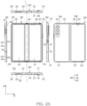
- FIG. 2A illustrates an example of an unfolding state of an electronic device according to an embodiment
- FIG. 2B illustrates an example of a folding state of an electronic device according to an embodiment
- FIG. 2C is an exploded view of an electronic device according to an embodiment.
- an electronic device 200 may include a first housing 210, a second housing 220, and a display 230 (e.g., the display module 160 of FIG. 1 ), at least one camera 240, a hinge structure 250, and/or at least one electronic component 260.
- the first housing 210 and the second housing 220 may form at least a portion of an outer surface of the electronic device 200 that may be gripped by a user. At least a portion of the outer surface of the electronic device 200 defined by the first housing 210 and the second housing 220 may be in contact with a portion of a user's body when the electronic device 200 is used by the user.
- the first housing 210 may include a first surface 211, a second surface 212 facing the first surface 211 and spaced apart from the first surface 211, and a first side surface 213 surrounding at least a portion of the first surface 211 and the second surface 212.
- the first side surface 213 may connect a periphery of the first surface 211 and a periphery of the second surface 212.
- the first surface 211, the second surface 212, and the first side surface 213 may define an inner space of the first housing 210.
- the first housing 210 may provide a space formed by the first surface 211, the second surface 212, and the first side surface 213 as the space for disposing components of the electronic device 101.
- the second housing 220 may include a third surface 221, a fourth surface 222 facing the third surface 221 and spaced apart from the third surface 221, and a second side surface 223 surrounding at least a portion of the third surface 221 and the fourth surface 222.
- the second side surface 223 may connect a periphery of the third surface 221 and a periphery of the fourth surface 222.
- the third surface 221, the fourth surface 222, and the second side surface 223 may define an inner space of the second housing 220.
- the second housing 220 may provide the space formed by the third surface 221, the fourth surface 222, and the second side surface 223 surrounding at least a portion of the third surface 221 and the fourth surface 222 as the space for mounting components of the electronic device 101.
- the second housing 220 may be coupled to the first housing 210 to be rotatable relative to the first housing 210.
- each of the first housing 210 and the second housing 220 may include each of a first protection member 214 and a second protection member 224.
- the first protection member 214 and the second protection member 224 may be disposed on the first surface 211 and the third surface 221 along a periphery of the display 230.
- the first protection member 214 and the second protection member 224 may prevent foreign substance (e.g., dust or moisture) from introducing through a gap between the display 230, the first housing 210 and the second housing 220.
- the first protection member 214 may surround a periphery of a first display region 231 of the display 230
- the second protection member 224 may surround a periphery of a second display region 232 of the display 230.
- the first protection member 214 may be formed by being attached to the first side surface 213 of the first housing 210, or may be integrally formed with the first side surface 213.
- the second protection member 224 may be formed by being attached to the second side surface 223 of the second housing 220, or may be integrally formed with the second side surface 223.
- the first side surface 213 and the second side surface 223 may include a conductive material, a non-conductive material, or a combination thereof.
- the second side surface 223 may include at least one conductive member 225 and at least one non-conductive member 226.
- the at least one conductive member 225 may include a plurality of conductive members spaced apart from each other.
- the at least one non-conductive member 226 may be disposed between the plurality of conductive members.
- the plurality of conductive members may be disconnected from each other, by the at least one non-conductive member 226 disposed between the plurality of conductive members.
- the plurality of conductive members and the plurality of non-conductive members may form an antenna radiator together.
- the electronic device 200 may be capable of communicating with an external electronic device through the antenna radiator formed by the plurality of conductive members and the plurality of non-conductive members.
- the display 230 may be configured to display visual information. According to an embodiment, the display 230 may be disposed on the first surface 211 of the first housing 210 and the third surface 221 of the second housing 220 across the hinge structure 250.
- the display 230 may include the first display region 231 disposed on the first surface 211 of the first housing, the second display region 232 disposed on the third surface 221 of the second housing, and a third display region 233 disposed between the first display region 231 and the second display region 232.
- the first display region 231, the second display region 232, and the third display region 233 may form a front surface of the display 230.
- the display 230 may further include a sub-display panel 235 disposed in the fourth surface 222 of the second housing 220.
- the display 230 may be referred to as a flexible display 230.
- the display 230 may include a window exposed toward the outside of the electronic device 200.
- the window may protect a surface of the display 230, and transfer the visual information provided by the display 230 to the outside of the electronic device 200 by including a substantially transparent material.
- the window may include glass (e.g., UTG, ultrathin glass) and/or polymer (e.g., PI, polyimide), but is not limited thereto.
- the at least one camera 240 may be configured to obtain an image based on receiving light from an external subject of the electronic device 200.
- the at least one camera 240 may include first cameras 241, a second camera 242, and a third camera 243.
- the first cameras 241 may be disposed in the first housing 210.
- the first cameras 241 may be disposed inside the first housing 210, and at least a portion of the first cameras 241 may be visible through the second surface 212 of the first housing 210.
- the first cameras 241 may be supported by a bracket (not illustrated) in the first housing 210.
- the first housing 210 may include at least one opening 241a overlapping the first cameras 241 when viewed from above the electronic device 200.
- the first cameras 241 may obtain an image based on receiving light from the outside of the electronic device 200 through the at least one opening 241a.
- the second camera 242 may be disposed in the second housing 220.
- the second camera 242 may be disposed inside the second housing 220 and may be visible through the sub-display panel 235.
- the second housing 220 may include at least one opening 242a overlapping the second camera 242 when viewed from above the electronic device 200.
- the second camera 242 may obtain an image based on receiving light from the outside of the electronic device 200 through the at least one opening 242a.
- the third camera 243 may be disposed in the first housing 210.
- the third camera 243 may be disposed inside the first housing 210, and at least a portion of the third camera 243 may be visible through the first surface 211 of the first housing 210.
- the third camera 243 may be disposed inside the first housing 210 and at least a portion of the third camera 243 may be visible through the first display region 231 of the display 230.
- the first display region 231 of the display 230 may include at least one opening overlapping the third camera 243 when viewed from above the display 230.
- the third camera 243 may obtain an image based on receiving light from the outside of the display 230 through at least one opening.
- the second camera 242 and the third camera 243 may be disposed under (e.g., in a direction toward the inside of the first housing 210 or the inside of the second housing 220) the display 230.
- the second camera 242 and the third camera 243 may be a under display camera (UDC).
- UDC under display camera
- a region of the display 230 corresponding to a location of each of the second camera 242 and the third camera 243 may not be an inactive region.
- the inactive region of the display 230 may mean a region of the display 230 that does not include a pixel or does not emit light to the outside of the electronic device 200.
- the second camera 242 and the third camera 243 may be a punch hole camera.
- the region of the display 230 corresponding to the location of each of the second camera 242 and the third camera 243 may be the inactive region.
- the hinge structure 250 may rotatably connect the first housing 210 and the second housing 220.
- the hinge structure 250 may be disposed between the first housing 210 and the second housing 220 of the electronic device 101 so that the electronic device 200 may be bent, curved, or folded.
- the hinge structure 250 may be disposed between a portion of the first side surface 213 and a portion of the second side surface 223 facing each other.
- the hinge structure 250 may change the electronic device 200 into an unfolding state in which a direction that the first surface 211 of the first housing 210 and the third surface 221 of the second housing 220 are facing is substantially the same as each other or into a folding state in which the first surface 211 and the third surface 221 face each other.
- the first housing 210 and the second housing 220 may be superimposed or overlapped by facing each other.
- a direction in which the first surface 211 faces and a direction in which the third surface 221 faces may be different from each other.
- the direction in which the first surface 211 faces and the direction in which the third surface 221 faces may be opposite to each other.
- the direction in which the first surface 211 faces and the direction in which the third surface 221 faces may be inclined relative to each other.
- the first housing 210 may be inclined relative to the second housing 220.
- the electronic device 200 may be foldable based on a folding axis f.
- the folding axis f may mean a virtual line extended through a hinge cover 251 in a direction (e.g., d1 of FIGS. 2A and 2B ) parallel to a longitudinal direction of the electronic device 200, but is not limited thereto.
- the folding axis f may be a virtual line extending in a direction (e.g., d2 in FIGS. 2A and 2B ) perpendicular to the longitudinal direction of the electronic device 200.
- the hinge structure 250 may connect the first housing 210 and the second housing 220, by extending in the direction parallel to the folding axis f.
- the first housing 210 and the second housing 220 may be rotatable by the hinge structure 250 extending in the direction perpendicular to the longitudinal direction of the electronic device 200.
- the hinge structure 250 may include the hinge cover 251, a first hinge plate 252, a second hinge plate 253, and a hinge module 254.
- the hinge cover 251 may surround internal components of the hinge structure 250 and form an outer surface of the hinge structure 250.
- at least a portion of the hinge cover 251 surrounding the hinge structure 250 may be exposed to the outside of the electronic device 200 through a space between the first housing 210 and the second housing 220.
- the hinge cover 251 when the electronic device 200 is in the unfolding state, the hinge cover 251 may not be exposed to the outside of the electronic device 200, by being covered by the first housing 210 and the second housing 220.
- the first hinge plate 252 and the second hinge plate 253 may rotatably connect the first housing 210 and the second housing 220 by being coupled to the first housing 210 and the second housing 220, respectively.
- the first hinge plate 252 may be coupled to a first front bracket 215 of the first housing 210 and the second hinge plate 253 may be coupled to a second front bracket 227 of the second housing 220.
- the first hinge plate 252 and the second hinge plate 253 are coupled to the first front bracket 215 and the second front bracket 227, respectively, the first housing 210 and the second housing 220 may be rotatable according to rotation of the first hinge plate 252 and the second hinge plate 253.
- the hinge module 254 may rotate the first hinge plate 252 and the second hinge plate 253.
- the hinge module 254 may rotate the first hinge plate 252 and the second hinge plate 253 based on the folding axis f, by including gears that may be engaged and rotated.
- there may be the plurality of hinge modules 254.
- the plurality of hinge modules 254 may be disposed, respectively by being spaced apart from each other at both ending portion of the first hinge plate 252 and the second hinge plate 253.
- the battery 264 which is a device for supplying power to at least one component of the electronic device 200, for example, may include a non-rechargeable primary battery, or a rechargeable secondary battery, or a fuel cell. At least a portion of the battery 264 may be disposed substantially on the same plane as the first printed circuit board 261 or the second printed circuit board 262.
- the electronic device 300 may be referred to as a foldable device in that a display (e.g., the display 230 of FIGS. 2A , 2B , and 2C ) is foldable.
- a display e.g., the display 230 of FIGS. 2A , 2B , and 2C
- the first housing 310 may define a portion of an outer surface of the electronic device 300.
- the second housing 320 may define another portion of the outer surface of the electronic device 300.
- the second housing 320 may be movable relative to the first housing 310.
- the second housing 320 may be coupled to the first housing 310 to be rotatable relative to the first housing 310.
- the second housing 320 may be coupled to the first housing 310 to be pivotable relative to the first housing 310.
- the second housing 320 may be coupled to the first housing 310 through a hinge structure (e.g., the hinge structure 250 of FIGS. 2A , 2B and 2C ).
- a state of the electronic device 300 may be changed.
- the display 230 may be folded or unfolded, by moving of the second housing 320 relative to the first housing 310.
- the state of the electronic device 300 may be changed to a folding state or an unfolding state.
- the display 230 may be disposed on a first surface 311 (e.g., the first surface 211 of FIGS. 2A , 2B , and 2C ) of the first housing 310, and a third surface 321 (e.g., the third surface 221 of FIGS. 2A , 2B , and 2C ) of the second housing 320.
- the first surface 311 of the first housing 310 and the third surface 321 of the second housing 320 may face each other.
- a direction in which the first surface 311 faces may face a direction opposite to a direction in which the third surface 321 faces.
- the display 230 disposed on the first surface 311 and the third surface 321 may be folded.
- the direction in which the first surface 311 faces and the direction in which the third surface 321 faces may be the same each other.
- the display 230 disposed on the first surface 311 and the third surface 321 may be unfolded.
- the first printed circuit board 331 may form an electrical connection of electronic components disposed in the first housing 310.
- the first printed circuit board 331 may be electrically connected to the electronic components in the first housing 310 and electronic components disposed in the second housing 320.
- the first printed circuit board 331 may be disposed in the first housing 310.
- the first printed circuit board 331 may include a processor (e.g., the processor 120 of FIG. 1 ) disposed on a surface of the first printed circuit board 331.
- the first printed circuit board 331 may be referred to as a main printed circuit board (PCB).
- PCB main printed circuit board
- the third printed circuit board 332 may include electronic components for implementing an interface (e.g., the interface 177 of FIG. 1 ) and a communication module (e.g., the communication module 190 of FIG. 1 ). According to an embodiment, the third printed circuit board 332 may be spaced apart from the first printed circuit board 331. The third printed circuit board 332 may be disposed in the first housing 310.
- the battery 340 may be configured to supply power to the electronic components in the electronic device 300.
- the battery 340 may include a first battery 341 and a second battery 342.
- the first battery 341 may be configured to supply power to the electronic components disposed in the first housing 310.
- the first battery 341 may be disposed in the first housing 310.
- the first battery 341 may be disposed between the first printed circuit board 331 and the third printed circuit board 333.
- the first battery 341 may include a first periphery 341a, a second periphery 341b, a third periphery 341c, and/or a fourth periphery 341d.
- a periphery, among regions included in a component, may mean a region including a boundary for distinguishing the component from other components.
- the first periphery 341a may face a side surface of the first printed circuit board 331.
- the second periphery 341b may be connected to an ending portion of the first periphery 341a.
- the second periphery 341b may extend in a direction substantially perpendicular to the first periphery 341a.
- the third periphery 341c may be connected to another ending portion of the first periphery 341a.
- Another ending portion of the first periphery 341a may be opposite to the ending portion of the first periphery 341a connected to the second periphery 341b.
- the third periphery 341c may extend in a direction substantially perpendicular to the first periphery 341a.
- the third periphery 341c may extend in a direction substantially parallel to the second periphery 341b.
- the fourth periphery 341d may connect the second periphery 341b and the third periphery 341c.
- the fourth periphery 341d may extend between the second periphery 341b and the third periphery 341c.
- the fourth periphery 341d may be substantially parallel to the first periphery 341a. According to an embodiment, the fourth periphery 341d may face a side surface of the third printed circuit board 333.
- the first printed circuit board 331 may be spaced apart from a battery 341 along a first direction (e.g., a +y direction).
- the first printed circuit board 331 may be spaced apart from the first periphery 341a in the first direction (e.g., the +y direction).
- the second printed circuit board 332 may be spaced apart from the battery 341 along a second direction different from the first direction.
- the second direction may indicate a direction distinguished from the first direction.
- the second direction may indicate at least one of a direction opposite to the first direction, a direction inclined relative to the first direction, or a direction perpendicular to the first direction.
- the second printed circuit board 332 may be spaced apart from the first periphery 341a along the second direction (e.g., a +x direction) different from the first direction.
- the third printed circuit board 333 may be spaced apart from the battery 341 along the second direction different from the first direction.
- the third printed circuit board 333 may be spaced apart from the first periphery 341a along the second direction (e.g., a -y direction) different from the first direction.
- the second battery 342 may be configured to supply power to the electronic components disposed in the second housing 320.
- the second battery 342 may be disposed in the second housing 320.
- the second battery 342 may be spaced apart from the first battery 341.
- the first tape 351 may be disposed on the second periphery 341b.
- the first tape 351 may extend along the second periphery 341b.
- the first tape 351 may extend from an ending portion of the second periphery 341b in contact with the first periphery 341a to another ending portion of the second periphery 341b in contact with the fourth periphery 341d.
- the first tape 351 may surround a portion of a surface 341e of the first battery 341, a portion of a side surface of the first battery 341 facing an -x axis direction, and a portion of another surface of the first battery 341 opposite to the surface 341e of the first battery 341.
- a direction (e.g., a -z direction) in which another surface of the first battery 341 faces may be opposite to a direction (e.g., a +z direction) in which the surface 341e of the first battery 341 faces.
- the side surface of the first battery may mean a surface connecting the surface 341e of the first battery 341 and another surface of the first battery 341.
- the third tape 353 may overlap at least a portion of the first tape 351.
- the third tape 353 may be disposed on the first tape 351.
- the third tape 353 may surround the ending portion of the second periphery 341b in contact with the first periphery 341a.
- the third tape 353 may surround the portion of the surface 341e of the first battery 341, the portion of the side surface of the first battery 341 facing a +y axis direction, and the portion of another surface of the first battery 341 opposite to the surface 341e of the first battery 341.
- the fourth tape 354 may be spaced apart from the second tape 352 when viewed from above the first battery 341.
- the fourth tape 354 may be disposed between the first tape 351 and the second tape 352 when viewed from above the first battery 341.
- the fourth tape 354 may be spaced apart from the third periphery 341c.
- the fourth tape 354 may be connected to the second tape 352 on the side surface of the first battery 341 facing the first printed circuit board 331.
- the fourth tape 354 may overlap the portion of the second tape 352 disposed on the side surface of the first battery 341 facing the first printed circuit board 331.
- the fourth tape 354 may surround the portion of the surface 341e of the first battery 341, the portion of the side surface of the first battery 341 facing a +y axis direction, and the portion of another surface of the first battery 341 opposite to the surface 341e of the first battery 341.
- the plurality of flexible printed circuit boards 360 may connect the plurality of printed circuit boards 330 to each other.
- the plurality of flexible printed circuit boards 360 may electrically connect the plurality of printed circuit boards 330.
- the plurality of flexible printed circuit boards 360 may electrically connect one of the plurality of printed circuit boards 330 and the other of the plurality of printed circuit boards 330 through a connector, but it is not limited thereto.
- the plurality of flexible printed circuit boards 360 may be manufactured integrally with at least a portion of the plurality of printed circuit boards 330.
- the plurality of flexible printed circuit boards 360 may have a curved shape in the electronic device 300.
- the plurality of flexible printed circuit boards 360 may have flexibility and bent in the electronic device 300.
- the plurality of flexible printed circuit boards 360 may include a first flexible printed circuit board 361, a second flexible printed circuit board 362, a third flexible printed circuit board 363, and/or a fourth flexible printed circuit board 364.
- the first flexible printed circuit board 361 may electrically connect the first printed circuit board 331 and the second printed circuit board 332.
- the first flexible printed circuit board 361 may perform transmission of a signal for an overall operation of the electronic device 300.
- an audio signal may be transmitted to the first printed circuit board 331 or the second printed circuit board 332 through the first flexible printed circuit board 361.
- a signal obtained by an input from an external object e.g., an electronic pen
- the first flexible printed circuit board 361 may extend from the first printed circuit board 331 in the first housing 310 to the second printed circuit board 332 in the second housing 320.
- an ending portion of the first flexible printed circuit board 361 may be disposed on the first printed circuit board 331, and another ending portion of the first flexible printed circuit board 361 opposite to the ending portion of the first flexible printed circuit board 361 may be disposed on the second printed circuit board 332.
- the first flexible printed circuit board 361 may be disposed on the surface 341e of the first battery 341.
- the first flexible printed circuit board 361 may cross the first battery 341.
- the first flexible printed circuit board 361 may be disposed on the surface 341e of the first battery 341.
- the portion of the first flexible printed circuit board 361 may be disposed on the first periphery 341a of the first battery 341 facing the first printed circuit board 331.
- the first flexible printed circuit board 361 may be bent on the surface 341e of the first battery 341.
- the first flexible printed circuit board 361 may be bent on the surface 341e of the first battery 341 and disposed on the third periphery 342b of the first battery 341.
- the first flexible printed circuit board 331 when viewed from above the first battery 341, may overlap a portion of the first battery 341.
- the first flexible printed circuit board 331 may overlap the first periphery 341a and the third periphery 341c.
- the first flexible printed circuit board 331 when viewed from above the first battery 341, may not overlap the second periphery 341b and the fourth periphery 341d.
- the first flexible printed circuit board 331 may be spaced apart from the second periphery 341b and the fourth periphery 341d.
- the second flexible printed circuit board 362 may electrically connect the first printed circuit board 331 and the third printed circuit board 333.
- the second flexible printed circuit board 362 may perform transmission of a signal between an interface (e.g., the interface 177 of FIG. 1 ) of the electronic device 300 and the first printed circuit board 331.
- the second flexible printed circuit board 362 may transmit the signal inputted from an external electronic device (e.g., the electronic device 102 of FIG. 1 ) to the first printed circuit board 362.
- the second flexible printed circuit board 362 may extend from the first printed circuit board 331 to the third printed circuit board 333.
- an ending portion of the second flexible printed circuit board 362 may be disposed on the first printed circuit board 331, and another ending portion of the second flexible printed circuit board 362 opposite to the ending portion of the second flexible printed circuit board 362 may be disposed on the third printed circuit board 333.
- the second flexible printed circuit board 362 may cross the first battery 341.
- the second flexible printed circuit board 362 may extend from the first printed circuit board 331 to the third printed circuit board 333 along the direction (e.g., the -y direction) perpendicular to the first periphery 341a.
- the second flexible printed circuit board 362 may extend along a direction (e.g., the -y direction) from the first periphery 341a toward the fourth periphery 341b.
- the second flexible printed circuit board 362 may overlap the first periphery 341a and the fourth periphery 341d.
- the second flexible printed circuit board 362 may not overlap the second periphery 341b and the third periphery 341d.
- the second flexible printed circuit board 362 may be disposed between the second periphery 341b and the third periphery 341d.
- the third flexible printed circuit board 363 may electrically connect the first printed circuit board 331 and the third printed circuit board 333.
- the third flexible printed circuit board 363 may perform transmission of an RF signal between the first printed circuit board 331 and the third printed circuit board 333.
- the third flexible printed circuit board 363 may overlap the third periphery 341c and the fourth periphery 341d.
- the third flexible printed circuit board 363 may not overlap the first periphery 341a and the second periphery 341b.
- the fourth flexible printed circuit board 364 may electrically connect the first printed circuit board 331 and the second printed circuit board 332.
- the fourth flexible printed circuit board 364 may perform transmission of a signal for an overall operation of the electronic device 300.
- the fourth flexible printed circuit board 364 may transmit a signal between the first printed circuit board 331 and the second printed circuit board 362 together with the first flexible printed circuit board 361.
- the fourth flexible printed circuit board 364 may extend from the first printed circuit board 331 to the second printed circuit board 332.
- the fourth flexible printed circuit board 364 may be spaced apart from the first flexible printed circuit board 361.
- the fourth flexible printed circuit board 364 may extend from the first housing 310, across the hinge structure (e.g., FIGS. 2A , 2B , and 2C ), to the second housing 320.
- a portion 341a-1 of the first periphery 341a may be exposed in a direction (e.g., a +z direction) toward the first flexible printed circuit board 361 between the first tape 351 and the second tape 352.
- the plurality of tapes 350 may not be disposed on the portion 341a-1 of the first periphery 341a.
- the portion 341a-1 of the first periphery 341a may be spaced apart from the plurality of tapes 350.
- the portion 341a-1 of the first periphery 341a may be exposed toward the first flexible printed circuit board 361 between the third tape 353 and the fourth tape 354.
- the fourth tape 354 may surround another portion 341a-2 of the first periphery 341a between the first flexible printed circuit board 361 and the second tape 352.
- the portion 341a-1 of the first periphery 341a may be disposed between the first tape 351 and the second tape 352, and may face the first flexible printed circuit board 361 through a gap g1 between the first tape 351 and the second tape 352.
- the portion 341a-1 of the first periphery 341a may mean a region of the first battery 341 in which a protection circuit module (PCM) of the first battery 341 is not included among the regions of the first battery 341.
- the gap g1 may mean a region of the first battery 341 in which the plurality of tapes 350 is not disposed.
- the gap g1 may be formed by being spaced apart from the first tape 351 along a direction (e.g., a +x direction) in which the second tape 352 faces the third periphery 341c from the second periphery 341b.
- the portion 341a-1 of the first periphery 341a may be spaced apart from the first flexible printed circuit board 361 in the gap g1 between the first tape 351 and the second tape 352.
- the portion 341a-1 of the first periphery 341a may be in contact with the first flexible printed circuit board 361 in the gap g1 between the first tape 351 and the second tape 352.
- the portion 341a-1 of the first periphery 341a may form a step with other regions of the first battery 341.
- a size of a space in the first housing 310 accommodating the first battery 341 may be designed based on a sum of a thickness of the first battery 341 and the thickness of the plurality of tapes 350.
- a thickness of a component may mean a distance in a direction (e.g., a -z direction) opposite to a direction (a +z direction) in which a surface 341e of the first battery 341 faces, and the corresponding expression may be used in the same way in the following.
- the plurality of tapes 350 is disposed in the portion 341a-1 of the first periphery 341a, the size of the space accommodating the first battery 341 may be reduced by the thickness of the plurality of tapes 350.
- a portion of a plurality of layers in the first flexible printed circuit board 361 may be omitted.
- transmission efficiency of the signal between the first printed circuit board 331 and the second printed circuit board 332 may be reduced.
- data transmission efficiency between the first printed circuit board 331 and the second printed circuit board 332 may be reduced.
- the electronic device 300 may provide a structure capable of increasing the size of the space accommodating the first battery 341. As the size of the space accommodating the first battery 341 increases, the electronic device 300 may provide a structure in which a size of the first battery 341 is increased.
- the portion 341a-1 of the first periphery 341a may be exposed toward the second flexible printed circuit board 362 between the first tape 351 and the second tape 352.
- the portion 341a-1 of the first periphery 341a may be disposed between the first tape 351 and the second tape 352, and may face the second flexible printed circuit board 362 through the gap g1 between the first tape 351 and the second tape 352.
- the portion 341a-1 of the first periphery 341a may be spaced apart from the second flexible printed circuit board 362 in the gap g1 between the first tape 351 and the second tape 352.
- the portion 341a-1 of the first periphery 341a may be in contact with the second flexible printed circuit board 362 in the gap g1 between the first tape 351 and the second tape 352.
- a portion 341d-1 of the fourth periphery 341d may be exposed in a direction (e.g., a +z direction) toward the second flexible printed circuit board 362 between the first tape 351 and the second tape 352.
- the portion 341d-1 of the fourth periphery 341d may be disposed between the first tape 351 and the second tape 352, and may face the second flexible printed circuit board 362 through the gap g1 between the first tape 351 and the second tape 352.
- the portion 341d-1 of the fourth periphery 341d may be spaced apart from the second flexible printed circuit board 362 in the gap between the first tape 351 and the second tape 352.
- the portion 341d-1 of the fourth periphery 341d may be in contact with the second flexible printed circuit board 362 in the gap between the first tape 351 and the second tape 352.
- the electronic device 300 since the portion 341a-1 of the first periphery 341a faces the first flexible printed circuit board 361 through the gap between the first tape 351 and the second tape 352, the electronic device 300 according to an embodiment may provide the structure in which the size of the first battery 341 is increased. Since the portion 341a-1 of the first periphery 341a faces the second flexible printed circuit board 362 through the gap between the first tape 351 and the second tape 352, the electronic device 300 according to an embodiment may provide the structure in which the size of the first battery 341 is increased.
- FIG. 4A is a cross-sectional view illustrating an example of an exemplary electronic device cut along line B-B' of FIG. 3A , according to an embodiment
- FIG. 4B is a perspective view illustrating a portion of a battery of an exemplary electronic device according to an embodiment
- FIG. 4C is a cross-sectional view illustrating an example of a battery of an exemplary electronic device cut along line C-C' of FIG. 4B , according to an embodiment.
- a first tape 351 may surround a second periphery 341b of a first battery 341.
- the first tape 351 may surround an outer surface of the second periphery 341b and have a shape corresponding to the outer surface of the second periphery 341b.
- the first tape 351 may have curvature and be bent on the second periphery 341b.
- a third tape 353 may surround the first tape 351.
- the third tape 353 may surround the first tape 351 on the first tape 351.
- the third tape 353 may have curvature and be bent on the second periphery 341b.
- the third tape 353 may overlap the first tape 351.
- the third tape 353 and the first tape 351 may seal a first battery 341.
- a second tape 352 may surround a third periphery 341c of the first battery 341.
- the second tape 352 may surround an outer surface of the third periphery 341c and have a shape corresponding to the outer surface of the third periphery 341c.
- the second tape 352 may have curvature and be bent on the third periphery 341c.
- the second tape 352 may surround a side surface 341f of the first battery 341.
- the side surface 341f of the first battery 341 may face a side surface of a first printed circuit board (e.g., the first printed circuit board 331 of FIG. 3A ).
- a fourth tape 354 may surround a portion of the second tape 352.
- the fourth tape 354 may surround the portion of the second tape 352 on the second tape 352.
- a portion of the fourth tape 354 may surround the portion of the second tape 352 disposed on the side surface 341f of the first battery 341.
- the portion of the fourth tape 354 may overlap the portion of the second tape 352 on the side surface 341f of the first battery 341.
- the fourth tape 354 and the second tape 352 may seal the first battery 341.
- another portion of the fourth tape 354 may be disposed on a surface 341e of the first battery 341.
- the fourth tape 354 may surround the second tape 352 on the side surface 341f of the first battery 341 and extend to the surface 341e of the first battery 341.
- the second tape 352 and the fourth tape 354 may be spaced apart from each other, on the surface 341e of the first battery 341.
- the electronic device (e.g., the electronic device 300 of FIG. 3A ) according to an embodiment may provide a structure capable of sealing the first battery 341 by a plurality of tapes 350 overlapping each other.
- a first flexible printed circuit board 361 may include a first extending portion 361a, a second extending portion 361b, and/or a third extending portion 361c.
- the first extending portion 361a may extend along a direction (e.g., a -y direction) perpendicular to a first periphery 341a.
- the first extending portion 361a may extend on a surface 341e of a first battery 341 along the direction perpendicular to the first periphery 341a.
- an ending portion of the first extending portion 361a may be disposed on a first printed circuit board 331.
- the first extending portion 361a may extend from the first printed circuit board 331 to a direction (e.g., the -y direction) from the first periphery 341a toward a fourth periphery 341d. A portion of the first extending portion 361a may overlap the first periphery 341a when viewed from above the first battery 341.
- the second extending portion 361b may be connected to the first extending portion 361a.
- the second extending portion 361b may extend from the first extending portion 361a toward a third periphery 341c.
- the second extending portion 361b may extend in a direction (e.g., a +x direction) toward the third periphery 341c on the surface 341e of the first battery 341.
- a portion of the second extending portion 361b may overlap the third periphery 341c when viewed from above the first battery 341.
- the portion of the second extending portion 361b may be disposed on the third periphery 341c.
- the third extending portion 361c may be connected to the first extending portion 361a.
- the third extending portion 361c may be spaced apart from the second extending portion 361b.
- the third extending portion 361c may extend from the first extending portion 361a toward the third periphery 341c.
- the third extending portion 361c may extend in the direction (e.g., the +x direction) toward the third periphery 341c on the surface 341e of the first battery 341.
- a portion of the third extending portion 361c may overlap the third periphery 341c.
- the portion of the third extending portion 361c may be disposed on the third periphery 341c.
- the first housing 310 may include a through hole 310a penetrating the first housing 310.
- the through hole 310a may be disposed close to the third periphery 341c among the second periphery 341b and the third periphery 341c.
- the third extending portion 361c may extend to a second housing (e.g., the second housing 320 of FIG. 3A ) via the through hole 310a.
- the third extending portion 361c may extend parallel to the surface 341e of the first battery 341.
- the third extending portion 361c may be bent at a location adjacent to the through hole 310a after passing through the third periphery 341c.
- a bent third extending portion 361c may be inserted into the through hole 310a.
- the third extending portion 361c may extend, passing through the through hole 310a, to a second printed circuit board (e.g., the second printed circuit board 332 of FIG. 3A ) in the second housing 320.
- a second printed circuit board e.g., the second printed circuit board 332 of FIG. 3A
- the electronic device 300 may provide a structure in which the first flexible printed circuit board 361 may be stably supported through the second extending 361b coupled to the first housing 310.
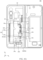
- FIG. 6A is a top plan view of an exemplary electronic device according to an embodiment
- FIG. 6B is a cross-sectional view illustrating an example of an antenna module of an exemplary electronic device cut along E-E' of FIG. 6A , according to an embodiment.
- an electronic device 300 may include an antenna module 370.
- the antenna module 370 may receive a signal from an external electronic device or transmit the signal to the external electronic device.
- the antenna module 370 may receive power from an outside of the electronic device 300 and transfer the received power to the first printed circuit board 331.
- the antenna module 370 may transfer the received AC power to the first printed circuit board 331.
- the first printed circuit board 331 may include a wireless charging circuit configured to convert the AC power transferred from the antenna module 370. Based on receiving the AC power from the antenna module 370, the wireless charging circuit of the first printed circuit board 331 may convert the received AC power into DC power.
- the wireless charging circuit of the first printed circuit board 331 may store the converted DC power in a battery 340.
- the antenna module 370 may include at least one of a near field communication (NFC) antenna and a magnetic secure transmission (MST) antenna, but is not limited thereto.
- NFC near field communication
- MST magnetic secure transmission
- the antenna module 370 may be disposed on a surface 341e of a first battery 341.
- the antenna module 370 may be spaced apart from the surface 341e of the first battery 341 along a direction (e.g., a +z direction) in which the surface 341e of the first battery 341 faces.
- the antenna module 370 when viewed from above the first battery 341, may overlap the first battery 341.
- the antenna module 370 when viewed from above the first battery 341, the antenna module 370 may overlap a first periphery 341a, a second periphery 341b, and a third periphery 341c of the first battery 341.
- the antenna module 370 may be spaced apart from a fourth periphery 341d.
- the antenna module 370 may include a first region 370a and a second region 370b.
- the first region 370a may overlap a first flexible printed circuit board 361 disposed on the third periphery 341c.
- the first region 370a may overlap a second extending portion 361b and a third extending portion 361c of the first flexible printed circuit board 361.
- the first region 370a may be disposed on the third periphery 341c and the first flexible printed circuit board 361.
- the second region 370b may be connected to the first region 370a. According to an embodiment, the second region 370b may surround at least a portion of the first region 370a. For example, when viewed from above the first battery 341, the second region 370b may overlap only the first extending portion 361a of the first flexible printed circuit board 361. According to an embodiment, when viewed from above the first battery 341, the second region 370b may overlap only one of a plurality of tapes 350 and the first flexible printed circuit board 361. For example, when viewed from above the first battery 341, a portion of the second region 370b may overlap the plurality of tapes 350 and may not overlap the first flexible printed circuit board 361. For example, when viewed from above the first battery 341, another portion of the second region 370b may overlap the first flexible printed circuit board 361 and may not overlap the plurality of tapes 350.
- the antenna module 370 may include a first coverlay 371, a first conductive layer 372, a non-conductive layer 373, a second conductive layer 374, and/or a second coverlay 375.
- the first coverlay 371 may protect layers 372, 373, 374, and 375 included in the antenna module 370.
- the first coverlay 371 may include insulating material.
- the first conductive layer 372 may form a signal pattern of the antenna module 370.
- the first conductive layer 372 may transmit or receive a signal for communication with the outside of the electronic device 300.
- the first conductive layer 372 may receive power from the outside of the electronic device 300 or transmit the power to the outside of the electronic device 300.
- the first conductive layer 372 may include conductive material.
- the first conductive layer 372 may be disposed on the first coverlay 371.
- the first conductive layer 372 may be in contact with a surface of the first coverlay 371.
- the non-conductive layer 373 may be disposed on the first conductive layer 372.
- the non-conductive layer 373 may be in contact with a surface of the first conductive layer 372.
- the non-conductive layer 373 may electrically separate the first conductive layer 372 and the second conductive layer 374.
- the non-conductive layer 373 may include non-conductive material.
- the non-conductive layer 373 may be interposed between the first conductive layer 372 and the second conductive layer 374.
- the second conductive layer 374 may form the signal pattern of the antenna module 370.
- the second conductive layer 374 may transmit or receive the signal for communication with the outside of the electronic device 300.
- the second conductive layer 374 may receive the power from the outside of the electronic device 300 or transmit the power to the outside of the electronic device 300.
- the second conductive layer 374 may include a conductive material.
- the second conductive layer 374 may be disposed on the non-conductive layer 373.
- the second conductive layer 374 may be in contact with a surface of the non-conductive layer 373.
- the second conductive layer 374 may be disposed only in the second region 370b among the first region 370a and the second region 370b.
- the second conductive layer 374 may not be disposed in the first region 370a.
- the second conductive layer 374 may be electrically connected to the first conductive layer 372 through a conductive via.
- the second coverlay 375 may protect the layers 372, 373, 374, and 375 included in the antenna module 370.
- the second coverlay 375 may include a non-conductive material.
- the second coverlay 375 may be disposed on the non-conductive layer 373.
- the second coverlay 375 in the first area 370a, the second coverlay 375 may be in contact with the surface of the non-conductive layer 373.
- the second coverlay 375 may be disposed on the second conductive layer 374 disposed on the non-conductive layer 373.
- the second coverlay 375 may be in contact with a surface of the second conductive layer 374.
- the second region 370b may have a thickness thicker than the first region 370a.
- the number of conductive layers included in the first region 370a may be smaller than the number of conductive layers included in the second region 370b.
- the second region 370b may include the first conductive layer 372 and the second conductive layer 374, and the first region 370a may include only the first conductive layer 372.
- the first region 370a may overlap both the plurality of tapes 350 and the first flexible printed circuit board 361.
- the first region 370a may overlap the second tape 352 and the first flexible printed circuit board 361 on the third periphery 341c of the first battery 341.
- a space for disposing the first battery 341 in the electronic device 300 may be reduced.
- a thickness of the first battery 341 may be reduced.
- the electronic device 300 may provide a structure in which the thickness of the first battery 341 may increase.
- the electronic device 300 may provide the structure in which the thickness of the first battery 341 may increase by the first region 370a having the thickness thinner than the second region 370b.
- the antenna module 370 included the first coverlay 371, the first conductive layer 372, the non-conductive layer 373, the second conductive layer 374, and the second coverlay 375, but this is for convenience of explanation.
- the antenna module 370 may further include a shielding layer for shielding an electromagnetic wave.
- Various components of an electronic device may be disposed adjacent to each other in a limited space in the electronic device, by miniaturizing the electronic device to enhance a user portability.
- the components may overlap each other.
- a thickness of the battery disposed in the electronic device may be reduced.
- the electronic device may not provide various functions to a user.
- the electronic device may need a structure capable of increasing a size of the battery to enhance user convenience.
- an electronic device may include a first housing (e.g., the first housing 310 of FIG. 3A ).
- the electronic device may include a second housing (e.g., the second housing 320 of FIG. 3A ) rotatable relative to the first housing.
- the electronic device may include a hinge structure (e.g., the hinge structure 250 of FIGS. 2A , 2B , and 2C ) disposed between the first housing and the second housing, and coupling the first housing and the second housing.
- the electronic device may include a flexible display (e.g., the display 230 of FIGS.
- the electronic device may include a first printed circuit board (e.g., the first printed circuit board 331 of FIG. 3A ) disposed within the first housing.
- the electronic device may include a second printed circuit board (e.g., the second printed circuit board 332 of FIG. 3A ) disposed within the second housing.
- the electronic device may include a battery (e.g., the first battery 341 of FIGS. 3A and 3B ) including a first periphery (e.g., the first periphery 341a of FIG. 3A ), a second periphery (e.g., the second periphery 341b of FIG. 3A ) connected to an ending portion of the first periphery, and a third periphery (e.g., the third periphery 341c of FIG. 3A ) connected to another ending portion of the second periphery, and disposed in the first housing.
- a battery e.g., the first battery 341 of FIGS. 3A and 3B
- a battery including a first periphery (e.g., the first periphery 341a of FIG. 3A ), a second periphery (e.g., the second periphery 341b of FIG. 3A ) connected to an ending portion of the first periphery
- the electronic device may include a first flexible printed circuit board (e.g., the first flexible printed circuit board 361 of FIGS. 3A and 3B ) electrically connecting the first printed circuit board and the second printed circuit board, and wherein a portion of the first flexible printed circuit board overlaps on a portion (e.g., the portion 341a-1 of a first periphery 341a of FIGS. 3A and 3B ) of the first periphery.
- the electronic device may include a plurality of tapes (e.g., the plurality of tapes 350 of FIG. 3A ) surrounding the battery.
- the plurality of tapes may include a first tape (e.g., the first tape 351 of FIG.
- the plurality of tapes may include a second tape (e.g., the second tape 352 of FIG. 3A ) in contact with the third periphery.
- the portion of the first periphery may be disposed between the first tape and the second tape, and face the first printed circuit board through a gap (e.g., the gap g1 of FIG. 3B ) between the first tape and the second tape.
- the electronic device may provide a structure in which a size of a battery is increased.
- the plurality of tapes may include a third tape (e.g., the third tape 353 of FIG. 3A ) surrounding a corner of the first battery where the first periphery and the second periphery are in contact with each other, and in contact with the first tape.
- the plurality of tapes may include a fourth tape (e.g., the fourth tape 354 of FIG. 3A ), spaced apart from the second tape when viewed from above the battery, and in contact with another portion (e.g., another portion 341a-2 of the first periphery 341a of FIG. 3A ) of the first periphery.
- the first flexible printed circuit board may be disposed between the third tape and the fourth tape.
- the electronic device may provide a structure in which a first flexible printed circuit board and a plurality of tapes are spaced apart. As the first flexible printed circuit board and the plurality of tapes are spaced apart, the electronic device may provide the structure in which the size of the battery is increased.
- a portion of the second tape may be in contact with a side surface (e.g., the side surface 341f of FIG. 4B ) of the battery facing the first printed circuit board.
- the fourth tape may be in contact with an outer surface of the second tape.
- the electronic device may provide a structure capable of increasing the size of the battery, while sealing the battery.
- the electronic device may include an antenna module (e.g., an antenna module 370 of FIGS. 6A and 6B ) disposed on a surface of the battery.
- the antenna module may include a first region (e.g., the first region 370a of FIGS. 6A and 6B ) that is disposed on another portion of the first flexible printed circuit board overlapping the third periphery.
- the antenna module may include a second region (e.g., the second region 370b of FIGS. 6A and 6B ) connected to the first region, and having a thickness thicker than the first region.
- the electronic device may provide a structure in which a thickness of a battery may increase by the first region having a thickness thinner than the second region.
- the number of conductive layers (e.g., the first conductive layer 372 and the second conductive layer 374 of FIG. 6B ) included in the first region may be smaller than the number of conductive layers included in the second region.
- the electronic device may provide a structure in which the thickness of a battery may increase by the first region having the thickness thinner than the second region.
- the first flexible printed circuit board may include a first extending portion (e.g., the first extending portion 361a of FIG. 5A ) extending on a surface of the battery along a direction perpendicular to the first periphery.
- the first flexible printed circuit board may include a second extending portion (e.g., the second extending portion 361b of FIG. 5A ) extending perpendicularly to the first extending portion.
- the first flexible printed circuit board may include a third extending portion (e.g., the third extending portion 361c of FIG. 5A ) extending perpendicularly to the first extending portion, and spaced apart from the second extending portion.
- the electronic device may provide a structure in which the first flexible printed circuit board may be stably supported through the second extending portion fixed to the first housing.
- an ending portion of the second extending portion may be fixed to the first housing.
- the electronic device may provide the structure in which the first flexible printed circuit board may be stably supported through the second extending portion fixed to the first housing.
- the third extending portion may extend to the second housing via a through hole (e.g., the through hole 310a of FIGS. 6A and 6B ) penetrating the first housing.
- a through hole e.g., the through hole 310a of FIGS. 6A and 6B
- the first printed circuit board and the second printed circuit board may be electrically connected through the first flexible printed circuit board.
- the electronic device may include a third printed circuit board (e.g., the third printed circuit board 333 of FIG. 3A ) disposed within the first housing.
- the electronic device may include a second flexible printed circuit board (e.g., the second flexible printed circuit board 362 of FIG. 3A ) extending between the first printed circuit board and the third printed circuit board across the battery.
- the portion of the first periphery may face the second flexible printed circuit board through a gap between the first tape and the second tape.
- the electronic device may provide the structure in which the size of the battery is increased.
- the battery may include a fourth periphery (e.g., the fourth periphery 341d of FIG. 3A ) opposite to the first periphery.
- a portion of the fourth periphery may face the second flexible printed circuit board through the gap between the first tape and the second tape.
- the electronic device may provide the structure in which the size of the battery is increased.
- the second flexible printed circuit board may extend from the first printed circuit board to the third printed circuit board along a direction perpendicular to the first periphery.
- the first printed circuit board may include a processor (e.g., the processor 120 of FIG. 1 ) disposed on a surface of the first printed circuit board.
- a processor e.g., the processor 120 of FIG. 1
- the plurality of tapes may be informed by an insulating material.
- the electronic device may provide a structure capable of preventing a short circuit of the battery through the plurality of tapes surrounding the battery.
- the first periphery may face a side surface of the first printed circuit board.
- the first flexible printed circuit board may cover the first periphery and the third periphery, and may be spaced apart from the second periphery.
- an electronic device may include a housing (e.g., the first housing 310 of FIG. 3A ).
- the electronic device may include a first printed circuit board (e.g., the first printed circuit board 331 of FIG. 3A ) disposed within the housing.
- the electronic device may include a second printed circuit board (e.g., the third printed circuit board 333 of FIG. 3A ) disposed within the housing, and spaced apart from the first printed circuit board.
- the electronic device may include a battery (e.g., the first battery 341 of FIGS.
- the electronic device may include a flexible printed circuit board (e.g., the second flexible printed circuit board 362 of FIG.
- the electronic device may include a plurality of tapes (e.g., the plurality of tapes 350 of FIG. 3A ) surrounding the battery.
- the plurality of tapes may include a first tape (e.g., the first tape 351 of FIG. 3A ) extending along the second periphery.
- the plurality of tapes may include a second tape (e.g., the second tape 352 of FIG. 3A ) extending along the third periphery.
- the portion of the first periphery may be disposed between the first tape and the second tape, and face the flexible printed circuit board through a gap between the first tape and the second tape.
- the electronic device may provide a structure in which a size of a battery is increased.
- the plurality of tapes may include a third tape (e.g., the third tape 353 of FIG. 3A ), surrounding an ending portion of the second periphery in contact with the first periphery, and disposed on the first tape.
- the plurality of tapes may include a fourth tape (e.g., the fourth tape 354 of FIG. 3A ), spaced apart from the second tape when viewed from above the battery, and surrounding another portion (e.g., another portion 341a-2 of the first periphery 341a of FIG. 3A ) of the first periphery.
- the flexible printed circuit board may be disposed between the third tape and the fourth tape.
- the electronic device may provide a structure in which the first flexible printed circuit board and the plurality of tapes are spaced apart. As the first flexible printed circuit board and the plurality of tapes are spaced apart, the electronic device may provide a structure in which the size of the battery is increased.
- the flexible printed circuit board may extend, across the battery, on a surface (e.g., the surface 341e of FIG. 3A ) of the battery.
- the battery may include a fourth periphery (e.g., the fourth periphery 341d of FIG. 3A ) opposite to the first periphery.
- a portion of the fourth periphery may face the flexible printed circuit board through the gap between the first tape and the second tape.
- the electronic device may provide the structure in which the size of the battery is increased.
- the flexible printed circuit board when viewed from above the battery, may overlap the first periphery. According to an embodiment, the flexible printed circuit board may be spaced apart from the second periphery, and the third periphery.
- the electronic device may be one of various types of electronic devices.
- the electronic devices may include, for example, a portable communication device (e.g., a smartphone), a computer device, a portable multimedia device, a portable medical device, a camera, a wearable device, or a home appliance. According to an embodiment of the disclosure, the electronic devices are not limited to those described above.
- each of such phrases as “A or B,” “at least one of A and B,” “at least one of A or B,” “A, B, or C,” “at least one of A, B, and C,” and “at least one of A, B, or C,” may include any one of or all possible combinations of the items enumerated together in a corresponding one of the phrases.
- such terms as “1st” and “2nd,” or “first” and “second” may be used to simply distinguish a corresponding component from another, and does not limit the components in other aspect (e.g., importance or order).
- an element e.g., a first element
- operatively or “communicatively”, as “coupled with,” or “connected with” another element
- the element may be coupled with the other element directly (e.g., wiredly), wirelessly, or via a third element.
- module may include a unit implemented in hardware, software, or firmware, and may interchangeably be used with other terms, for example, “logic,” “logic block,” “part,” or “circuitry”.
- a module may be a single integral component, or a minimum unit or part thereof, adapted to perform one or more functions.
- the module may be implemented in a form of an application-specific integrated circuit (ASIC).
- ASIC application-specific integrated circuit
- Various embodiments as set forth herein may be implemented as software (e.g., the program 140) including one or more instructions that are stored in a storage medium (e.g., internal memory 136 or external memory 138) that is readable by a machine (e.g., the electronic device 101).
- a processor e.g., the processor 120
- the machine e.g., the electronic device 101
- the one or more instructions may include a code generated by a complier or a code executable by an interpreter.
- the machine-readable storage medium may be provided in the form of a non-transitory storage medium.
- non-transitory simply means that the storage medium is a tangible device, and does not include a signal (e.g., an electromagnetic wave), but this term does not differentiate between a case in which data is semi-permanently stored in the storage medium and a case in which the data is temporarily stored in the storage medium.
- a method may be included and provided in a computer program product.
- the computer program product may be traded as a product between a seller and a buyer.
- the computer program product may be distributed in the form of a machine-readable storage medium (e.g., compact disc read only memory (CD-ROM)), or be distributed (e.g., downloaded or uploaded) online via an application store (e.g., PlayStore TM ), or between two user devices (e.g., smart phones) directly. If distributed online, at least part of the computer program product may be temporarily generated or at least temporarily stored in the machine-readable storage medium, such as memory of the manufacturer's server, a server of the application store, or a relay server.
- CD-ROM compact disc read only memory
- an application store e.g., PlayStore TM
- two user devices e.g., smart phones
- each component e.g., a module or a program of the above-described components may include a single entity or multiple entities, and some of the multiple entities may be separately disposed in different components. According to various embodiments, one or more of the above-described components may be omitted, or one or more other components may be added. Alternatively or additionally, a plurality of components (e.g., modules or programs) may be integrated into a single component. In such a case, according to various embodiments, the integrated component may still perform one or more functions of each of the plurality of components in the same or similar manner as they are performed by a corresponding one of the plurality of components before the integration.
- operations performed by the module, the program, or another component may be carried out sequentially, in parallel, repeatedly, or heuristically, or one or more of the operations may be executed in a different order or omitted, or one or more other operations may be added.
Landscapes
- Engineering & Computer Science (AREA)
- Theoretical Computer Science (AREA)
- Computer Hardware Design (AREA)
- Signal Processing (AREA)
- General Engineering & Computer Science (AREA)
- Human Computer Interaction (AREA)
- Physics & Mathematics (AREA)
- General Physics & Mathematics (AREA)
- Power Engineering (AREA)
- General Chemical & Material Sciences (AREA)
- Electrochemistry (AREA)
- Chemical & Material Sciences (AREA)
- Chemical Kinetics & Catalysis (AREA)
- Life Sciences & Earth Sciences (AREA)
- Biophysics (AREA)
- Telephone Set Structure (AREA)
Applications Claiming Priority (3)
| Application Number | Priority Date | Filing Date | Title |
|---|---|---|---|
| KR20220097020 | 2022-08-03 | ||
| KR1020220099562A KR102866688B1 (ko) | 2022-08-03 | 2022-08-09 | 배터리를 감싸는 테이프들을 포함하는 전자 장치 |
| PCT/KR2023/008012 WO2024029723A1 (ko) | 2022-08-03 | 2023-06-12 | 배터리를 감싸는 테이프들을 포함하는 전자 장치 |
Publications (2)
| Publication Number | Publication Date |
|---|---|
| EP4550082A1 true EP4550082A1 (de) | 2025-05-07 |
| EP4550082A4 EP4550082A4 (de) | 2025-08-13 |
Family
ID=89849127
Family Applications (1)
| Application Number | Title | Priority Date | Filing Date |
|---|---|---|---|
| EP23850233.0A Pending EP4550082A4 (de) | 2022-08-03 | 2023-06-12 | Elektronische vorrichtung mit batterieumhüllenden bändern |
Country Status (4)
| Country | Link |
|---|---|
| US (1) | US20250184416A1 (de) |
| EP (1) | EP4550082A4 (de) |
| CN (1) | CN119604832A (de) |
| WO (1) | WO2024029723A1 (de) |
Family Cites Families (6)
| Publication number | Priority date | Publication date | Assignee | Title |
|---|---|---|---|---|
| KR20150088601A (ko) * | 2014-01-24 | 2015-08-03 | 엘지전자 주식회사 | 이동 단말기 |
| KR102400748B1 (ko) * | 2017-09-12 | 2022-05-24 | 삼성전자 주식회사 | 인터포저를 포함하는 전자 장치 |
| KR102612402B1 (ko) * | 2019-01-07 | 2023-12-12 | 삼성전자주식회사 | 인쇄 회로 기판 측면으로부터 연결된 가요성 회로 기판을 포함하는 배터리 및 그를 포함하는 전자 장치 |
| US11139554B2 (en) * | 2019-02-19 | 2021-10-05 | Samsung Electronics Co., Ltd. | Electronic device including antenna device |
| KR102730100B1 (ko) * | 2019-02-20 | 2024-11-14 | 삼성전자주식회사 | 폴더블 장치 |
| CN211210044U (zh) * | 2020-02-17 | 2020-08-07 | 维沃移动通信有限公司 | 电子设备及其电路板组件 |
-
2023
- 2023-06-12 CN CN202380057181.9A patent/CN119604832A/zh active Pending
- 2023-06-12 EP EP23850233.0A patent/EP4550082A4/de active Pending
- 2023-06-12 WO PCT/KR2023/008012 patent/WO2024029723A1/ko not_active Ceased
-
2025
- 2025-01-31 US US19/042,779 patent/US20250184416A1/en active Pending
Also Published As
| Publication number | Publication date |
|---|---|
| CN119604832A (zh) | 2025-03-11 |
| US20250184416A1 (en) | 2025-06-05 |
| EP4550082A4 (de) | 2025-08-13 |
| WO2024029723A1 (ko) | 2024-02-08 |
Similar Documents
| Publication | Publication Date | Title |
|---|---|---|
| US20240322419A1 (en) | Electronic device comprising antenna module | |
| EP4629022A1 (de) | Elektronische vorrichtung mit flexibler anzeige | |
| US12422900B2 (en) | Electronic device comprising coaxial cable | |
| EP4572296A1 (de) | Elektronische vorrichtung mit struktur zur ableitung von in einer elektronischen vorrichtung erzeugter wärme | |
| EP4550082A1 (de) | Elektronische vorrichtung mit batterieumhüllenden bändern | |
| KR102866688B1 (ko) | 배터리를 감싸는 테이프들을 포함하는 전자 장치 | |
| EP4546952A1 (de) | Elektronische vorrichtung mit interposer | |
| US20250031308A1 (en) | Electronic device including structure for reducing damage to flexible printed circuit board | |
| US20250294087A1 (en) | Electronic device comprising structure for reducing damage to electromagnetic induction panel | |
| EP4521190A1 (de) | Faltbare vorrichtung mit verbindungselement für eine batterie | |
| EP4475636B1 (de) | Elektronische vorrichtung mit verformbarer leiterplatte | |
| EP4557043A1 (de) | Elektronische vorrichtung mit schutzstruktur für elektromagnetische induktionstafel | |
| EP4521725A1 (de) | Elektronische vorrichtung mit antenne | |
| EP4568435A1 (de) | Elektronische vorrichtung mit struktur zur ableitung von in einer elektronischen vorrichtung erzeugter wärme | |
| US20250106315A1 (en) | Foldable electronic device comprising substrate portion | |
| EP4293992B1 (de) | Elektronische vorrichtung für stabile elektrische verbindung | |
| EP4557508A1 (de) | Antennenstruktur und elektronische vorrichtung damit | |
| EP4726497A1 (de) | Elektronische vorrichtung mit einem block | |
| US20250216902A1 (en) | Electronic device comprising connection structure used as signal transmission path | |
| US20250227865A1 (en) | Electronic device comprising display support structure | |
| EP4579952A1 (de) | Elektronische vorrichtung mit antenne | |
| EP4425710A1 (de) | Elektronische vorrichtung mit hf-kabel | |
| EP4513647A1 (de) | Batterie mit griff und elektronische vorrichtung mit batterie | |
| EP4661222A1 (de) | Elektronische vorrichtung mit verbinder | |
| EP4554194A1 (de) | Mehrschichtige flexible leiterplatte und elektronische vorrichtung damit |
Legal Events
| Date | Code | Title | Description |
|---|---|---|---|
| STAA | Information on the status of an ep patent application or granted ep patent |
Free format text: STATUS: THE INTERNATIONAL PUBLICATION HAS BEEN MADE |
|
| PUAI | Public reference made under article 153(3) epc to a published international application that has entered the european phase |
Free format text: ORIGINAL CODE: 0009012 |
|
| STAA | Information on the status of an ep patent application or granted ep patent |
Free format text: STATUS: REQUEST FOR EXAMINATION WAS MADE |
|
| 17P | Request for examination filed |
Effective date: 20250130 |
|
| AK | Designated contracting states |
Kind code of ref document: A1 Designated state(s): AL AT BE BG CH CY CZ DE DK EE ES FI FR GB GR HR HU IE IS IT LI LT LU LV MC ME MK MT NL NO PL PT RO RS SE SI SK SM TR |
|
| A4 | Supplementary search report drawn up and despatched |
Effective date: 20250714 |
|
| RIC1 | Information provided on ipc code assigned before grant |
Ipc: G06F 1/16 20060101AFI20250708BHEP Ipc: H01M 50/284 20210101ALI20250708BHEP Ipc: H04M 1/02 20060101ALI20250708BHEP Ipc: G06F 1/18 20060101ALI20250708BHEP |
|
| DAV | Request for validation of the european patent (deleted) | ||
| DAX | Request for extension of the european patent (deleted) | ||
| GRAP | Despatch of communication of intention to grant a patent |
Free format text: ORIGINAL CODE: EPIDOSNIGR1 |
|
| STAA | Information on the status of an ep patent application or granted ep patent |
Free format text: STATUS: GRANT OF PATENT IS INTENDED |
|
| RIC1 | Information provided on ipc code assigned before grant |
Ipc: G06F 1/16 20060101AFI20251217BHEP Ipc: H01M 50/284 20210101ALI20251217BHEP Ipc: H04M 1/02 20060101ALI20251217BHEP Ipc: G06F 1/18 20060101ALI20251217BHEP Ipc: H01M 50/202 20210101ALI20251217BHEP Ipc: H01M 50/247 20210101ALI20251217BHEP |
|
| INTG | Intention to grant announced |
Effective date: 20260114 |