EP4550476A1 - Elektrodenanordnung und wiederaufladbare batterie damit - Google Patents
Elektrodenanordnung und wiederaufladbare batterie damit Download PDFInfo
- Publication number
- EP4550476A1 EP4550476A1 EP24203006.2A EP24203006A EP4550476A1 EP 4550476 A1 EP4550476 A1 EP 4550476A1 EP 24203006 A EP24203006 A EP 24203006A EP 4550476 A1 EP4550476 A1 EP 4550476A1
- Authority
- EP
- European Patent Office
- Prior art keywords
- oriented
- negative electrode
- electrode
- active material
- substrate
- Prior art date
- Legal status (The legal status is an assumption and is not a legal conclusion. Google has not performed a legal analysis and makes no representation as to the accuracy of the status listed.)
- Pending
Links
Images




Classifications
-
- H—ELECTRICITY
- H01—ELECTRIC ELEMENTS
- H01M—PROCESSES OR MEANS, e.g. BATTERIES, FOR THE DIRECT CONVERSION OF CHEMICAL ENERGY INTO ELECTRICAL ENERGY
- H01M4/00—Electrodes
- H01M4/02—Electrodes composed of, or comprising, active material
- H01M4/13—Electrodes for accumulators with non-aqueous electrolyte, e.g. for lithium-accumulators; Processes of manufacture thereof
-
- H—ELECTRICITY
- H01—ELECTRIC ELEMENTS
- H01M—PROCESSES OR MEANS, e.g. BATTERIES, FOR THE DIRECT CONVERSION OF CHEMICAL ENERGY INTO ELECTRICAL ENERGY
- H01M10/00—Secondary cells; Manufacture thereof
- H01M10/05—Accumulators with non-aqueous electrolyte
- H01M10/052—Li-accumulators
- H01M10/0525—Rocking-chair batteries, i.e. batteries with lithium insertion or intercalation in both electrodes; Lithium-ion batteries
-
- H—ELECTRICITY
- H01—ELECTRIC ELEMENTS
- H01M—PROCESSES OR MEANS, e.g. BATTERIES, FOR THE DIRECT CONVERSION OF CHEMICAL ENERGY INTO ELECTRICAL ENERGY
- H01M10/00—Secondary cells; Manufacture thereof
- H01M10/05—Accumulators with non-aqueous electrolyte
- H01M10/052—Li-accumulators
-
- H—ELECTRICITY
- H01—ELECTRIC ELEMENTS
- H01M—PROCESSES OR MEANS, e.g. BATTERIES, FOR THE DIRECT CONVERSION OF CHEMICAL ENERGY INTO ELECTRICAL ENERGY
- H01M10/00—Secondary cells; Manufacture thereof
- H01M10/05—Accumulators with non-aqueous electrolyte
- H01M10/058—Construction or manufacture
- H01M10/0585—Construction or manufacture of accumulators having only flat construction elements, i.e. flat positive electrodes, flat negative electrodes and flat separators
-
- H—ELECTRICITY
- H01—ELECTRIC ELEMENTS
- H01M—PROCESSES OR MEANS, e.g. BATTERIES, FOR THE DIRECT CONVERSION OF CHEMICAL ENERGY INTO ELECTRICAL ENERGY
- H01M4/00—Electrodes
- H01M4/02—Electrodes composed of, or comprising, active material
- H01M4/13—Electrodes for accumulators with non-aqueous electrolyte, e.g. for lithium-accumulators; Processes of manufacture thereof
- H01M4/131—Electrodes based on mixed oxides or hydroxides, or on mixtures of oxides or hydroxides, e.g. LiCoOx
-
- H—ELECTRICITY
- H01—ELECTRIC ELEMENTS
- H01M—PROCESSES OR MEANS, e.g. BATTERIES, FOR THE DIRECT CONVERSION OF CHEMICAL ENERGY INTO ELECTRICAL ENERGY
- H01M4/00—Electrodes
- H01M4/02—Electrodes composed of, or comprising, active material
- H01M4/13—Electrodes for accumulators with non-aqueous electrolyte, e.g. for lithium-accumulators; Processes of manufacture thereof
- H01M4/133—Electrodes based on carbonaceous material, e.g. graphite-intercalation compounds or CFx
-
- H—ELECTRICITY
- H01—ELECTRIC ELEMENTS
- H01M—PROCESSES OR MEANS, e.g. BATTERIES, FOR THE DIRECT CONVERSION OF CHEMICAL ENERGY INTO ELECTRICAL ENERGY
- H01M4/00—Electrodes
- H01M4/02—Electrodes composed of, or comprising, active material
- H01M4/13—Electrodes for accumulators with non-aqueous electrolyte, e.g. for lithium-accumulators; Processes of manufacture thereof
- H01M4/134—Electrodes based on metals, Si or alloys
-
- H—ELECTRICITY
- H01—ELECTRIC ELEMENTS
- H01M—PROCESSES OR MEANS, e.g. BATTERIES, FOR THE DIRECT CONVERSION OF CHEMICAL ENERGY INTO ELECTRICAL ENERGY
- H01M4/00—Electrodes
- H01M4/02—Electrodes composed of, or comprising, active material
- H01M4/36—Selection of substances as active materials, active masses, active liquids
- H01M4/58—Selection of substances as active materials, active masses, active liquids of inorganic compounds other than oxides or hydroxides, e.g. sulfides, selenides, tellurides, halogenides or LiCoFy; of polyanionic structures, e.g. phosphates, silicates or borates
- H01M4/583—Carbonaceous material, e.g. graphite-intercalation compounds or CFx
- H01M4/587—Carbonaceous material, e.g. graphite-intercalation compounds or CFx for inserting or intercalating light metals
-
- H—ELECTRICITY
- H01—ELECTRIC ELEMENTS
- H01M—PROCESSES OR MEANS, e.g. BATTERIES, FOR THE DIRECT CONVERSION OF CHEMICAL ENERGY INTO ELECTRICAL ENERGY
- H01M50/00—Constructional details or processes of manufacture of the non-active parts of electrochemical cells other than fuel cells, e.g. hybrid cells
- H01M50/40—Separators; Membranes; Diaphragms; Spacing elements inside cells
- H01M50/46—Separators, membranes or diaphragms characterised by their combination with electrodes
-
- C—CHEMISTRY; METALLURGY
- C01—INORGANIC CHEMISTRY
- C01P—INDEXING SCHEME RELATING TO STRUCTURAL AND PHYSICAL ASPECTS OF SOLID INORGANIC COMPOUNDS
- C01P2002/00—Crystal-structural characteristics
-
- H—ELECTRICITY
- H01—ELECTRIC ELEMENTS
- H01M—PROCESSES OR MEANS, e.g. BATTERIES, FOR THE DIRECT CONVERSION OF CHEMICAL ENERGY INTO ELECTRICAL ENERGY
- H01M4/00—Electrodes
- H01M4/02—Electrodes composed of, or comprising, active material
- H01M2004/021—Physical characteristics, e.g. porosity, surface area
-
- H—ELECTRICITY
- H01—ELECTRIC ELEMENTS
- H01M—PROCESSES OR MEANS, e.g. BATTERIES, FOR THE DIRECT CONVERSION OF CHEMICAL ENERGY INTO ELECTRICAL ENERGY
- H01M4/00—Electrodes
- H01M4/02—Electrodes composed of, or comprising, active material
- H01M2004/026—Electrodes composed of, or comprising, active material characterised by the polarity
- H01M2004/027—Negative electrodes
-
- Y—GENERAL TAGGING OF NEW TECHNOLOGICAL DEVELOPMENTS; GENERAL TAGGING OF CROSS-SECTIONAL TECHNOLOGIES SPANNING OVER SEVERAL SECTIONS OF THE IPC; TECHNICAL SUBJECTS COVERED BY FORMER USPC CROSS-REFERENCE ART COLLECTIONS [XRACs] AND DIGESTS
- Y02—TECHNOLOGIES OR APPLICATIONS FOR MITIGATION OR ADAPTATION AGAINST CLIMATE CHANGE
- Y02E—REDUCTION OF GREENHOUSE GAS [GHG] EMISSIONS, RELATED TO ENERGY GENERATION, TRANSMISSION OR DISTRIBUTION
- Y02E60/00—Enabling technologies; Technologies with a potential or indirect contribution to GHG emissions mitigation
- Y02E60/10—Energy storage using batteries
-
- Y—GENERAL TAGGING OF NEW TECHNOLOGICAL DEVELOPMENTS; GENERAL TAGGING OF CROSS-SECTIONAL TECHNOLOGIES SPANNING OVER SEVERAL SECTIONS OF THE IPC; TECHNICAL SUBJECTS COVERED BY FORMER USPC CROSS-REFERENCE ART COLLECTIONS [XRACs] AND DIGESTS
- Y02—TECHNOLOGIES OR APPLICATIONS FOR MITIGATION OR ADAPTATION AGAINST CLIMATE CHANGE
- Y02P—CLIMATE CHANGE MITIGATION TECHNOLOGIES IN THE PRODUCTION OR PROCESSING OF GOODS
- Y02P70/00—Climate change mitigation technologies in the production process for final industrial or consumer products
- Y02P70/50—Manufacturing or production processes characterised by the final manufactured product
Definitions
- Embodiments of the present disclosure relate to an electrode assembly.
- embodiments of the present disclosure relate to an electrode assembly for a rechargeable battery, and a rechargeable battery including the same.
- lithium rechargeable batteries Due to the utilization of organic electrolyte solutions, lithium rechargeable batteries, which have recently been in the spotlight as a power source for portable small electronic devices, exhibit a discharge voltage of up to more than twice as high as comparable batteries utilizing existing alkali aqueous solutions, resulting in relatively high energy density.
- a rechargeable battery may include an electrode assembly in which a negative electrode, a separator, and a positive electrode are repeatedly stacked or wound, and the negative electrode and positive electrode include (e.g., each include) a substrate and an active material layer formed on the substrate.
- the volume of the electrode assembly may expand due to swelling during charging and discharging, the volume expansion may cause cracks.
- the cracks may occur in any region of the electrode assembly and deteriorate the electrical characteristics of the rechargeable battery.
- aspects of one or more embodiments of the present disclosure relate to an electrode assembly in which electrical characteristics do not decrease (or in which the decrease is reduced) even though swelling occurs during charging and discharging of the secondary battery, and a rechargeable battery including the same.
- An electrode assembly includes: an oriented negative electrode, a non-oriented negative electrode a positive electrode between the oriented negative electrode and the non-oriented negative electrode; and a separator between the positive electrode and the oriented negative electrode and between the positive electrode and non-oriented negative electrode, wherein the oriented negative electrode includes a first negative electrode active material including particles oriented in one direction and wherein the non-oriented negative electrode includes a second negative electrode active material including particles randomly oriented in various (e.g., one or more) directions.
- the oriented negative electrode may include a substrate and the first negative electrode active material on the substrate, and the particles of the first negative electrode active material may be oriented at an angle transverse (e.g. , generally or substantially vertical or at a slant or right angle) to a side of the substrate.
- an angle transverse e.g. , generally or substantially vertical or at a slant or right angle
- the angle may be about 5 degrees to about 90 degrees.
- an X-ray diffraction (XRD) (002/110) e.g., the intensity ratio of the (002/110) peaks of the XRD
- an XRD (002/110) e.g., the intensity ratio of the (002/110) peaks of the XRD
- an XRD (002/110) e.g., the intensity ratio of the (002/110) peaks of the XRD
- the non-oriented negative electrode exceeds ( e.g. , is greater than) 200.
- the oriented negative electrode, the non-oriented negative electrode, and the positive electrode may be alternately repeatedly stacked.
- the orientation electrode may be configured to expand in a direction that extends along ( e.g. , is parallel to) one side of the substrate, and the non-oriented electrode may be configured to expand in a transverse direction ( e.g. , a generally or substantially vertical direction) with respect to one side of the substrate.
- expansion can be induced uniformly (substantially uniformly) throughout the electrode assembly even though swelling occurs.
- the stress due to expansion may not be concentrated in a specific part, and the stress can be dispersed throughout the electrode assembly, thereby minimizing or reducing the occurrence of cracks.
- first,” “second,” “third,” etc. may be used herein to describe various elements, components, regions, layers and/or sections, these elements, components, regions, layers and/or sections should not be limited by these terms. These terms are used to distinguish one element, component, region, layer or section from another element, component, region, layer or section. Thus, a first element, component, region, layer or section described below could be termed a second element, component, region, layer or section, without departing from the spirit and scope of the present disclosure.
- the term “and/or” includes any and all combinations of one or more of the associated listed items. Unless otherwise apparent from the disclosure, expressions such as “at least one of,” “a plurality of,” “one of,” and other prepositional phrases, when preceding a list of elements, should be understood as including the disjunctive if written as a conjunctive list and vice versa.
- the expressions "at least one of a, b, or c,” “at least one of a, b, and/or c,” “one selected from the group consisting of a, b, and c,” “at least one selected from a, b, and c,” “at least one from among a, b, and c,” “one from among a, b, and c", "at least one of a to c" indicates only a, only b, only c, both a and b, both a and c, both b and c, all of a, b, and c, or variations thereof.
- FIG. 1 is a schematic exploded perspective view of a dissembled electrode assembly according to one or more embodiments of the present disclosure
- FIG. 2 is a schematic cross-sectional view of the electrode assembly of FIG. 1 , according to one or more embodiments of the present disclosure.
- an electrode assembly 101 includes a positive electrode 100, negative electrodes 201 and 202, and a separator 300, which are each formed in the form of a sheet, and the positive electrode 100 and the negative electrodes 201 and 202 are arranged on both sides (e.g., opposite sides) with the separator 300 in between, and they are repeatedly arranged as such, thereby forming (or providing) a stacked electrode assembly.
- the positive electrode 100 includes a first electrode uncoated region S1 in which a substrate 10 is exposed by not applying an active material to the substrate 10 that is an aluminum metal thin plate, and a first electrode active region S2 in which an active material layer 11 is formed on the substrate 10.
- a compound (lithiated intercalation compound) capable of reversible intercalation and deintercalation of lithium may be utilized.
- one or more types (kinds) of composite oxides of metal of (e.g., selected from among) cobalt, manganese, nickel, and/or any suitable combination thereof and lithium may be utilized.
- the content ( e.g. , amount) of positive active material may be 90 wt% to 98 wt% with respect to the entire weight of the positive active material layer.
- the active material layer 11 of the positive electrode 100 may further include a binder and a conductive material.
- the content (e.g. , amount) of the binder and the conductive material may be 1 wt% to 5 wt%, respectively, with respect to the entire weight of the positive active material layer.
- the binder serves to adhere the positive active material particles to each other and also to adhere the positive active material to a substrate, which is a current collector.
- a substrate which is a current collector.
- the conductive materials are utilized to provide conductivity to electrodes. In the battery being constructed, any electron conductive material that does not cause chemical changes may be utilized.
- the negative electrodes 201 and 202 include metal thin plates with excellent or suitable conductivity.
- the negative electrodes 201 and 202 may include a second electrode uncoated region P1 where the active material is not applied to a substrate 20 and that may be formed of copper (Cu), and may include a second electrode active portion P2 where the active material layers 21 and 22 are formed in the substrate 20.
- Cu copper
- the negative active material included in the active material layers 21 and 22 of the negative electrodes 201 and 202 may be a carbon-based active material.
- the carbon-based negative active material may be artificial graphite and/or any suitable mixture of artificial graphite and natural graphite.
- the carbon-based negative active material which is artificial graphite and/or any suitable mixture of artificial graphite and natural graphite is utilized as the negative active material
- the crystallographic characteristics of particles may be more developed compared to embodiments utilizing amorphous carbon-based active material, and thus there may be merit in further improving the orientation characteristics of the carbon material within the electrode plate with respect to an external magnetic field.
- the form of the artificial graphite or natural graphite may have any suitable shape such as amorphous, plate-shaped (in the form of plates), flake-shaped (in the form of flakes), spherical shapes, fiber-shaped (in the form of fibers), and/or any suitable combination thereof.
- a mixing ratio may be 70:30 to 95:5 weight ratio.
- the negative active material layer further includes these, that is, if ( e.g. , when) the negative active material layer includes the carbon-based negative active material as a first negative active material and the negative active material as a second negative active material, a mixing ratio of the first negative active material and the second negative active material may be 50:50 to 99:1 weight ratio.
- the Si-based negative active material may be Si, an Si-C composite, SiO x (0 ⁇ x ⁇ 2), an Si-Q alloy (where Q is an element of ( e.g. , selected from among) a group including ( e.g. , consisting of) alkali metal, alkaline-earth metal, Group 13 elements, Group 14 elements, Group 15 elements, Group 16 elements of the Periodic Table of Elements, a transition metal, a rare earth element, and/or any suitable combination thereof, but not Si) and the Sn-based negative active material may be Sn, SnO 2 , an Sn-R alloy (where R is an element of ( e.g. , selected from among) a group including ( e.g.
- Si-based negative active material consisting of) alkali metal, alkaline-earth metal, Group 13 elements, Group 14 elements, Group 15 elements, Group 16 elements, a transition metal, a rare earth element, and/or any suitable combination thereof, but not Sn), and the Si-based negative active material may be utilized by mixing one of the above-stated elements and SiO 2 .
- the content (e.g. , amount) of the negative active material in the negative active material layer 21 may be 95 wt% to 99 wt% with respect to the entire weight of negative active material layer 21.
- the negative active material includes a binder and may further include a conductive material.
- the content (e.g. , amount) of the binder in the negative active material may be 1 wt% to 5 wt% based on the entire weight of the negative active material.
- the negative active material may be utilized at 90 wt% to 98 wt%
- the binder may be utilized at 1 wt% to 5 wt%
- the conductive material may be utilized at 1 wt% to 5 wt%.
- the binder serves to adhere the negative active material particles to each other and also to adhere the negative active material to the negative electrode substrate.
- a non-aqueous binder, an aqueous binder, and/or any suitable combination thereof may be utilized.
- polyvinylchloride As the non-aqueous binder, polyvinylchloride, carboxylated polyvinylchloride, polyvinyl fluoride, a polymer containing an ethylene oxide, polyvinylpyrrolidone, polyurethane, polytetrafluoroethylene, polyvinylidene fluoride, polyethylene, polypropylene, polyamideimide, polyimide, and/or any suitable combination thereof may be utilized.
- styrene-butadiene rubber acrylated styrene-butadiene rubber (SBR), acrylonitrile-butadiene rubber, acryl rubber, butyl rubber, ethylene propylene copolymer, poluepichlorohydrine, polyphosphazene, polyacrylonitrile, polystyrene, ethylene propylenediene copolymer, polyvinyl pyridine, chlorosulfonated polyethylene, latex, polyester resin, acryl resin, phenol resin, epoxy resin, polyvinyl alcohol, acrylate-based resin, and/or any suitable combination thereof may be utilized.
- SBR acrylated styrene-butadiene rubber
- SBR acrylated styrene-butadiene rubber
- acrylonitrile-butadiene rubber acryl rubber
- butyl rubber ethylene propylene copolymer
- ethylene propylene copolymer ethylene propylene copolymer
- a cellulose-based compound that provides viscosity may be further included as a thickener.
- a cellulose-based compound one or more types (kinds) of carboxyl methyl cellulose, hydroxypropyl methyl cellulose, methyl cellulose, or alkali metal salts thereof may be utilized. Na, K, or Li may be utilized as the alkali metal.
- the amount of such a thickener that is utilized may be 0.1 parts by weight to 3 parts by weight with respect to 100 parts by weight of the negative active material.
- the conductive material is utilized to provide conductivity to the electrode, and in the battery being constructed, any suitable electron conductive material (e.g., conductor) can be utilized as long as it does not cause chemical changes.
- a carbon-based material such as natural graphite, artificial graphite, carbon black, acetylene black, Ketjenblack, carbon fiber, and/or the like
- a metal-based material such as copper, nickel, aluminum, silver, and/or the like
- a conductive polymer such as a polyphenylene derivative and/or the like; and/or any suitable mixture thereof may be utilized.
- a Brunauer-Emmett-Teller (BET) specific surface area of the negative active material layer may be less than 3.0 m 2 /g and may also be 0.6 m 2 /g to 1.2 m 2 /g.
- BET specific surface area of the negative active material layer is less than 3.0 m 2 /g, the electrochemical lifespan characteristics of the cell may be improved.
- the BET measurement is performed by charging and discharging the lithium rechargeable battery containing the negative electrode, and then cutting a negative electrode obtained by dismantling a battery in a full-discharge state into a certain size and putting it in a BET sample holder, and utilizing the nitrogen gas adsorption method.
- the negative electrode may have a cross-section loading level (L/L) of 6 mg/cm 2 to 65 mg/cm 2 .
- the negative electrodes 201 and 202 may include an oriented negative electrode 201 and a non-oriented negative electrode 202.
- the negative active material layers 21 and 22 of the oriented negative electrode 201 and the non-oriented negative electrode 202 are formed of the same negative active material, and active material particles that form (or provide) the active material layer 21 of the oriented negative electrode 201 are oriented, and active material particles forming (or providing) the active material layer 22 of the non-oriented negative electrode 202 are in an unoriented state.
- the negative active material particles of the oriented negative electrode 201 may be oriented to have a certain direction through a suitable orientation process utilizing, e.g. , a magnet, and/or the like.
- the orientation process is to align the active material particles in one direction by applying, e.g. , a magnetic field with a magnet to the negative active material layer, and the degree of orientation may be controlled or selected by adjusting the strength of the magnetic field, the exposure time of the magnetic field, and the viscosity of the negative active material composition.
- FIG. 3 is a schematic cross-sectional view of the oriented negative electrode 201 according to one or more embodiments of the present disclosure
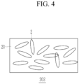
- FIG. 4 is a schematic top plan view of the non-oriented negative electrode 202 according to one or more embodiments of the present disclosure
- FIG. 5 is a schematic cross-sectional view of the non-oriented negative electrode 202 according to one or more embodiments of the present disclosure.
- oriented active material particles 2 may be erected at a certain angle with respect to the substrate 20, that is, erected in a transverse direction (e.g. , a generally or substantially vertical direction) with respect to the substrate 20.
- a carbon-based active material for example, including graphite particles each having a long length in one direction, is shown as the negative active material particles.
- the non-oriented negative electrode 202 does not undergo a separate orientation process after applying the negative active material, and thus the negative active material particles 2 are in a non-oriented state.
- the negative active material particles 2 in the non-oriented state may be aligned in not just one direction but in various directions indicated by the long axis of the negative active material particles (the central axis of the long part of the active material particles) as shown in FIG. 4 , and as shown in FIG. 5 , most of the negative active material particles may be placed in a direction that extends along ( e.g. , is parallel or substantially parallel to) one side ( e.g. , one surface) of the substrate 20.
- Some negative active material particles may be erected at a certain angle with respect to one surface of the substrate 20, but their content ( e.g. , amount) is insignificant and thus are not shown in the drawing.
- the electrode assembly 101 include the oriented negative electrode 201, the non-oriented negative electrode 202, the positive electrode 100 between the oriented negative electrode 201 and the non-oriented negative electrode 202, and the separator (e.g. , a first separator 300) between the positive electrode 100 and the oriented negative electrode 201 and ( e.g. , a second separator 300) between the positive electrode 100 and non-oriented negative electrode 202.
- the separator e.g. , a first separator 300 between the positive electrode 100 and the oriented negative electrode 201 and ( e.g. , a second separator 300) between the positive electrode 100 and non-oriented negative electrode 202.
- the oriented negative electrode 201 includes a first negative electrode active material (including a first active material layer 21) including or being in the form of particles 2 oriented in one direction, and the non-oriented negative electrode 202 include a second negative electrode active material (including a first active material layer 22) including or being in the form of particles 2 randomly oriented in one or more directions.
- the oriented negative electrode 202 includes a substrate 20 and the first negative electrode active material (or layer 22) on the substrate 20, and the particles 2 of the first negative electrode active material (or layer 22) are oriented at an angle transverse to a main side (e.g., top side) of the substrate 20.
- the x-ray diffraction (XRD) is a useful analysis method using diffraction, and is mainly used to check the crystal structure and grain size of an object, etc.
- the x-ray diffraction (XRD) analysis (002/110) of the oriented electrode 201 may have a smaller value than the XRD (002/110) of the non-oriented electrode, and, for example, the XRD (002/110) ( e.g. , the intensity ratio of the (002/110) peaks of the XRD) of the oriented electrode 201 may have a value less then or equal 200 and the XRD (002/110) ( e.g. , the intensity ratio of the (002/110) peaks of the XRD) of the non-oriented electrode may have a value exceeding 200.
- the oriented negative electrode 201 and the non-oriented negative electrode 202 may be arranged on opposite sides of the positive electrode 100 within the electrode assembly 101 and they 201, 100, 202 may be alternately and repeatedly stacked.
- the separator 300 is a polymer film that passes lithium ion, and may be polyethylene, polypropylene, polyvinylidene fluoride, or a multilayer of two or more layers thereof may be utilized, and/or mixed multilayers such as a polyethylene/polypropylene double-layered separator, a polyethylene/polypropylene/polyethylene triple-layered separator, a polypropylene/polyethylene/polypropylene triple-layered separator, and/or the like may also be utilized.
- the separator 300 is formed to be larger in size or area than that of each of the negative electrodes 201 and 202 and the positive electrode 100 and may protrude outward from the negative electrodes 201 and 202 and the positive electrode 100.
- the first electrode uncoated region S1 and the second electrode uncoated regions P1 of the repeatedly stacked positive electrode 100 and the negative electrodes 201 and 202 may be electrically connected with additional first electrode or second electrode uncoated regions S1, P1 of the same polarity, respectively, and thus may be electrically connected to outer terminals.
- the first electrode uncoated region S1 of the positive electrode 100 and the second electrode uncoated regions P2 of the negative electrodes 201 and 202 may be spaced and/or apart (e.g., spaced apart or separated) from each other and may protrude in substantially the same direction, but the present disclosure is not limited thereto and the first electrode uncoated region S1 of the positive electrode 100 and the second electrode uncoated regions P2 of the negative electrodes 201 and 202 may protrude in opposite directions.
- the electrode assembly 101 may be accommodated with an electrolyte in a pouch or can-shaped prismatic case and utilized as a rechargeable battery.
- the electrolyte may include a non-aqueous organic solvent and a lithium salt.
- the non-aqueous organic solvent serves as a medium through which ions involved in the electrochemical reaction of a battery may move.
- the lithium salt is a material that dissolves in an organic solvent and serves as a supply source of lithium ions within the battery, enabling the basic operation of the lithium secondary battery and promoting the movement of lithium ions between the positive electrode and the negative electrode.
- the lithium salt one or two or more of ( e.g. , selected from among) a group including ( e.g.
- the concentration of lithium salt be utilized within a range of 0.1M to 2.0M.
- the electrolyte has appropriate or suitable conductivity (e.g., of ions) and appropriate or suitable viscosity, and thus it may have excellent or suitable electrolyte performance and lithium ions may move effectively.
- the stress from contraction and expansion during charge and discharge can be induced to disperse stably and uniformly (substantially uniformly) by alternately stacking the oriented negative electrode 201 and the non-oriented negative electrode 202.
- FIG. 6 and FIG. 7 are provided for description of the operation of the negative electrode according to one or more embodiments of the present disclosure.
- the battery When the rechargeable battery expands due to charging and discharging, the battery may expand in a direction that is transverse (e.g. , generally or substantially perpendicular) to a lithium ion injection direction (as shown, for example, by the dotted line arrow of FIG. 6 ), and the oriented negative electrode 201 may expand in a direction that extends along ( e.g. , is parallel or substantially parallel) to a side ( e.g. , a main or top) side of the substrate 20 (as shown, for example, by the solid line right pointing arrow of FIG. 6 ) and the non-oriented negative electrode 202 may expand in direction that is transverse ( e.g. , generally or substantially perpendicular or normal) to the side of the substrate 20 (as shown, for example, by the solid line up and down pointing arrows of FIG. 7 ).
- the oriented negative electrode 201 may expand in a direction that extends along ( e.g. , is parallel or substantially parallel) to
- the oriented negative electrode 201 is configured to expand in a direction parallel the side of the substrate 20, and the non-oriented negative electrode 202 is configured to expand in a transverse or normal direction with respect to the side of the substrate 20 ( e.g. , expand in thickness direction of the substrate 20).
- the oriented negative electrode and the non-oriented negative electrode are alternately arranged and thus the horizontal expansion and the transverse (e.g. , generally or substantially vertical) expansion occur alternately within the electrode assembly such that stress can be dispersed rather than being concentrated in any one place in the entire electrode assembly.
- Table 1 is a table of measurement of charging and discharging characteristics according to an Embodiment of the present disclosure and Comparative Examples.
- Cell type or kind Formation process charge and discharge process
- Cell thickness deviation of position-specific to entire average value Room temperature lifespan Initial efficiency 1 2 3 4 5 @120cy.
- Comparative Example 1 86.9 % 1.85 % -0.81 % -0.62 % -1.30 % 0.88 % 93.4 %
- Comparative Example 2 87.1 % -1.08 % 0.77 % 0.94 % 0.61 % -1.24 % 94.1 %
- Embodiment 87.9 % 0.48 % -0.18 % -0.06 % 0.04 % -0.29 % 94.5 %
- Comparative Example 1 and Comparative Example 2 are electrode assemblies according to the related or comparative art, and Comparative Example 1 is a non-oriented electrode assembly in which an orientation process is not performed on an active material layer and Comparative Example 2 is an oriented electrode assembly in which the orientation process is performed on the entire active material layer, and the Embodiment is an electrode assembly according to one or more embodiments of the present disclosure and includes oriented and non-oriented active materials. Conditions not presented in Table 1 can be understood to be the same between Comparative Examples 1 and 2 and the Embodiment.
- the electrode assemblies according to Comparative Examples 1 and 2 and Embodiment are electrode assemblies with 2,100 mAh charge capacity, and measurement was carried out with cycles of CC/CV 0.5C-4.2V, 0.2C cut-off, and 10 minutes rest during charging, and CC 0.5C-2.80V cut-off and 10 minutes rest during discharging.
- Embodiment showed an improvement in initial efficiency of 87.9 % during the chemical process, compared to 86.9 % in Comparative Example 1 and 87.1 % in Comparative Example 2.
- the Embodiment had an efficiency of 94.5 % and Comparative Examples 1 and 2 had an efficiency of 93.4 % and 94.1 %, respectively, showing that the efficiency after 120 repetitions is higher in the Embodiment.
- a cell thickness was measured in five different regions of the electrode assembly. Regions 1 and 5 are both edges of each electrode assembly, and regions 2, 3, and 4 are located in the middle between regions 1 and 5, with reference to the transverse cross-section of the electrode assembly.
- Comparative Example 1 When compared to the average value of thickness measured in the plurality of regions, Comparative Example 1 had a thickness deviation of 0.62% to 1.85%, Comparative Example 2 had a thickness deviation of 0.61% to 1.24%, while the Embodiment had a thickness deviation of 0.04% to 0.48%. Accordingly, it can be observed that the thickness deviation is relatively and substantially small in the Embodiment.
- the thickness deviation in each region is less in the Embodiment than in Comparative Examples 1 and 2.
- FIG. 8 is a graph that shows the average of the actual cell thickness in the Embodiment and Comparative Examples.
- the regions 1, 2, 3, 4, and 5 almost had the same thickness in the Embodiment, but in Comparative Examples 1 and 2, the regions 2, 3, and 4 positioned in the middle were thicker than the regions 1 and 5 positioned at the edges, showing that thickness deviation occurred at the edge and the center.
- an electrode assembly with reduced thickness deviation and improved lifespan characteristic can be manufactured by alternately arranging the oriented electrode and the non-oriented electrode as in one or more embodiments of the present disclosure.
- FIG. 9 schematically illustrates an electrode assembly according to one or more embodiments of the present disclosure.
- An electrode assembly of FIG. 9 is almost the same as (e.g., is substantially similar to) the electrode assembly of FIG. 1 , and therefore only substantial differences will be described in more detail.
- a positive electrode 100 and negative electrodes 201 and 202 are alternatively stacked while disposing a separator 300 therebetween, an oriented negative electrode 201 and a non-oriented negative electrode 202 may be arranged opposite to each other, while disposing the positive electrode 100 therebetween.
- an accommodation portion in which each of the negative electrodes 201 and 202 are inserted and around ( e.g. , surrounding) the entire negative electrodes 201 and 202 including edges may be formed by the separator 300, and the accommodation portion is larger than the volume of the negative electrodes 201 and 202 such that the negative electrodes 201 and 202 can be easily accommodated therein.
- the separator 300 may be formed as substantially continuous one or may have a repeatedly folded shape.
- the positive electrode 100 may be arranged between one accommodation portion and another accommodation portion of the separator 300.
- the term “substantially,” “about,” and similar terms are used as terms of approximation and not as terms of degree, and are intended to account for the inherent deviations in measured or calculated values that would be recognized by those of ordinary skill in the art. "Substantially” as used herein, is inclusive of the stated value and means within an acceptable range of deviation for the particular value as determined by one of ordinary skill in the art, considering the measurement in question and the error associated with measurement of the particular quantity (i.e., the limitations of the measurement system). For example, “substantially” may mean within one or more standard deviations, or within ⁇ 30%, 20%, 10%, 5% of the stated value.
- any numerical range recited herein is intended to include all subranges of the same numerical precision subsumed within the recited range.
- a range of "1.0 to 10.0" is intended to include all subranges between (and including) the recited minimum value of 1.0 and the recited maximum value of 10.0, that is, having a minimum value equal to or greater than 1.0 and a maximum value equal to or less than 10.0, such as, for example, 2.4 to 7.6.
- Any maximum numerical limitation recited herein is intended to include all lower numerical limitations subsumed therein and any minimum numerical limitation recited in this specification is intended to include all higher numerical limitations subsumed therein. Accordingly, Applicant reserves the right to amend this specification, including the claims, to expressly recite any sub-range subsumed within the ranges expressly recited herein.
- the portable device, vehicle, and/or the battery e.g., a battery controller, and/or any other relevant devices or components according to embodiments of the present disclosure described herein may be implemented utilizing any suitable hardware, firmware (e.g. , an application-specific integrated circuit), software, or a combination of software, firmware, and hardware.
- the various components of the device may be formed on one integrated circuit (IC) chip or on separate IC chips.
- the various components of the device may be implemented on a flexible printed circuit film, a tape carrier package (TCP), a printed circuit board (PCB), or formed on one substrate.
- the various components of the device may be a process or thread, running on one or more processors, in one or more computing devices, executing computer program instructions and interacting with other system components for performing the various functionalities described herein.
- the computer program instructions are stored in a memory which may be implemented in a computing device using a standard memory device, such as, for example, a random access memory (RAM).
- the computer program instructions may also be stored in other non-transitory computer readable media such as, for example, a CD-ROM, flash drive, or the like.
Landscapes
- Chemical & Material Sciences (AREA)
- Chemical Kinetics & Catalysis (AREA)
- Electrochemistry (AREA)
- General Chemical & Material Sciences (AREA)
- Engineering & Computer Science (AREA)
- Materials Engineering (AREA)
- Manufacturing & Machinery (AREA)
- Inorganic Chemistry (AREA)
- Battery Electrode And Active Subsutance (AREA)
- Secondary Cells (AREA)
Applications Claiming Priority (1)
| Application Number | Priority Date | Filing Date | Title |
|---|---|---|---|
| KR1020230147199A KR20250062341A (ko) | 2023-10-30 | 2023-10-30 | 전극 조립체 및 이를 포함하는 이차 전지 |
Publications (1)
| Publication Number | Publication Date |
|---|---|
| EP4550476A1 true EP4550476A1 (de) | 2025-05-07 |
Family
ID=92925408
Family Applications (1)
| Application Number | Title | Priority Date | Filing Date |
|---|---|---|---|
| EP24203006.2A Pending EP4550476A1 (de) | 2023-10-30 | 2024-09-26 | Elektrodenanordnung und wiederaufladbare batterie damit |
Country Status (3)
| Country | Link |
|---|---|
| US (1) | US20250140783A1 (de) |
| EP (1) | EP4550476A1 (de) |
| KR (1) | KR20250062341A (de) |
Citations (4)
| Publication number | Priority date | Publication date | Assignee | Title |
|---|---|---|---|---|
| JP2016066426A (ja) * | 2014-09-23 | 2016-04-28 | トヨタ自動車株式会社 | 非水電解液二次電池 |
| EP3316378A1 (de) * | 2016-11-01 | 2018-05-02 | Samsung SDI Co., Ltd. | Negative elektrode beinhaltend teilweise ausgerichtetes graphit auf stromsammler für wiederaufladbare lithiumbatterie, sowie wiederaufladbare lithiumbatterie |
| US11152606B2 (en) * | 2016-11-29 | 2021-10-19 | Samsung Sdi Co., Ltd. | Electrode assembly and rechargeable battery including the same |
| JP2023069760A (ja) * | 2021-11-08 | 2023-05-18 | 株式会社村田製作所 | 二次電池用の負極およびその製造方法 |
-
2023
- 2023-10-30 KR KR1020230147199A patent/KR20250062341A/ko active Pending
-
2024
- 2024-03-29 US US18/622,313 patent/US20250140783A1/en active Pending
- 2024-09-26 EP EP24203006.2A patent/EP4550476A1/de active Pending
Patent Citations (4)
| Publication number | Priority date | Publication date | Assignee | Title |
|---|---|---|---|---|
| JP2016066426A (ja) * | 2014-09-23 | 2016-04-28 | トヨタ自動車株式会社 | 非水電解液二次電池 |
| EP3316378A1 (de) * | 2016-11-01 | 2018-05-02 | Samsung SDI Co., Ltd. | Negative elektrode beinhaltend teilweise ausgerichtetes graphit auf stromsammler für wiederaufladbare lithiumbatterie, sowie wiederaufladbare lithiumbatterie |
| US11152606B2 (en) * | 2016-11-29 | 2021-10-19 | Samsung Sdi Co., Ltd. | Electrode assembly and rechargeable battery including the same |
| JP2023069760A (ja) * | 2021-11-08 | 2023-05-18 | 株式会社村田製作所 | 二次電池用の負極およびその製造方法 |
Also Published As
| Publication number | Publication date |
|---|---|
| US20250140783A1 (en) | 2025-05-01 |
| KR20250062341A (ko) | 2025-05-08 |
Similar Documents
| Publication | Publication Date | Title |
|---|---|---|
| US11295901B2 (en) | Hybrid electrode materials for bipolar capacitor-assisted solid-state batteries | |
| US10396398B2 (en) | Secondary battery | |
| CN108123180B (zh) | 电极组件和包括其的可再充电电池 | |
| US20230187637A1 (en) | Electrode, lithium battery including the same, and method of manufacturing the electrode | |
| US20060197496A1 (en) | Combination of lithium ion batteries | |
| US11127946B2 (en) | Negative electrode for rechargeable battery and rechargeable battery including the same | |
| CN108172751A (zh) | 可再充电电池的负极及其制造方法 | |
| US20230085771A1 (en) | Electrode, lithium battery containing electrode, and preparation method thereof | |
| CN102576870A (zh) | 电气装置用正极材料及使用其的电气装置 | |
| US20230246202A1 (en) | Electrode, lithium battery including the same, and method of preparing the electrode | |
| KR102467458B1 (ko) | 리튬 이차 전지 | |
| US20190131623A1 (en) | Method for charging lithium-ion secondary battery, lithium-ion secondary battery system, and power storage device | |
| CN110024184B (zh) | 用于可再充电电池的负极和包括其的可再充电电池 | |
| US20240322120A1 (en) | Method of preparing dry electrode, device for manufacturing dry electrode, dry electrode, and lithium battery | |
| KR102687648B1 (ko) | 리튬 이차 전지 | |
| KR102510889B1 (ko) | 리튬 이차전지용 양극, 이의 제조방법 및 이를 포함한 리튬 이차전지 | |
| KR20220036072A (ko) | 리튬 이차 전지용 양극 활물질 및 이를 포함하는 리튬 이차 전지 | |
| JPH11162467A (ja) | 非水系二次電池 | |
| US20240322118A1 (en) | Dry electrode and lithium battery including the same | |
| EP4550476A1 (de) | Elektrodenanordnung und wiederaufladbare batterie damit | |
| KR102195725B1 (ko) | 리튬 이차전지용 양극, 이의 제조방법 및 이를 포함한 리튬 이차전지 | |
| KR20150012883A (ko) | 리튬 이차전지용 양극 및 이를 포함하는 리튬 이차전지 | |
| KR20230065076A (ko) | 복합 조성의 전극 활물질, 이의 제조방법 및 이를 포함하는 전극 및 이차전지 | |
| US20250167202A1 (en) | Electrode for secondary battery and method of manufacturing the same | |
| JP2000340217A (ja) | 電極材の搬送装置、二次電池の製造装置および二次電池の製造方法 |
Legal Events
| Date | Code | Title | Description |
|---|---|---|---|
| PUAI | Public reference made under article 153(3) epc to a published international application that has entered the european phase |
Free format text: ORIGINAL CODE: 0009012 |
|
| STAA | Information on the status of an ep patent application or granted ep patent |
Free format text: STATUS: REQUEST FOR EXAMINATION WAS MADE |
|
| 17P | Request for examination filed |
Effective date: 20240926 |
|
| AK | Designated contracting states |
Kind code of ref document: A1 Designated state(s): AL AT BE BG CH CY CZ DE DK EE ES FI FR GB GR HR HU IE IS IT LI LT LU LV MC ME MK MT NL NO PL PT RO RS SE SI SK SM TR |