EP4550512A1 - Procédé de fabrication d'ensemble électrode à aptitude au traitement améliorée, et ensemble électrode ainsi fabriqué - Google Patents
Procédé de fabrication d'ensemble électrode à aptitude au traitement améliorée, et ensemble électrode ainsi fabriqué Download PDFInfo
- Publication number
- EP4550512A1 EP4550512A1 EP23880120.3A EP23880120A EP4550512A1 EP 4550512 A1 EP4550512 A1 EP 4550512A1 EP 23880120 A EP23880120 A EP 23880120A EP 4550512 A1 EP4550512 A1 EP 4550512A1
- Authority
- EP
- European Patent Office
- Prior art keywords
- sheet
- negative electrode
- positive electrode
- electrode sheet
- electrode
- Prior art date
- Legal status (The legal status is an assumption and is not a legal conclusion. Google has not performed a legal analysis and makes no representation as to the accuracy of the status listed.)
- Pending
Links
Images


Classifications
-
- H—ELECTRICITY
- H01—ELECTRIC ELEMENTS
- H01M—PROCESSES OR MEANS, e.g. BATTERIES, FOR THE DIRECT CONVERSION OF CHEMICAL ENERGY INTO ELECTRICAL ENERGY
- H01M10/00—Secondary cells; Manufacture thereof
- H01M10/05—Accumulators with non-aqueous electrolyte
- H01M10/058—Construction or manufacture
- H01M10/0585—Construction or manufacture of accumulators having only flat construction elements, i.e. flat positive electrodes, flat negative electrodes and flat separators
-
- H—ELECTRICITY
- H01—ELECTRIC ELEMENTS
- H01M—PROCESSES OR MEANS, e.g. BATTERIES, FOR THE DIRECT CONVERSION OF CHEMICAL ENERGY INTO ELECTRICAL ENERGY
- H01M4/00—Electrodes
- H01M4/02—Electrodes composed of, or comprising, active material
- H01M4/04—Processes of manufacture in general
- H01M4/0402—Methods of deposition of the material
- H01M4/0404—Methods of deposition of the material by coating on electrode collectors
-
- H—ELECTRICITY
- H01—ELECTRIC ELEMENTS
- H01M—PROCESSES OR MEANS, e.g. BATTERIES, FOR THE DIRECT CONVERSION OF CHEMICAL ENERGY INTO ELECTRICAL ENERGY
- H01M10/00—Secondary cells; Manufacture thereof
- H01M10/04—Construction or manufacture in general
- H01M10/0404—Machines for assembling batteries
-
- H—ELECTRICITY
- H01—ELECTRIC ELEMENTS
- H01M—PROCESSES OR MEANS, e.g. BATTERIES, FOR THE DIRECT CONVERSION OF CHEMICAL ENERGY INTO ELECTRICAL ENERGY
- H01M10/00—Secondary cells; Manufacture thereof
- H01M10/05—Accumulators with non-aqueous electrolyte
- H01M10/052—Li-accumulators
-
- H—ELECTRICITY
- H01—ELECTRIC ELEMENTS
- H01M—PROCESSES OR MEANS, e.g. BATTERIES, FOR THE DIRECT CONVERSION OF CHEMICAL ENERGY INTO ELECTRICAL ENERGY
- H01M4/00—Electrodes
- H01M4/02—Electrodes composed of, or comprising, active material
- H01M4/04—Processes of manufacture in general
- H01M4/043—Processes of manufacture in general involving compressing or compaction
- H01M4/0435—Rolling or calendering
-
- H—ELECTRICITY
- H01—ELECTRIC ELEMENTS
- H01M—PROCESSES OR MEANS, e.g. BATTERIES, FOR THE DIRECT CONVERSION OF CHEMICAL ENERGY INTO ELECTRICAL ENERGY
- H01M4/00—Electrodes
- H01M4/02—Electrodes composed of, or comprising, active material
- H01M4/13—Electrodes for accumulators with non-aqueous electrolyte, e.g. for lithium-accumulators; Processes of manufacture thereof
- H01M4/134—Electrodes based on metals, Si or alloys
-
- H—ELECTRICITY
- H01—ELECTRIC ELEMENTS
- H01M—PROCESSES OR MEANS, e.g. BATTERIES, FOR THE DIRECT CONVERSION OF CHEMICAL ENERGY INTO ELECTRICAL ENERGY
- H01M4/00—Electrodes
- H01M4/02—Electrodes composed of, or comprising, active material
- H01M4/13—Electrodes for accumulators with non-aqueous electrolyte, e.g. for lithium-accumulators; Processes of manufacture thereof
- H01M4/139—Processes of manufacture
-
- H—ELECTRICITY
- H01—ELECTRIC ELEMENTS
- H01M—PROCESSES OR MEANS, e.g. BATTERIES, FOR THE DIRECT CONVERSION OF CHEMICAL ENERGY INTO ELECTRICAL ENERGY
- H01M4/00—Electrodes
- H01M4/02—Electrodes composed of, or comprising, active material
- H01M4/62—Selection of inactive substances as ingredients for active masses, e.g. binders, fillers
- H01M4/621—Binders
- H01M4/622—Binders being polymers
-
- Y—GENERAL TAGGING OF NEW TECHNOLOGICAL DEVELOPMENTS; GENERAL TAGGING OF CROSS-SECTIONAL TECHNOLOGIES SPANNING OVER SEVERAL SECTIONS OF THE IPC; TECHNICAL SUBJECTS COVERED BY FORMER USPC CROSS-REFERENCE ART COLLECTIONS [XRACs] AND DIGESTS
- Y02—TECHNOLOGIES OR APPLICATIONS FOR MITIGATION OR ADAPTATION AGAINST CLIMATE CHANGE
- Y02E—REDUCTION OF GREENHOUSE GAS [GHG] EMISSIONS, RELATED TO ENERGY GENERATION, TRANSMISSION OR DISTRIBUTION
- Y02E60/00—Enabling technologies; Technologies with a potential or indirect contribution to GHG emissions mitigation
- Y02E60/10—Energy storage using batteries
-
- Y—GENERAL TAGGING OF NEW TECHNOLOGICAL DEVELOPMENTS; GENERAL TAGGING OF CROSS-SECTIONAL TECHNOLOGIES SPANNING OVER SEVERAL SECTIONS OF THE IPC; TECHNICAL SUBJECTS COVERED BY FORMER USPC CROSS-REFERENCE ART COLLECTIONS [XRACs] AND DIGESTS
- Y02—TECHNOLOGIES OR APPLICATIONS FOR MITIGATION OR ADAPTATION AGAINST CLIMATE CHANGE
- Y02P—CLIMATE CHANGE MITIGATION TECHNOLOGIES IN THE PRODUCTION OR PROCESSING OF GOODS
- Y02P70/00—Climate change mitigation technologies in the production process for final industrial or consumer products
- Y02P70/50—Manufacturing or production processes characterised by the final manufactured product
Definitions
- the present disclosure relates to a method of manufacturing an electrode assembly and an electrode assembly manufactured by using the same, and more particularly, to a method of manufacturing an electrode assembly having improved processability and an electrode assembly manufactured by using the same.
- a secondary battery has attracted considerable attention as an energy source for power-driven devices, such as an electric bicycle, an electric vehicle, and a hybrid electric vehicle, as well as an energy source for mobile devices, such as a mobile phone, a digital camera, a laptop computer and a wearable device.
- Such a lithium secondary battery is manufactured by embedding an electrode assembly together with an electrolyte in a battery case, wherein the electrode assembly is obtained by coating a positive electrode or an negative electrode active material, a binder and a conductive material on a current collector in the form of a slurry and drying them to form an electrode mixture layer, thereby manufacturing a positive electrode and an negative electrode, interposing a separator between the positive electrode and the negative electrode, and then laminating them.
- a stacked/folded type electrode assembly which is configured to have a structure in which full cells having a positive electrode/separator/negative electrode structure of a certain unit size or bi-cells having a positive electrode(negative electrode)/separator/negative electrode(positive electrode)/separator/positive electrode(negative electrode) structure are folded using a long continuous separator film, has been developed as an electrode assembly having an advanced structure that is a combination of a jelly-roll type and a stack type.
- a laminated and stacked type electrode assembly which is configured to have a structure in which unit cells in which electrodes and separators are alternately laminated and joined has also been developed in order to improve processability of a conventional stacked type electrode assembly and to satisfy demand for various kinds of secondary batteries.
- a stacked type electrode assembly When manufacturing a stacked type electrode assembly, it is generally manufactured by a lamination method in which a positive electrode, a separator and an negative electrode are respectively produced in separate processes, then laminated and joined by applying heat and pressure at the same time. At this time, a punching process may be performed to realize the shape of the electrode assembly before joining the electrode and the separator by the lamination method. In the punching process, the positive electrode and the negative electrode are individually punched, and then laminated together with a separator to manufacture a stacked type electrode assembly by a lamination method.
- the separator may be cut in a larger quantity than the positive electrode and negative electrode during the punching process and then laminated, but if that is the case, the production unit costs may increase because the separator is cut in a larger quantity than needed.
- a method of manufacturing an electrode assembly comprising the steps of: unwinding a positive electrode sheet, a separator sheet and an negative electrode sheet from a plurality of roll members, respectively, forming a laminate while passing the unwound positive electrode sheet, separator sheet, and negative electrode sheet between a pair of guide rolls, and punching the laminate including the positive electrode sheet, the separator sheet, and the negative electrode sheet, wherein each of the positive electrode sheet and the negative electrode sheet is alternately coated with an active material and a non-conductive material based on a traveling direction of the guide rolls, and wherein the punching the laminate punches a portion coated with the non-conductive material.
- the step of punching the laminate may punch the positive electrode sheet, the separator sheet, and the negative electrode sheet at the same time.
- the negative electrode sheet may be formed to include lithium metal.
- a marker part for guiding a punching position of the laminate may be formed in a portion coated with the non-conductive material.
- the marker part may be formed on the same line as the line on which the non-conductive material is coated during the process of coating the non-conductive material.
- the non-conductive material may include a polymer material.
- the polymer material used may be PE (polyethylene) series.
- the step of alternately coating the active material and the non-conductive material onto each of the positive electrode sheet and the negative electrode sheet may be performed before unwinding a positive electrode sheet and an negative electrode sheet from the roll members.
- the step of passing through the guide roll to form the laminate may be performed immediately after the unwinding the positive electrode sheet, the separator sheet, and the negative electrode sheet from the plurality of roll members, respectively.
- the step of punching the laminate uses a cutting member, wherein the non-conductive material is formed of a material having ductility to ensure that an electrode material does not adhere to the cutting member.
- the direction in which the laminate is punched may be perpendicular to the traveling direction of the guide rolls.
- an electrode assembly manufactured by the method of manufacturing the electrode assembly described above, the electrode assembly includes a positive electrode, a separator, and an negative electrode formed after the laminate is punched, and the positive electrode and the negative electrode each include an active material layer and a non-conductive layer located on both sides of the active material layer.
- each of the positive electrode, the separator, and the negative electrode may be equal to each other based on a direction that is perpendicular to a direction in which an electrode tab of the positive electrode or the negative electrode protrudes and is perpendicular to the preset direction.
- the widths of the positive electrode active material layer and the negative electrode active material layer included respectively in the positive electrode and the negative electrode may be equal to each other based on a direction perpendicular to the direction in which the electrode tab protrudes.
- the positive electrode sheet/separator/negative electrode sheet are unwound at the same time, and then punched at the same time, thereby making it possible to reduce the complexity of the punching and lamination process.
- a non-conductive layer is formed at both ends of the positive electrode/negative electrode, thereby making it possible to prevent a phenomenon of short circuits at the side surfaces.
- the cutting member directly contacts the electrode material during the punching process, thereby preventing the electrode material adhering to the cutting member from contaminating electrodes having different polarities.
- a marker part is formed on the non-conductive layer, thereby making it possible to accurately set the punching position during the process and increase production yield.
- the electrode assembly manufacturing apparatus includes a plurality of roll members 100, 200 and 300, and includes a transfer member (not shown) that transfers the sheets 110, 210 and 310 unwound from a plurality of roll members 100, 200 and 300, respectively, a pair of guide rolls 400 that guide a plurality of sheets 110, 210 and 310, and a cutting member 500 that punches a plurality of sheets 110, 210 and 310.
- the negative electrode sheet 310 is also in a non-punched state, and may be wound around the third winding roll 300 in the form of a sheet extending long in one direction in a state where an negative electrode active material layer and a non-conductive layer are formed on the negative electrode current collector, as described later.
- the transport member may be a conveyor belt unit, and may serve to transport the sheets 110, 210 and 310 in one direction (x-axis direction).
- the guide rolls 400 include an upper guide roll 410 and a lower guide roll 420 that are arranged separately on upper and lower parts, and the sheets 110, 210, and 310 can pass between the rolls.
- the cutting member 500 may be a punching knife that directly cuts the positive electrode sheet 110, the separator sheet 210, and the negative electrode sheet 310.
- the cutting member 500 may cut the sheets 110, 210 and 310 in a direction perpendicular to the first direction (x-axis direction) in which the sheets 110, 210 and 310 are transferred.
- the positive electrode sheet 110, the separator sheet 210, and the negative electrode sheet 310 are each unwound from the plurality of roll members 100, 200 and 300 and transferred along the first direction (x-axis direction), and then while being unwound, the positive electrode sheet 110, the separator sheet 210, and the negative electrode sheet 310 may be in close contact with each other in a direction perpendicular to the transfer direction (x-axis direction). In other words, the sheets 110, 210 and 310 may be unwound from the plurality of roll members 100, 200 and 300 to be in a laminated state.
- the unwound positive electrode sheet 110, separator sheet 210, and negative electrode sheet 310 may form a laminate while passing between a pair of guide rolls 400.
- the sheets 110, 210 and 310 made in a laminate shape can pass between an upper guide roll 410 and a lower guide roll 420, which are arranged separately on upper and lower parts.
- the step of passing through the guide rolls 400 to form the laminate may be preferably performed immediately after the step of unwinding the positive electrode sheet 110, the separator sheet 210 and the negative electrode sheet 310 from the plurality of roll members 100, 200 and 300, respectively.
- the laminate formed by passing between a pair of guide rolls 420 can still maintain a continuous sheet shape. Further, the sheets 110, 210, and 310, which have been unwound to form a laminated state, can pass between the pair of guide rolls 420 and further closely adhere to each other to forming a laminate. Then, the sheets 110, 210 and 310 may be transferred in the first direction (x-axis direction) and maintained in a laminated state. Then, a lamination process may be performed in which heat and pressure are applied so that the positive electrode sheet 110, the separator sheet 210, and the negative electrode sheet 310 are joined to each other.
- FIG. 2 schematically shows portions punched by the cutting member 500 after the plurality of sheets 110, 210 and 310 pass through a pair of guide rolls 400.
- the laminate including the positive electrode sheet 110, the separator sheet 210, and the negative electrode sheet 310 may be punched using a cutting member 500.
- the cutting member 500 can directly cut the positive electrode sheet 110, the separator sheet 210, and the negative electrode sheet 310.
- a coated part on which the active material layer 111 is formed and an uncoated part 112 that is not coated with an active material may be located on the positive electrode sheet 110 along a direction perpendicular to the traveling direction of the guide roll 400 (y-axis direction).
- the coated part and the uncoated part 112 may be sequentially arranged in the -y-axis direction.
- the active material layer 111 may be a positive electrode mixture layer including a positive electrode active material, a binder, and a conductive material.
- a coated part in which the active material layer 311 is formed and an uncoated part 312 that is not coated with the active material may be located on the negative electrode sheet 310 along a direction perpendicular to the traveling direction of the guide roll 400 (y-axis direction).
- the coated part and the uncoated part 312 may be sequentially arranged in the y-axis direction.
- the active material layer 311 may be an negative electrode mixture layer including an negative electrode active material, a binder and a conductive material.
- the active material layer 311 can be formed by coating and drying an negative electrode active material, a binder, and a conductive material in the form of a slurry on a current collector.
- the uncoated parts 112 and 312 formed respectively on the positive electrode sheet 110 and the negative electrode sheet 310 may be arranged in different directions from each other with respect to the coated part.
- the tab-shaped protrusions formed respectively on the positive electrode sheet 110 and the negative electrode sheet 310 may be arranged in different directions from each other with respect to the coated part.
- the tab-shaped protrusion can be used as an electrode tab.
- the uncoated parts 112 and 312 can be used as electrode tabs as they are, and as another example, the tab-shaped protrusion may have a shape that allows separate electrode tabs to easily attach thereto.
- FIG. 3 shows a state in which the positive electrode sheet 110, the separator sheet 210, and the negative electrode sheet 310, which are overlapped in the vertical direction (z-axis direction in FIG. 1 ) in the process of punching the laminate, are separated in a plane when viewed along the z-axis direction.
- each of the positive electrode sheet 110 and the negative electrode sheet 310 may be in a state in which the active material and the non-conductive material are alternately coated based on the traveling direction (x-axis direction) of the guide roll 400.
- the step of alternately coating the active material and the non-conductive material onto each of the positive electrode sheet 110 and the negative electrode sheet 310 may be performed before the step of unwinding the positive electrode sheet 110 and the negative electrode sheet 310 from the roll members 100 and 300.
- the positive electrode sheet 110, the separator sheet 210, and the negative electrode sheet 310 may be punched at the same time.
- the direction in which the laminate is punched may be a direction perpendicular to the traveling direction (z-axis direction in FIG. 1 ) of the guide roll 400.
- the positive electrode sheet 110, the separator sheet 210, and the negative electrode sheet 310 are punched at the same time, it is possible to solve the problem that the assembly process time becomes longer and the cost increases when manufacturing a stacked type electrode assembly by punching the electrodes and the separator individually and then laminating them as in the past.
- an electrode material may adhere onto the cutting member 500. While the sheets 110, 210, and 310 travel, the laminate is punched at regular intervals. However, if the laminate is cut in a state where the electrode material adhere onto the cutting member 500, the electrode material may come into contact with an electrode sheet having a polarity different from that of the electrode material adhered onto the cutting member 500. If that is the case, the quality of the electrode may deteriorate and ultimately the life of the battery decreases.
- the electrode part coated with the non-conductive material is punched.
- the cutting member 500 of FIG. 2 can cut the laminate along the punching position line 610 that crosses the non-conductive layers 113 and 313.
- a marker part 600 that guides the punching position of the laminate may be formed on the portion coated with the non-conductive material.
- the marker part 600 may be formed on the same line as the line on which the non-conductive material is coated during the process of coating the non-conductive material. In other words, as shown in FIG. 3 , it is preferable that the marker part 600 is formed substantially on the same line as the punching position line 610.
- the non-conductive material coating device and the marker part forming device can be linked to leave a marker at the central position of the portion where the non-conductive material is coated, thereby forming a marker part 600.
- the punching position of the cutting member 500 can be found more accurately during an automated process, and thereby the effect of improving production yield can be expected.
- the marker unit 600 according to the present embodiment may perform not only the role of accurately finding the punching position, but also the role of aligning the positive electrode sheet 110, the separator sheet 210 and the negative electrode sheet 310 when unwinding them from a plurality of reel members 100, 200 and 300.
- the positive electrode sheet 110 may have an active material layer 111 and a non-conductive layer 113 formed on at least one surface of the positive electrode current collector 115
- the negative electrode sheet 310 may have an active material layer 311 and a non-conductive layer 313 formed on at least one surface of the negative electrode current collector 315.
- the cutting member 500 of FIG. 2 cuts the laminate in the vertical direction (z-axis direction) along the punching position line 610, so that the non-conductive layer 113 of the positive electrode sheet 110, the separator sheet 210, and the non-conductive layer 313 of the negative electrode sheet 310 are punched at the same time.
- the left and right widths of the cutting member 500 may correspond to the interval between the punching position lines 610 adjacent to each other.
- the non-conductive material forming the non-conductive layer 313 according to the present embodiment preferably includes a polymer material.
- PE polyethylene
- any polymer material with high ductility can be used. It is preferable that the non-conductive material according to the present embodiment has greater ductility than ceramics and greater ductility than common metal materials.
- the non-conductive material may have ductility similar to that of lithium metal having high ductility.
- the negative electrode sheet 310 is preferably formed from lithium metal.
- Carbon-based materials, silicon, lithium metal, and the like are used as negative electrode active materials in lithium-ion batteries, among which lithium metal has the advantage of being able to obtain the highest energy density.
- lithium metal battery is used in this way, due to the high reactivity of lithium metal, the volumetric expansion of the negative electrode during battery charging and discharging, and the surface unevenness phenomenon that occurs during the process of electrodeposition and peeling off of lithium metal from the negative electrode, a stable interface is not formed between the electrolyte and the lithium metal electrode, and a sustained electrolyte decomposition reaction can occur. Such electrolyte side reactions can shorten battery life while rapidly increasing battery resistance.
- the non-conductive layers 113 and 313 are formed using a polymer material having high ductility, the non-conductive layers 113 and 313 do not break even under strong pressure conditions, which may not cause damage to the current collectors 115 and 315. If the non-conductive layers 113 and 313 are made of a material with low ductility such as ceramic, they may break under strong pressure conditions.
- the unit cell 700 can be formed by the method for manufacturing an electrode assembly described above.
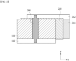
- the unit cell 700 includes a positive electrode 118, a separator 218, and an negative electrode 318, which are formed after the laminate is punched.
- the positive electrode 118 and the negative electrode 318 respectively include active material layers 111 and 311, and non-conductive layers 113 and 313 located on both sides of the active material layers 111 and 311.
- the widths of the positive electrode 118, the separator 218, and the negative electrode 318 are substantially equal to each other based on the traveling direction (x-axis direction) of the guide rolls 400 in FIG. 1 .
- the traveling direction (x-axis direction) of the guide roll 400 is perpendicular to the direction (y-axis direction) in which the electrode tab 116 of FIG. 5 protrudes, and the widths of the positive electrode 118, separator 218, and negative electrode 318 described above may be substantially equal to each other based on the direction in which the electrode tab 116 protrudes.
- the widths of the positive electrode active material layer 111 and the negative electrode active material layer 311 included respectively in the positive electrode 118 and the negative electrode 318 may be equal to each other based on the traveling direction (x-axis direction) of the guide roll 400 in FIG. 1 .
- the separator 21 is cut larger than the negative electrode 31 and the positive electrode 11 during the punching process.
- the short circuit phenomenon can be prevented because the non-conductive layers 113 and 313 are formed.
- a phenomenon when punching is performed in the laminated state, a phenomenon may occur where at least one of the plurality of sheets is pushed, but the non-conductive layers 113 and 313 can cover the portion where the positive electrode 118 and the negative electrode 318 can come into contact with each other, thereby preventing a short circuit phenomenon.
- the unit cells 700 of FIG. 5 formed after simultaneously punching the positive electrode sheet 110, the separator sheet 210, and the negative electrode sheet 310 in the laminated state can be transported and laminated by a pick & place method to form an electrode assembly.
- the unit cells 700 formed by punching a laminate may be loaded and stored in a storage box such as a magazine. Thereafter, the unit cells 700 stored in the storage box can be transported and laminated again by a pick and place method to form an electrode assembly.
- a battery cell can be manufactured by embedding an electrode assembly including at least one unit cell 700 in a battery case together with an electrolyte.
- a winding roll that winds the separator sheet is arranged below the third winding roll 300 in FIG. 1 , and when unwinding together with the positive electrode sheet 110,the separator sheet 210 and the negative electrode sheet 310, and forming the laminate according to the present embodiment described above, one end of the basic unit may be disposed so as to be a separator.
Landscapes
- Chemical & Material Sciences (AREA)
- Engineering & Computer Science (AREA)
- Chemical Kinetics & Catalysis (AREA)
- Electrochemistry (AREA)
- General Chemical & Material Sciences (AREA)
- Manufacturing & Machinery (AREA)
- Materials Engineering (AREA)
- Secondary Cells (AREA)
- Battery Electrode And Active Subsutance (AREA)
Applications Claiming Priority (2)
| Application Number | Priority Date | Filing Date | Title |
|---|---|---|---|
| KR1020220135189A KR20240054791A (ko) | 2022-10-19 | 2022-10-19 | 공정성이 개선된 전극 조립체 제조 방법 및 이를 사용하여 제조된 전극 조립체 |
| PCT/KR2023/015784 WO2024085542A1 (fr) | 2022-10-19 | 2023-10-13 | Procédé de fabrication d'ensemble électrode à aptitude au traitement améliorée, et ensemble électrode ainsi fabriqué |
Publications (2)
| Publication Number | Publication Date |
|---|---|
| EP4550512A1 true EP4550512A1 (fr) | 2025-05-07 |
| EP4550512A4 EP4550512A4 (fr) | 2025-10-15 |
Family
ID=90738074
Family Applications (1)
| Application Number | Title | Priority Date | Filing Date |
|---|---|---|---|
| EP23880120.3A Pending EP4550512A4 (fr) | 2022-10-19 | 2023-10-13 | Procédé de fabrication d'ensemble électrode à aptitude au traitement améliorée, et ensemble électrode ainsi fabriqué |
Country Status (5)
| Country | Link |
|---|---|
| EP (1) | EP4550512A4 (fr) |
| JP (1) | JP2025525171A (fr) |
| KR (1) | KR20240054791A (fr) |
| CN (1) | CN119923740A (fr) |
| WO (1) | WO2024085542A1 (fr) |
Family Cites Families (5)
| Publication number | Priority date | Publication date | Assignee | Title |
|---|---|---|---|---|
| KR100319096B1 (ko) * | 1999-04-15 | 2001-12-29 | 김순택 | 리튬 이온 폴리머 전지 및 그 제조방법 |
| WO2014003481A1 (fr) * | 2012-06-28 | 2014-01-03 | 주식회사 엘지화학 | Ensemble électrode et dispositif électrochimique contenant celui-ci |
| KR101628892B1 (ko) * | 2014-10-21 | 2016-06-09 | 주식회사 루트제이드 | 스텝 셀 구조를 가지는 이차전지 |
| US11189860B2 (en) * | 2016-07-28 | 2021-11-30 | Sanyo Electric Co., Ltd. | Method of manufacturing secondary battery |
| KR20210038300A (ko) * | 2019-09-30 | 2021-04-07 | 주식회사 엘지화학 | 점착제층이 부착된 분리막을 포함하는 전극조립체 및 이의 제조방법 |
-
2022
- 2022-10-19 KR KR1020220135189A patent/KR20240054791A/ko active Pending
-
2023
- 2023-10-13 CN CN202380053522.5A patent/CN119923740A/zh active Pending
- 2023-10-13 JP JP2025505881A patent/JP2025525171A/ja active Pending
- 2023-10-13 EP EP23880120.3A patent/EP4550512A4/fr active Pending
- 2023-10-13 WO PCT/KR2023/015784 patent/WO2024085542A1/fr not_active Ceased
Also Published As
| Publication number | Publication date |
|---|---|
| CN119923740A (zh) | 2025-05-02 |
| EP4550512A4 (fr) | 2025-10-15 |
| JP2025525171A (ja) | 2025-08-01 |
| WO2024085542A1 (fr) | 2024-04-25 |
| KR20240054791A (ko) | 2024-04-26 |
Similar Documents
| Publication | Publication Date | Title |
|---|---|---|
| US11367864B2 (en) | Intermittently coated dry electrode for energy storage device and method of manufacturing the same | |
| KR101291063B1 (ko) | 2차 전지 내부 셀 스택 적층 장치 및 방법 | |
| KR20130131247A (ko) | 전극조립체의 제조방법 및 이에 제조되는 전극조립체를 포함하는 전기화학소자 | |
| KR101799570B1 (ko) | 양 방향으로 권취되어 있는 전극조립체 및 이를 포함하는 리튬 이차전지 | |
| KR20170093376A (ko) | 다양한 크기의 전극 탭들을 포함하는 스택 및 폴딩형 전극조립체의 제조방법 | |
| KR102403673B1 (ko) | 전극 조립체, 이를 포함하는 이차 전지 및 전극 조립체의 제조 방법 | |
| JP2019102196A (ja) | 電池の製造方法 | |
| KR102446291B1 (ko) | 전극판 제조 방법 및 이를 통해 제조된 전극판 | |
| KR102196103B1 (ko) | 전극조립체의 제조방법 및 이에 의해서 제조된 전극조립체 및 이를 포함하는 리튬이차전지 | |
| KR102914055B1 (ko) | 단위 셀 제조 장치 및 방법 | |
| EP4550512A1 (fr) | Procédé de fabrication d'ensemble électrode à aptitude au traitement améliorée, et ensemble électrode ainsi fabriqué | |
| CN211045614U (zh) | 叠片机 | |
| KR20240033645A (ko) | 전극 조립체 제조 장치 및 이를 사용한 제조 방법 | |
| KR20250024311A (ko) | 폴딩형 리튬전지의 제조방법 | |
| KR20230055782A (ko) | 전극시트의 노칭시스템 | |
| EP4418397A1 (fr) | Ensemble électrode de type à empilement et pliage utilisant une partie d'ajout d'épaisseur, son procédé de fabrication, et batterie secondaire le comprenant | |
| EP4235888B1 (fr) | Dispositif de fabrication d'un ensemble d'électrodes et procédé utilisant celui-ci | |
| KR102848105B1 (ko) | 전극 조립체의 제조 방법 | |
| EP4513605A1 (fr) | Dispositif de fabrication d'ensemble électrode et procédé de fabrication correspondant | |
| US20260038862A1 (en) | Electrode Assembly Manufacturing Apparatus and Manufacturing Method Using the Same | |
| US20250219125A1 (en) | Method of manufacturing electrode assembly | |
| EP4668461A1 (fr) | Support de languette d'électrode | |
| CN118285005A (zh) | 具有厚度补充单元的堆叠折叠式电极组件及其制造方法和包括该堆叠折叠式电极组件的二次电池 | |
| KR20240056283A (ko) | 전극제조용 롤투롤 장치 및 전극제조용 롤투롤 공정의 준비 방법 | |
| JP2024038930A (ja) | 電池の製造方法 |
Legal Events
| Date | Code | Title | Description |
|---|---|---|---|
| STAA | Information on the status of an ep patent application or granted ep patent |
Free format text: STATUS: THE INTERNATIONAL PUBLICATION HAS BEEN MADE |
|
| PUAI | Public reference made under article 153(3) epc to a published international application that has entered the european phase |
Free format text: ORIGINAL CODE: 0009012 |
|
| STAA | Information on the status of an ep patent application or granted ep patent |
Free format text: STATUS: REQUEST FOR EXAMINATION WAS MADE |
|
| 17P | Request for examination filed |
Effective date: 20250128 |
|
| AK | Designated contracting states |
Kind code of ref document: A1 Designated state(s): AL AT BE BG CH CY CZ DE DK EE ES FI FR GB GR HR HU IE IS IT LI LT LU LV MC ME MK MT NL NO PL PT RO RS SE SI SK SM TR |
|
| A4 | Supplementary search report drawn up and despatched |
Effective date: 20250916 |
|
| RIC1 | Information provided on ipc code assigned before grant |
Ipc: H01M 10/0585 20100101AFI20250910BHEP Ipc: H01M 4/134 20100101ALI20250910BHEP Ipc: H01M 10/052 20100101ALI20250910BHEP Ipc: H01M 4/04 20060101ALI20250910BHEP Ipc: H01M 4/139 20100101ALI20250910BHEP Ipc: H01M 10/04 20060101ALI20250910BHEP Ipc: H01M 4/62 20060101ALI20250910BHEP |
|
| DAV | Request for validation of the european patent (deleted) | ||
| DAX | Request for extension of the european patent (deleted) |