EP4550539A2 - Ensemble de régulation de température et bloc-batterie - Google Patents
Ensemble de régulation de température et bloc-batterie Download PDFInfo
- Publication number
- EP4550539A2 EP4550539A2 EP24213130.8A EP24213130A EP4550539A2 EP 4550539 A2 EP4550539 A2 EP 4550539A2 EP 24213130 A EP24213130 A EP 24213130A EP 4550539 A2 EP4550539 A2 EP 4550539A2
- Authority
- EP
- European Patent Office
- Prior art keywords
- side plate
- plate
- buffer plate
- temperature control
- control component
- Prior art date
- Legal status (The legal status is an assumption and is not a legal conclusion. Google has not performed a legal analysis and makes no representation as to the accuracy of the status listed.)
- Pending
Links
Images







Classifications
-
- H—ELECTRICITY
- H01—ELECTRIC ELEMENTS
- H01M—PROCESSES OR MEANS, e.g. BATTERIES, FOR THE DIRECT CONVERSION OF CHEMICAL ENERGY INTO ELECTRICAL ENERGY
- H01M10/00—Secondary cells; Manufacture thereof
- H01M10/60—Heating or cooling; Temperature control
- H01M10/61—Types of temperature control
- H01M10/613—Cooling or keeping cold
-
- H—ELECTRICITY
- H01—ELECTRIC ELEMENTS
- H01M—PROCESSES OR MEANS, e.g. BATTERIES, FOR THE DIRECT CONVERSION OF CHEMICAL ENERGY INTO ELECTRICAL ENERGY
- H01M10/00—Secondary cells; Manufacture thereof
- H01M10/60—Heating or cooling; Temperature control
- H01M10/65—Means for temperature control structurally associated with the cells
- H01M10/655—Solid structures for heat exchange or heat conduction
- H01M10/6554—Rods or plates
- H01M10/6555—Rods or plates arranged between the cells
-
- H—ELECTRICITY
- H01—ELECTRIC ELEMENTS
- H01M—PROCESSES OR MEANS, e.g. BATTERIES, FOR THE DIRECT CONVERSION OF CHEMICAL ENERGY INTO ELECTRICAL ENERGY
- H01M10/00—Secondary cells; Manufacture thereof
- H01M10/60—Heating or cooling; Temperature control
- H01M10/65—Means for temperature control structurally associated with the cells
- H01M10/655—Solid structures for heat exchange or heat conduction
- H01M10/6556—Solid parts with flow channel passages or pipes for heat exchange
- H01M10/6557—Solid parts with flow channel passages or pipes for heat exchange arranged between the cells
-
- H—ELECTRICITY
- H01—ELECTRIC ELEMENTS
- H01M—PROCESSES OR MEANS, e.g. BATTERIES, FOR THE DIRECT CONVERSION OF CHEMICAL ENERGY INTO ELECTRICAL ENERGY
- H01M10/00—Secondary cells; Manufacture thereof
- H01M10/60—Heating or cooling; Temperature control
- H01M10/65—Means for temperature control structurally associated with the cells
- H01M10/656—Means for temperature control structurally associated with the cells characterised by the type of heat-exchange fluid
- H01M10/6561—Gases
- H01M10/6563—Gases with forced flow, e.g. by blowers
-
- H—ELECTRICITY
- H01—ELECTRIC ELEMENTS
- H01M—PROCESSES OR MEANS, e.g. BATTERIES, FOR THE DIRECT CONVERSION OF CHEMICAL ENERGY INTO ELECTRICAL ENERGY
- H01M10/00—Secondary cells; Manufacture thereof
- H01M10/60—Heating or cooling; Temperature control
- H01M10/65—Means for temperature control structurally associated with the cells
- H01M10/656—Means for temperature control structurally associated with the cells characterised by the type of heat-exchange fluid
- H01M10/6561—Gases
- H01M10/6566—Means within the gas flow to guide the flow around one or more cells, e.g. manifolds, baffles or other barriers
-
- H—ELECTRICITY
- H01—ELECTRIC ELEMENTS
- H01M—PROCESSES OR MEANS, e.g. BATTERIES, FOR THE DIRECT CONVERSION OF CHEMICAL ENERGY INTO ELECTRICAL ENERGY
- H01M50/00—Constructional details or processes of manufacture of the non-active parts of electrochemical cells other than fuel cells, e.g. hybrid cells
- H01M50/20—Mountings; Secondary casings or frames; Racks, modules or packs; Suspension devices; Shock absorbers; Transport or carrying devices; Holders
- H01M50/204—Racks, modules or packs for multiple batteries or multiple cells
-
- H—ELECTRICITY
- H01—ELECTRIC ELEMENTS
- H01M—PROCESSES OR MEANS, e.g. BATTERIES, FOR THE DIRECT CONVERSION OF CHEMICAL ENERGY INTO ELECTRICAL ENERGY
- H01M50/00—Constructional details or processes of manufacture of the non-active parts of electrochemical cells other than fuel cells, e.g. hybrid cells
- H01M50/20—Mountings; Secondary casings or frames; Racks, modules or packs; Suspension devices; Shock absorbers; Transport or carrying devices; Holders
- H01M50/204—Racks, modules or packs for multiple batteries or multiple cells
- H01M50/207—Racks, modules or packs for multiple batteries or multiple cells characterised by their shape
- H01M50/209—Racks, modules or packs for multiple batteries or multiple cells characterised by their shape adapted for prismatic or rectangular cells
-
- H—ELECTRICITY
- H01—ELECTRIC ELEMENTS
- H01M—PROCESSES OR MEANS, e.g. BATTERIES, FOR THE DIRECT CONVERSION OF CHEMICAL ENERGY INTO ELECTRICAL ENERGY
- H01M10/00—Secondary cells; Manufacture thereof
- H01M10/60—Heating or cooling; Temperature control
- H01M10/62—Heating or cooling; Temperature control specially adapted for specific applications
- H01M10/625—Vehicles
-
- H—ELECTRICITY
- H01—ELECTRIC ELEMENTS
- H01M—PROCESSES OR MEANS, e.g. BATTERIES, FOR THE DIRECT CONVERSION OF CHEMICAL ENERGY INTO ELECTRICAL ENERGY
- H01M10/00—Secondary cells; Manufacture thereof
- H01M10/60—Heating or cooling; Temperature control
- H01M10/65—Means for temperature control structurally associated with the cells
- H01M10/651—Means for temperature control structurally associated with the cells characterised by parameters specified by a numeric value or mathematical formula, e.g. ratios, sizes or concentrations
-
- Y—GENERAL TAGGING OF NEW TECHNOLOGICAL DEVELOPMENTS; GENERAL TAGGING OF CROSS-SECTIONAL TECHNOLOGIES SPANNING OVER SEVERAL SECTIONS OF THE IPC; TECHNICAL SUBJECTS COVERED BY FORMER USPC CROSS-REFERENCE ART COLLECTIONS [XRACs] AND DIGESTS
- Y02—TECHNOLOGIES OR APPLICATIONS FOR MITIGATION OR ADAPTATION AGAINST CLIMATE CHANGE
- Y02E—REDUCTION OF GREENHOUSE GAS [GHG] EMISSIONS, RELATED TO ENERGY GENERATION, TRANSMISSION OR DISTRIBUTION
- Y02E60/00—Enabling technologies; Technologies with a potential or indirect contribution to GHG emissions mitigation
- Y02E60/10—Energy storage using batteries
Definitions
- a battery pack usually includes multiple batteries grouped together.
- influences of the structure on battery life also need to be considered, where temperature and expansion force have a great influence on the battery life, so thermal management and expansion force design must be considered during designing.
- the thermal management design at present, there are mainly two modes of water-cooling and air-cooling. Due to high costs of the water-cooling, the battery pack generally adopts the air-cooling mode for heat dissipation.
- the batteries during charging and discharging processes of the battery pack, the batteries will gradually expand and generate interaction forces (that is, expansion forces) with a fixed structure.
- Appropriate expansion forces will be beneficial to the batteries' own reactions, but excessive expansion forces will cause a lithium precipitation phenomenon due to too much pressure on the batteries, and even produce an irreversible capacity loss, thus greatly reducing the battery life.
- an objective of the present application is to provide a temperature control component and a battery pack.
- the temperature control component When the temperature control component is applied to the battery pack, the temperature control component not only could perform thermal management on batteries, but also could absorb expansion forces generated by the batteries, thus reducing deformations of the batteries generated under the action of the expansion forces, and greatly improving the service life of the batteries.
- a first aspect of the present application provides a temperature control component, including: a first side plate; a second side plate, disposed opposite to the first side plate in a longitudinal direction, and connected with the first side plate to form a cavity together with the first side plate; and a first buffer plate, disposed between the second side plate and the first side plate and connected with the second side plate and the first side plate to divide the cavity into multiple channels, wherein at least part of the first buffer plate extends obliquely from the first side plate towards the second side plate.
- a second aspect of the present application provides a battery pack, which includes multiple batteries and the temperature control component described above.
- the multiple batteries include a first battery and a second battery, and the temperature control component is disposed between the first battery and the second battery.
- the beneficial effects of the present application are as follows:
- the batteries would generate expansion forces.
- expansion forces of two adjacent batteries extrude the first side plate and the second side plate respectively, while the first side plate and the second side plate transmit the expansion forces to the first buffer plate. Since at least part of the first buffer plate extends obliquely from the first side plate towards the second side plate, the expansion forces transmitted to the first buffer plate through the first side plate and the second side plate are greatly reduced, thereby extending the service life of the temperature control component.
- the at least part of the first buffer plate which extends obliquely is more prone to a bending deformation under the action of the expansion forces, so that the temperature control component could absorb the expansion forces of the batteries in time, thereby greatly improving the service life of the batteries.
- connection should be broadly understood, for example, the “connection” can be a fixed connection, or can also be a detachable connection, or an integrated connection, or an electrical connection, or a signal connection; the “connection” can be a direct connection, or an indirect connection through an intermediate medium.
- connection can be a fixed connection, or can also be a detachable connection, or an integrated connection, or an electrical connection, or a signal connection; the “connection” can be a direct connection, or an indirect connection through an intermediate medium.
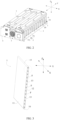
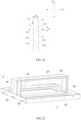
- a battery pack of the present application includes a temperature control component 1, multiple batteries 2, a lower box 3, an air duct component 4, a fan 5, a cable tie 6, an upper box cover 7, an end plate 8, an installation panel 9 and a harness isolation plate 10.
- the multiple batteries 2 include a first battery 2A and a second battery 2B, and the temperature control component 1 is disposed between the first battery 2A and the second battery 2B.
- both the first battery 2A and the second battery 2B may be multiple in number, the multiple first batteries 2A and the multiple second batteries 2B can be alternately arranged in a longitudinal direction Y, and the temperature control component 1 can be disposed between each first battery 2A and each second battery 2B which are adjacent.
- the temperature control component 1 can be made of a metal material, such as an aluminum profile.
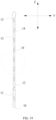
- the temperature control component 1 may include a first side plate 11, a second side plate 12, a first buffer plate 13, a first connection plate 15 and a second connection plate 16.
- the first side plate 11, the second side plate 12, the first buffer plate 13, the first connection plate 15 and the second connection plate 16 can be integrally formed with an aluminum extrusion process.
- the first side plate 11 is disposed opposite to the second side plate 12 in the longitudinal direction Y, and the second side plate 12 is connected with the first side plate 11 via the first connection plate 15 and the second connection plate 16.
- the first side plate 11 and the second side plate 12 are disposed directly facing large surfaces of corresponding batteries 2, and when external air flows through the temperature control component 1, heat dissipation treatment of the batteries 2 can be realized.
- the first connection plate 15 connects one end of the first side plate 11 and one end of the second side plate 12, and the second connection plate 16 connects the other end of the first side plate 11 and the other end of the second side plate 12, so that the first side plate 11, the second side plate 12, the first connection plate 15 and the second connection plate 16 together form a surrounding frame structure with a cavity.
- the first buffer plate 13 is disposed between the second side plate 12 and the first side plate 11 and is connected with the second side plate 12 and the first side plate 11 to divide the cavity into multiple channels F, and at least part of the first buffer plate 13 extends obliquely from the first side plate 11 towards the second side plate 12.
- the first buffer plate 13 may be multiple in number, and the first buffer plates 13 are spaced apart in an up-down direction Z to divide the cavity into multiple channels F.
- the batteries 2 will generate expansion forces.
- expansion forces of two adjacent batteries 2 that is, the first battery 2A and the second battery 2B
- the first side plate 11 and the second side plate 12 transmit the expansion forces to the first buffer plate 13. Since at least part of the first buffer plate 13 extends obliquely from the first side plate 11 towards the second side plate 12, the expansion forces transmitted to the first buffer plate 13 via the first side plate 11 and the second side plate 12 are greatly reduced, thereby extending the service life of the temperature control component 1.
- the at least part of the first buffer plate 13 which extends obliquely is more prone to a bending deformation under the action of the expansion forces, so that the temperature control component 1 could absorb the expansion forces of the batteries 2 in time, thereby greatly improving the service life of the batteries 2.
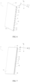
- the size of an angle formed by an extension direction of the first buffer plate 13 (that is, a direction in which the at least part of the first buffer plate 13 extends) and the first side plate 11 and the size of an angle formed by the extension direction of the first buffer plate 13 and the second side plate 12 determine the amplitude of the expansion forces transmitted to the first buffer plate 13 via the first side plate 11 and the second side plate 12. If the expansion forces applied to the first buffer plate 13 are too large, the first buffer plate 13 will be broken. Therefore, in order to prevent the first buffer plate 13 from being broken by excessive expansion forces, preferably, with reference to FIG. 8 , FIG. 15 and FIG.
- an acute angle ⁇ 1 formed by the extension direction of the first buffer plate 13 and the first side plate 11 is not more than 45° (an acute angle formed by the first buffer plate 13 and the second side plate 12 is equal to the acute angle formed by the first buffer plate 13 and the first side plate 11).
- the first buffer plate 13 is disposed between the first side plate 11 and the second side plate 12 of the temperature control component 1, and the first buffer plate 13 is formed by extending, in entirety, obliquely from the first side plate 11 towards the second side plate 12.
- the first buffer plate 13 can be formed by extending, in entirety, in an oblique upward direction from the first side plate 11 towards the second side plate 12, or the first buffer plate 13 can be formed by extending, in entirety, in an oblique downward direction from the first side plate 11 towards the second side plate 12.
- the first buffer plate 13 may be formed into a flat plate structure or an arc-shaped plate structure.
- the first buffer plate 13 may be formed into a structure which has a uniform thickness; or, the first buffer plate 13 may be formed into a structure which is thick in the middle and thin at both ends; or, the first buffer plate 13 may be formed into a structure which is thin in the middle and thick at both ends.
- the first buffer plate 13 is disposed between the first side plate 11 and the second side plate 12 of the temperature control component 1, and at this time, the first buffer plate 13 can be formed into a wave-shaped structure (also known as a corrugated plate structure).
- the first buffer plate 13 is formed by alternately extending in an oblique upward direction from the first side plate 11 towards the second side plate 12 and an oblique downward direction from the first side plate 11 towards the second side plate 12.
- the first buffer plate 13 of this structure is formed with protrusions, and each protrusion is formed into an arc-shaped structure. Based on the shape structure of each protrusion, the first buffer plate 13 has sufficient space for a bending deformation, so that the temperature control component 1 could absorb the expansion forces of the batteries 2 in time, which greatly improves the service life of the batteries 2.
- the first buffer plate 13 is formed by extending, in entirety, obliquely upward from the first side plate 11 towards the second side plate 12, and the temperature control component 1 also includes a second buffer plate 14.
- the second buffer plate 14 is disposed between the second side plate 12 and the first side plate 11 and is connected with the second side plate 12 and the first side plate 11, and the second buffer plate 14 is formed by extending obliquely downward from the first side plate 11 towards the second side plate 12.
- the second buffer plate 14 is used to absorb the expansion forces of the batteries 2 together with the first buffer plate 13, thereby greatly improving the service life of the batteries 2.
- the second buffer plate 14 may be multiple in number, and the multiple second buffer plates 14 are spaced apart in the up-down direction Z to divide the cavity into multiple channels F together with the first buffer plate 13.
- the size of an angle formed by an extension direction of the second buffer plate 14 and the first side plate 11 and the size of an angle formed by the extension direction of the second buffer plate 14 and the second side plate 12 determine the amplitude of expansion forces transmitted to the second buffer plate 14 via the first side plate 11 and the second side plate 12. If the expansion forces applied to the second buffer plate 14 are too large, the second buffer plate 14 will be broken. Therefore, in order to prevent the second buffer plate 14 from being broken by excessive expansion forces, preferably, with reference to FIG. 8 , FIG. 20 and FIG.
- an acute angle ⁇ 2 formed by the extension direction of the second buffer plate 14 and the first side plate 11 is not more than 45° (an acute angle formed by the second buffer plate 14 and the second side plate 12 is equal to the acute angle formed by the second buffer plate 14 and the first side plate 11).
- the second buffer plate 14 is spaced apart from the first buffer plate 13 in the up-down direction Z, and the first buffer plate 13 and the second buffer plate 14 are arranged in a staggered manner. At this time, the first buffer plate 13 and the second buffer plate 14 are formed into a " "-shaped structure.
- the " "-shaped structure ensures structural stability of the temperature control component 1 and improves structural strength of the temperature control component 1.
- the second buffer plate 14 is directly connected with the first buffer plate 13; and the first buffer plate 13, the second buffer plate 14 and a corresponding part of the first side plate 11 form a triangular structure, and the first buffer plate 13, the second buffer plate 14 and a corresponding part of the second side plate 12 also form a triangular structure.
- Such triangular structure ensures the structural stability of the temperature control component 1 and improves the structural strength of the temperature control component 1.
- the second buffer plate 14 is directly connected with the first buffer plate 13, and the first buffer plate 13 and the second buffer plate 14 are formed into an arch structure.
- Such arch structure ensures the structural stability of the temperature control component 1 and improves the structural strength of the temperature control component 1.
- the first buffer plate 13 and the second buffer plate 14 may be formed into a structure which has a uniform thickness (as shown in FIG. 6 and FIG. 7 ). Or, the first buffer plate 13 and the second buffer plate 14 may be formed into a structure which is thick in the middle and thin at both ends. Or, the first buffer plate 13 and the second buffer plate 14 may be formed into a structure which is thin in the middle and thick at both ends (as shown in FIG. 5 and FIG. 8 ). The first buffer plate 13 and the second buffer plate 14 may be formed into a flat plate structure (as shown in FIG. 6 ) or an arc-shaped plate structure (as shown in FIG. 7 ).
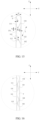
- the first side plate 11 may be provided with: a first limit protrusion 111, extending towards the second side plate 12 in the longitudinal direction Y and located within a corresponding channel F, and the first limit protrusion 111 is situated within a projection area of the first buffer plate 13 on the first side plate 11.
- the second side plate 12 may be provided with: a second limit protrusion 121, extending towards the first side plate 11 in the longitudinal direction Y and located within a corresponding channel F, and the second limit protrusion 121 is situated within a projection area of the first buffer plate 13 on the second side plate 12.
- the first buffer plate 13 will finally lean against the first limit protrusion 111 and the second limit protrusion 121 (as shown in FIG. 16 and FIG. 21 ).
- the bending deformation of the first buffer plate 13 is restricted, and the corresponding channel F still has a ventilation space to meet thermal management requirements, thus improving thermal management performance of the temperature control component 1 to the batteries 2, and greatly improving the service life of the batteries 2.
- the first limit protrusion 111 is disposed opposite to the second limit protrusion 121. Specifically, the first limit protrusion 111 is flush with the second limit protrusion 121 in the longitudinal direction Y; or, the first limit protrusion 111 and the second limit protrusion 121 are staggered in the up-down direction Z.
- the number of the first limit protrusion 111 and the number of the second limit protrusion 121 can be selectively set according to strength requirements.
- the first limit protrusion 111 of the first side plate 11 may be one in number.
- the first limit protrusion 111 may be multiple in number.
- the second limit protrusion 121 may also be one (as shown in FIG. 18 to FIG. 22 ) or multiple (as shown in FIG. 12 to FIG. 17 ) in number.
- the first buffer plate 13 has a length of L and has a first end 131 and a second end 132; the first end 131 is connected with the first side plate 11, and the second end 132 is connected with the second side plate 12.
- a distance between the first limit protrusion 111 and the first end 131 in the up-down direction Z is a 1 (that is, a distance between an edge of the first end 131 close to the first limit protrusion 111 and an edge of the first limit protrusion 111 close to the first end 131), and 0 ⁇ a 1 ⁇ L / 2.
- the first limit protrusion 111 is multiple in number (as shown in FIG. 20 ).
- a distance between the multiple first limit protrusions 111 and the first end 131 in the up-down direction Z is a 2 (that is, a distance between an edge of the first end 131 close to the first limit protrusions 111 and an edge of one of the first limit protrusions 111 closest to the first end 131), and 0 ⁇ a 2 ⁇ L / 2.
- the size of the parameter a 1 determines a disposed position of the first limit protrusion 111 on the first side plate 11.
- the first limit protrusion 111 needs to be disposed between a position at which a maximum free deformation arc of the first buffer plate 13 is tangent to the first side plate 11 and the first end 131, that is 0 ⁇ a 1 ⁇ L / 2 (or 0 ⁇ a 2 ⁇ L / 2 ).
- the first limit protrusion 111 has difficulty in or even is incapable of performing a limiting effect to the bending deformation of the first buffer plate 13.
- a distance between the second limit protrusion 121 and the second end 132 in the up-down direction Z is b 1 (that is, a distance between an edge of the second end 132 close to the second limit protrusion 121 and an edge of the second limit protrusion 121 close to the second end 132), and 0 ⁇ b 1 ⁇ L / 2.
- the second limit protrusions 121 is multiple in number (as shown in FIG. 22 ).
- a distance between the multiple second limit protrusions 121 and the second end 132 in the up-down direction Z is b 2 (that is, a distance between an edge of the second end 132 close to the second limit protrusions 121 and an edge of one of the second limit protrusions 121 closest to the second end 132), and 0 ⁇ b 2 ⁇ L / 2.
- the size of the parameter b 1 determines a disposed position of the second limit protrusion 121 on the second side plate 12.
- the second limit protrusion 121 needs to be disposed between a position at which a maximum free deformation arc of the first buffer plate 13 is tangent to the second side plate 12 and the second end 132, that is 0 ⁇ b 1 ⁇ L / 2 (or 0 ⁇ b 2 ⁇ L / 2) .
- the second limit protrusion 121 has difficulty in or even is incapable of performing a limiting effect to the bending deformation of the first buffer plate 13.
- the temperature control component 1 has a thickness of H in the longitudinal direction Y
- the first limit protrusion 111 has a height of h 1 in the longitudinal direction Y, and 0 ⁇ h 1 ⁇ H / 2
- the second limit protrusion 121 has a height of h 2 in the longitudinal direction Y, and 0 ⁇ h 2 ⁇ H / 2. This is because, if h 1 > H / 2 (or h 2 > H / 2), the first buffer plate 13 generates a very small degree of bending deformation during expansion deformations of the batteries 2, which cannot absorb the expansion deformations of the batteries 2 in time, so that the temperature control component 1 cannot meet expansion force requirements of the batteries 2.
- the first limit protrusion 111 when the first limit protrusion 111 is one in number, H / 8 ⁇ h 1 ⁇ H / 2; and when the first limit protrusion 111 is multiple in number, the multiple first limit protrusions 111 have the same height, and H / 20 ⁇ h 1 ⁇ H / 8 .
- first limit protrusion 111 when there is only one first limit protrusion 111, a contact between the first buffer plate 13 subjected to the bending deformation and the first limit protrusion 111 is equivalent to a point contact. At this time, the degree of the bending deformation of the first buffer plate 13 is relatively small. If the first limit protrusion 111 intends to play a position limiting effect on the first buffer plate 13, its height h 1 in the longitudinal direction Y cannot be too small, that is H / 8 ⁇ h 1 ⁇ H / 2. When the first limit protrusion 111 is multiple in number, a contact between the first buffer plate 13 subjected to the bending deformation and the multiple first limit protrusions 111 is equivalent to a plane contact.
- the degree of the bending deformation of the first buffer plate 13 is relatively large, and the height h 1 of the multiple first limit protrusions 111 in the longitudinal direction Y can be appropriately reduced, that is H / 20 ⁇ h 1 ⁇ H / 8 .
- the first limit protrusion 111 and the second limit protrusion 121 can be disposed in an embodiment with only the first buffer plate 13, for example, the above-mentioned first embodiment.
- the first limit protrusion 111 and the second limit protrusion 121 may also be disposed in an embodiment with both the first buffer plate 13 and the second buffer plate 14, for example, the above-mentioned third embodiment, where the second buffer plate 14 can be formed into a plate-shaped structure or an arc-shaped structure, and the second buffer plate 14 is used to absorb the expansion deformations of the batteries 2 together with the first buffer plate 13, thereby ensuring that the temperature control component 1 meets expansion force requirements of the batteries 2, and improving the service life of the batteries 2.
- the second buffer plate 14 can be spaced apart from the first buffer plate 13 in the up-down direction Z. At this time, the second buffer plate 14, the first buffer plate 13, the first side plate 11 and the second side plate 12 enclose a trapezoid channel F.
- the second buffer plate 14 can be directly connected with the first buffer plate 13. At this time, the second buffer plate 14, the first buffer plate 13 and the first side plate 11 enclose a triangular channel F, and the second buffer plate 14, the first buffer plate 13 and the second side plate 12 also enclose a triangular channel F.
- the second buffer plate 14 will finally lean against the third limit protrusion 112 and the fourth limit protrusion 122 (as shown in FIG. 16 and FIG. 21 ).
- the bending deformation of the second buffer plate 14 is restricted, and the corresponding channel F still has a ventilation space to meet thermal management requirements, thus improving the thermal management performance of the temperature control component 1 to the batteries 2, and greatly improving the service life of the batteries 2.
- the second buffer plate 14 has a third end 141 and a fourth end 142; the third end 141 is connected with the first side plate 11, and the fourth end 142 is connected with the second side plate 12.
- a positional relationship between the third limit protrusion 112 and the third end 141 is consistent with a positional relationship between the first limit protrusion 111 and the first end 131, and a positional relationship between the fourth limit protrusion 122 and the fourth end 142 is consistent with a positional relationship between the second limit protrusion 121 and the second end 132, which will not be described in detail here.
- the third limit protrusion 112 is disposed opposite to the fourth limit protrusion 122. Specifically, the third limit protrusion 112 is flush with the fourth limit protrusion 122 in the longitudinal direction Y; or, the third limit protrusion 112 and the fourth limit protrusion 122 are staggered in the up-down direction Z.
- the number of the third limit protrusion 112 and the number of the fourth limit protrusion 122 can be selectively set according to strength requirements.
- the first side plate 11, the second side plate 12, the first buffer plate 13, the second buffer plate 14, the first connection plate 15 and the second connection plate 16 can be integrally formed with an aluminum extrusion process.
- Both the first buffer plate 13 and the second buffer plate 14 can be multiple in number, and the second buffer plate 14 and the first buffer plate 13 can be arranged in a staggered order.
- each second buffer plate 14 and each first buffer plate 13 which are adjacent in the up-down direction Z enclose a channel F respectively with a corresponding portion of the first side plate 11 and a corresponding portion of the second side plate 12.
- the cavity formed by the first side plate 11, the second side plate 12, the first connection plate 15 and the second connection plate 16 together is divided into multiple channels F by the first buffer plate 13 and the second buffer plate 14.
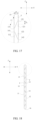
- the channel F may have: a wide surface F1, a narrow surface F2 and a position-limiting protrusion F3; the narrow face F2 is disposed opposite to the wide surface F1 in the longitudinal direction Y, the position-limiting protrusion F3 protrudes from the wide surface F1 in the longitudinal direction Y and is spaced apart from the narrow surface F2, and at least part of the position-limiting protrusion F3 is situated within a projection area of the narrow surface F2 on the wide surface F1.
- the position-limiting protrusion F3 within the channel F can be one or multiple in number.
- the batteries 2 will generate expansion forces, and expansion forces of two adjacent batteries 2 (that is, the first battery 2A and the second battery 2B) will extrude the first side plate 11 and the second side plate 12 respectively, while the first side plate 11 and the second side plate 12 will transmit the expansion forces to the first buffer plate 13 and the second buffer plate 14. Due to the oblique arrangement of the first buffer plate 13 and the second buffer plate 14, the first buffer plate 13 and the second buffer plate 14 are prone to bending deformations under the action of the expansion forces so as to absorb the expansion forces of the batteries 2 in time, thereby ensuring that the temperature control component 1 meets expansion force requirements of the batteries 2.
- the first buffer plate 13 is located below the second buffer plate 14; the wide surface F1 of the channel F is a surface of the first side plate 11 facing the second side plate 12, and the narrow surface F2 is a surface of the second side plate 12 facing the first side plate 11, that is, the position-limiting protrusion F3 within the channel F is disposed on the first side plate 11.
- the first buffer plate 13 may have: a first end 131 connected with the first side plate 11; and a second end 132 connected with the second side plate 12.
- the second buffer plate 14 may have: a third end 141 connected with the first side plate 11; and a fourth end 142 connected with the second side plate 12.
- the wide surface F1 of the channel F is a portion of surface of the first side plate 11 between the first end 131 and the third end 141
- the narrow surface F2 is a portion of surface of the second side plate 12 between the second end 132 and the fourth end 142.
- the first side plate 11 has a wall thickness of c 1 in the longitudinal direction Y, and a surface of the position-limiting protrusion F3 facing the narrow surface F2 has a size of b in the up-down direction Z, as shown in FIG. 30 .
- a surface of the position-limiting protrusion F3 facing the narrow surface F2 has a size of b in the up-down direction Z, as shown in FIG. 30 .
- the first buffer plate 13 is located above the second buffer plate 14; the wide surface F1 of the channel F is a surface of the second side plate 12 facing the first side plate 11, and the narrow surface F2 is a surface of the first side plate 11 facing the second side plate 12, that is, the position-limiting protrusion F3 within the channel F is disposed on the second side plate 12.
- the second side plate 12 has a wall thickness of c 2 in the longitudinal direction Y, and a surface of the position-limiting protrusion F3 facing the narrow surface F2 has a size of b in the up-down direction Z, as shown in FIG. 30 .
- the temperature control component 1 has a thickness of H in the longitudinal direction Y
- the position-limiting protrusion F3 has a height of a in the longitudinal direction Y.
- the height a of the position-limiting protrusion F3 determines the size of the ventilation space of the channel F subjected to deformation, in order to ensure the thermal management performance of the temperature control component 1 on the batteries 2, 1 / 5H ⁇ a ⁇ H.
- the position-limiting protrusion F3 may have: a main body part F31, extending from the wide surface F1 towards the narrow surface F2; and a protrusion part F32, disposed at an end of the main body part F31 close to the narrow surface F2 and protrudes from the main body part F31 in a circumferential direction (that is, the size of the protrusion part F32 in the circumferential direction is larger than the size of the main body part F31 in the circumferential direction), and at least part of the protrusion part F32 is situated within a projection area of the narrow surface F2 on the wide surface F1.
- the protrusion part F32 of the position-limiting protrusion F3 will extrude a large surface of a corresponding battery 2 through the narrow surface F2. Because the size of the protrusion part F32 in the circumferential direction is larger than the size of the main body part F31 in the circumferential direction, the ventilation space of the channel F subjected to deformation is not reduced as much as possible, and a contact area between the protrusion part F32 and the narrow surface F2 is also guaranteed to reduce the extrusion pressure of the position-limiting protrusion F3 on the corresponding battery 2.
- the lower box 3 is used to support the multiple batteries 2.
- the multiple batteries 2 can be arranged in at least two rows of battery banks S in a lateral direction X, and the air duct component 4 is disposed between the two rows of battery banks S and fixed to the lower box 3.
- the temperature control component 1 has multiple channels F; an air duct is formed between the air duct component 4 and a corresponding battery bank S, and the air duct is in communication with multiple channels F of a corresponding temperature control component 1 and a fan 5.
- the air duct component 4 may include an air volume regulating plate 41, a first support plate 42, a second support plate 43, a mounting plate 44, and a sealing strip 45.
- the air volume regulating plate 41 is disposed within the air duct; the first support plate 42 is spaced apart from the second support plate 43 in the longitudinal direction Y, and the first support plate 42 is close to the fan 5.
- the height of the air volume regulating plate 41 decreases sequentially in a direction from the first support plate 42 towards the second support plate 43, so that the air duct expands from a side close to the fan 5 to a side away from the fan 5 in the longitudinal direction Y.
- the mounting plate 44 extends in the longitudinal direction Y and is connected with the first support plate 42 and the second support plate 43, and the air volume regulating plate 41 is fixedly mounted on the mounting plate 44.
- the sealing strip 45 is disposed on the first support plate 42, the second support plate 43 and the mounting plate 44. When the air duct component 4 is assembled with multiple batteries 2, the sealing strip 45 is adhered to a corresponding battery bank S for a sealing connection with the battery bank S.
- the end plate 8 is disposed at both ends of each battery bank S in the longitudinal direction Y.
- the cable tie 6 tightly bundles, in the circumferential direction, all the batteries 2 in a corresponding battery bank S, a corresponding temperature control component 1 and two corresponding end plates 8.
- the installation panel 9 is located on an outer side of a corresponding end plate 8 in the longitudinal direction Y; is fixedly connected with the lower box 3 and the corresponding end plate 8; and is fixedly installed with the fan 5.
- Embodiment 1 A temperature control component, characterized by comprising:
- Embodiment 2 The temperature control component according to embodiment 1, characterized in that the first buffer plate (13) is formed into a wave-shaped structure.
- Embodiment 3 The temperature control component according to embodiment 1 or 2, characterized in that the first buffer plate (13) is formed by extending, in entirety, obliquely from the first side plate (11) towards the second side plate (12).
- Embodiment 4 The temperature control component according to embodiment 1 or 3, characterized in that the first buffer plate (13) is formed into a flat plate structure or an arc-shaped plate structure.
- Embodiment 5 The temperature control component according to any one of embodiments 1-4, characterized in that,
- Embodiment 6 The temperature control component according to embodiment 5, characterized in that,
- Embodiment 7 The temperature control component according to any one of embodiments 1-6, characterized by comprising:
- Embodiment 8 The temperature control component (1) according to any one of embodiments 1-7, characterized in that an acute angle ⁇ 1 formed by an extension direction of the first buffer plate (13) and the first side plate (11) is not more than 45°.
- Embodiment 9 The temperature control component (1) according to embodiment 7 or 8, characterized in that,
- Embodiment 10 The temperature control component (1) according to any one of embodiments 7-9, characterized in that,
- Embodiment 11 The temperature control component (1) according to any one of embodiments 7-10, characterized in that,
- Embodiment 12 The temperature control component (1) according to embodiment 11, characterized in that,
- Embodiment 14 The temperature control component (1) according to any one of embodiments 7-13, characterized in that,
- Embodiment 15 The temperature control component according to embodiment 5, 6 or 14, characterized in that the second buffer plate (14) is spaced apart from the first buffer plate (13) in an up-down direction (Z).
- Embodiment 16 The temperature control component according to embodiment 5, 6, 14 or 15, characterized in that the second buffer plate (14) is directly connected with the first buffer plate (13).
- Embodiment 17 The temperature control component according to embodiment 15 or 16, characterized in that,
- Embodiment 18 The temperature control component (1) according to embodiment 17, characterized in that the first buffer plate (13) is located below the second buffer plate (14), and the wide surface (F1) of the channel (F) is a surface of the first side plate (11) facing the second side plate (12).
- Embodiment 19 The temperature control component (1) according to embodiment 17 or 18, characterized in that,
- Embodiment 20 The temperature control component (1) according to embodiment 19, characterized in that the narrow surface (F2) has a size of l in the up-down direction (Z), and 2.5 c 1 ⁇ b ⁇ l.
- Embodiment 24 The temperature control component (1) according to any one of embodiments 17-23, characterized in that,
- Embodiment 26 The temperature control component (1) according to any one of embodiments 17-25, characterized in that,
Landscapes
- Chemical & Material Sciences (AREA)
- Chemical Kinetics & Catalysis (AREA)
- Electrochemistry (AREA)
- General Chemical & Material Sciences (AREA)
- Engineering & Computer Science (AREA)
- Manufacturing & Machinery (AREA)
- Secondary Cells (AREA)
- Battery Mounting, Suspending (AREA)
- Physics & Mathematics (AREA)
- Algebra (AREA)
- General Physics & Mathematics (AREA)
- Mathematical Analysis (AREA)
- Mathematical Optimization (AREA)
- Pure & Applied Mathematics (AREA)
Applications Claiming Priority (5)
| Application Number | Priority Date | Filing Date | Title |
|---|---|---|---|
| CN201910528260.9A CN112103418B (zh) | 2019-06-18 | 2019-06-18 | 温控组件及电池包 |
| CN201910528787.1A CN112103419B (zh) | 2019-06-18 | 2019-06-18 | 温控组件及电池包 |
| CN201910528792.2A CN112103420B (zh) | 2019-06-18 | 2019-06-18 | 温控组件及电池包 |
| PCT/CN2020/096395 WO2020253684A1 (fr) | 2019-06-18 | 2020-06-16 | Ensemble de régulation de température et bloc-batterie |
| EP20775799.8A EP3780147A4 (fr) | 2019-06-18 | 2020-06-16 | Ensemble de régulation de température et bloc-batterie |
Related Parent Applications (1)
| Application Number | Title | Priority Date | Filing Date |
|---|---|---|---|
| EP20775799.8A Division EP3780147A4 (fr) | 2019-06-18 | 2020-06-16 | Ensemble de régulation de température et bloc-batterie |
Publications (1)
| Publication Number | Publication Date |
|---|---|
| EP4550539A2 true EP4550539A2 (fr) | 2025-05-07 |
Family
ID=74037584
Family Applications (2)
| Application Number | Title | Priority Date | Filing Date |
|---|---|---|---|
| EP20775799.8A Pending EP3780147A4 (fr) | 2019-06-18 | 2020-06-16 | Ensemble de régulation de température et bloc-batterie |
| EP24213130.8A Pending EP4550539A2 (fr) | 2019-06-18 | 2020-06-16 | Ensemble de régulation de température et bloc-batterie |
Family Applications Before (1)
| Application Number | Title | Priority Date | Filing Date |
|---|---|---|---|
| EP20775799.8A Pending EP3780147A4 (fr) | 2019-06-18 | 2020-06-16 | Ensemble de régulation de température et bloc-batterie |
Country Status (5)
| Country | Link |
|---|---|
| US (1) | US11936026B2 (fr) |
| EP (2) | EP3780147A4 (fr) |
| JP (2) | JP7307193B2 (fr) |
| KR (1) | KR102622749B1 (fr) |
| WO (1) | WO2020253684A1 (fr) |
Families Citing this family (22)
| Publication number | Priority date | Publication date | Assignee | Title |
|---|---|---|---|---|
| WO2023123039A1 (fr) * | 2021-12-29 | 2023-07-06 | 宁德时代新能源科技股份有限公司 | Batterie, son procédé de fabrication, son dispositif de fabrication et appareil électrique |
| CN121460830A (zh) * | 2022-02-21 | 2026-02-03 | 宁德时代新能源科技股份有限公司 | 电池和用电装置 |
| EP4254605A4 (fr) * | 2022-02-21 | 2023-10-04 | Contemporary Amperex Technology Co., Limited | Batterie, dispositif électrique et procédé et dispositif de préparation de batterie |
| CN116868417B (zh) * | 2022-02-21 | 2024-07-16 | 宁德时代新能源科技股份有限公司 | 电池和用电装置 |
| WO2024031413A1 (fr) * | 2022-08-10 | 2024-02-15 | 宁德时代新能源科技股份有限公司 | Batterie et dispositif électrique |
| KR102937048B1 (ko) * | 2022-02-21 | 2026-03-09 | 컨템포러리 엠퍼렉스 테크놀로지 (홍콩) 리미티드 | 배터리, 전기 장치, 배터리 제조 방법 및 장치 |
| CN217788555U (zh) * | 2022-04-29 | 2022-11-11 | 宁德时代新能源科技股份有限公司 | 热管理部件、电池及用电装置 |
| CN114824615B (zh) * | 2022-05-06 | 2023-02-21 | 池州市安安新材科技有限公司 | 一种高强度轻量化新能源汽车电池包壳体 |
| CN218586079U (zh) * | 2022-05-26 | 2023-03-07 | 宁德时代新能源科技股份有限公司 | 热管理部件、电池以及用电装置 |
| WO2023230899A1 (fr) * | 2022-05-31 | 2023-12-07 | 浙江极氪智能科技有限公司 | Plaque de refroidissement liquide, bloc-batterie et automobile |
| CN218334077U (zh) * | 2022-09-05 | 2023-01-17 | 宁德时代新能源科技股份有限公司 | 冷却结构、电池及用电装置 |
| DE102022123454A1 (de) | 2022-09-14 | 2024-03-14 | Dr. Ing. H.C. F. Porsche Aktiengesellschaft | Kraftfahrzeug-Traktionsbatteriemodul |
| DE102022126590A1 (de) * | 2022-10-12 | 2024-04-18 | Parker Hannifin EMEA S.à.r.l | Einlageelement für ein Batteriemodul sowie Batteriemodul |
| CN116848704B (zh) * | 2022-11-23 | 2024-08-09 | 宁德时代新能源科技股份有限公司 | 换热组件、电池及用电装置 |
| WO2024145778A1 (fr) * | 2023-01-03 | 2024-07-11 | 宁德时代新能源科技股份有限公司 | Composant de gestion thermique, batterie et dispositif électrique |
| CN219017773U (zh) * | 2023-01-28 | 2023-05-12 | 宁德时代新能源科技股份有限公司 | 换热部件、箱体、电池及用电装置 |
| CN219350392U (zh) * | 2023-03-23 | 2023-07-14 | 欣旺达电动汽车电池有限公司 | 电池包及用电装置 |
| CN116505121A (zh) * | 2023-04-04 | 2023-07-28 | 北京双登慧峰聚能科技有限公司 | 一种风冷电池模块 |
| EP4611122A4 (fr) * | 2023-09-12 | 2026-04-08 | Eve Energy Co Ltd | Dispositif de refroidissement de liquide, ensemble de communication et bloc-batterie |
| KR20250065224A (ko) | 2023-11-03 | 2025-05-12 | 주식회사 엘지에너지솔루션 | 배터리 조립체 및 이를 포함하는 배터리 팩 |
| CN120239925A (zh) * | 2023-11-24 | 2025-07-01 | 厦门新能达科技有限公司 | 电池模组、电池包以及用电设备 |
| DE102024121406A1 (de) * | 2024-07-26 | 2026-01-29 | Audi Aktiengesellschaft | Batteriemodul und Zelltrennelement mit Kühlfunktion |
Family Cites Families (25)
| Publication number | Priority date | Publication date | Assignee | Title |
|---|---|---|---|---|
| JP2000048867A (ja) * | 1998-07-31 | 2000-02-18 | Toyota Motor Corp | 組電池 |
| JP4813707B2 (ja) * | 2001-09-28 | 2011-11-09 | 本田技研工業株式会社 | 燃料電池スタック |
| JP4242665B2 (ja) * | 2002-05-13 | 2009-03-25 | パナソニック株式会社 | 組電池の冷却装置及び二次電池 |
| JP4096358B2 (ja) | 2003-01-31 | 2008-06-04 | 株式会社ジーエス・ユアサコーポレーション | 電池 |
| JP2006073461A (ja) | 2004-09-06 | 2006-03-16 | Toyota Motor Corp | 組電池 |
| KR100612239B1 (ko) * | 2005-04-26 | 2006-08-11 | 삼성에스디아이 주식회사 | 이차 전지 모듈과 이차 전지 모듈을 이루는 이차 전지의격벽 |
| KR100841670B1 (ko) * | 2006-10-10 | 2008-06-26 | 현대에너셀 주식회사 | 방열판을 가지는 전지모듈 |
| JP2008201371A (ja) * | 2007-02-22 | 2008-09-04 | Toyota Motor Corp | ダクト構造 |
| JP5518384B2 (ja) | 2009-07-14 | 2014-06-11 | 三洋電機株式会社 | 組電池及びこれを備える車両 |
| US9780421B2 (en) * | 2010-02-02 | 2017-10-03 | Dana Canada Corporation | Conformal heat exchanger for battery cell stack |
| DE102010007633A1 (de) * | 2010-02-05 | 2011-08-11 | Dr. Ing. h.c. F. Porsche Aktiengesellschaft, 70435 | Fahrzeug mit elektrischer Antriebsvorrichtung |
| JP5796879B2 (ja) * | 2010-09-06 | 2015-10-21 | 日産自動車株式会社 | 燃料電池スタック及び燃料電池スタックに用いる変形吸収部材 |
| WO2012173269A1 (fr) * | 2011-06-17 | 2012-12-20 | 株式会社リチウムエナジージャパン | Bloc de batteries |
| WO2013095476A1 (fr) | 2011-12-21 | 2013-06-27 | Mission Motors | Module de batterie |
| US20150037662A1 (en) * | 2013-07-30 | 2015-02-05 | Johnson Controls Technology Company | System and method for sealing a battery cell |
| JP5942943B2 (ja) * | 2013-08-20 | 2016-06-29 | トヨタ自動車株式会社 | 電池温度調節装置 |
| JP6241176B2 (ja) * | 2013-09-27 | 2017-12-06 | 株式会社Gsユアサ | 電源モジュール及び緩衝具 |
| JP6159658B2 (ja) * | 2013-12-18 | 2017-07-05 | 古河電池株式会社 | 中仕切り板 |
| KR101816974B1 (ko) | 2014-11-17 | 2018-02-21 | 주식회사 엘지화학 | 이차전지용 냉각 플레이트 및 이를 포함하는 이차전지 모듈 |
| JP6571577B2 (ja) * | 2016-03-30 | 2019-09-04 | トヨタ自動車株式会社 | 組電池 |
| KR102155330B1 (ko) * | 2016-11-29 | 2020-09-11 | 주식회사 엘지화학 | 공냉식 배터리 모듈 |
| JP2019046578A (ja) | 2017-08-30 | 2019-03-22 | 日産自動車株式会社 | バッテリパックの製造方法 |
| CN210136908U (zh) * | 2019-06-18 | 2020-03-10 | 宁德时代新能源科技股份有限公司 | 温控组件及电池包 |
| CN210136907U (zh) * | 2019-06-18 | 2020-03-10 | 宁德时代新能源科技股份有限公司 | 温控组件及电池包 |
| CN210136906U (zh) * | 2019-06-18 | 2020-03-10 | 宁德时代新能源科技股份有限公司 | 温控组件及电池包 |
-
2020
- 2020-06-16 JP JP2021558705A patent/JP7307193B2/ja active Active
- 2020-06-16 WO PCT/CN2020/096395 patent/WO2020253684A1/fr not_active Ceased
- 2020-06-16 US US17/044,473 patent/US11936026B2/en active Active
- 2020-06-16 KR KR1020217035608A patent/KR102622749B1/ko active Active
- 2020-06-16 EP EP20775799.8A patent/EP3780147A4/fr active Pending
- 2020-06-16 EP EP24213130.8A patent/EP4550539A2/fr active Pending
-
2023
- 2023-06-27 JP JP2023104619A patent/JP7748422B2/ja active Active
Also Published As
| Publication number | Publication date |
|---|---|
| EP3780147A4 (fr) | 2021-10-13 |
| KR20210139466A (ko) | 2021-11-22 |
| JP2023123690A (ja) | 2023-09-05 |
| KR102622749B1 (ko) | 2024-01-08 |
| EP3780147A1 (fr) | 2021-02-17 |
| JP7307193B2 (ja) | 2023-07-11 |
| JP7748422B2 (ja) | 2025-10-02 |
| US11936026B2 (en) | 2024-03-19 |
| US20230091830A1 (en) | 2023-03-23 |
| JP2022536884A (ja) | 2022-08-22 |
| WO2020253684A1 (fr) | 2020-12-24 |
Similar Documents
| Publication | Publication Date | Title |
|---|---|---|
| EP4550539A2 (fr) | Ensemble de régulation de température et bloc-batterie | |
| US12206083B2 (en) | Temperature control component and battery pack | |
| CN210136907U (zh) | 温控组件及电池包 | |
| KR102755692B1 (ko) | 온도 조절 어셈블리 및 배터리 팩 | |
| JP2022536884A5 (fr) | ||
| CN210136906U (zh) | 温控组件及电池包 | |
| CN112103418B (zh) | 温控组件及电池包 | |
| CN112103419B (zh) | 温控组件及电池包 | |
| CN211376748U (zh) | 温控组件及电池包 | |
| CN112103420A (zh) | 温控组件及电池包 | |
| CN210136908U (zh) | 温控组件及电池包 | |
| CN212230472U (zh) | 动力电池包及具有其的车辆 | |
| CN118970338B (zh) | 电池箱体 | |
| CN220233301U (zh) | 一种电池模组 | |
| US20260047037A1 (en) | Liquid cooling plate | |
| CN113809427A (zh) | 散热结构和具有其的电池包组件、车辆 |
Legal Events
| Date | Code | Title | Description |
|---|---|---|---|
| PUAI | Public reference made under article 153(3) epc to a published international application that has entered the european phase |
Free format text: ORIGINAL CODE: 0009012 |
|
| STAA | Information on the status of an ep patent application or granted ep patent |
Free format text: STATUS: REQUEST FOR EXAMINATION WAS MADE |
|
| 17P | Request for examination filed |
Effective date: 20241114 |
|
| AC | Divisional application: reference to earlier application |
Ref document number: 3780147 Country of ref document: EP Kind code of ref document: P |
|
| AK | Designated contracting states |
Kind code of ref document: A2 Designated state(s): AL AT BE BG CH CY CZ DE DK EE ES FI FR GB GR HR HU IE IS IT LI LT LU LV MC MK MT NL NO PL PT RO RS SE SI SK SM TR |
|
| REG | Reference to a national code |
Ref country code: DE Ref legal event code: R079 Free format text: PREVIOUS MAIN CLASS: H01M0050204000 Ipc: H01M0010613000 |
|
| RIC1 | Information provided on ipc code assigned before grant |
Ipc: H01M 10/613 20140101AFI20250919BHEP Ipc: H01M 10/6555 20140101ALI20250919BHEP Ipc: H01M 10/6557 20140101ALI20250919BHEP Ipc: H01M 10/6563 20140101ALI20250919BHEP Ipc: H01M 10/6566 20140101ALI20250919BHEP Ipc: H01M 50/204 20210101ALI20250919BHEP |