EP4550627A1 - Magnetsegmente für einen rotor - Google Patents
Magnetsegmente für einen rotor Download PDFInfo
- Publication number
- EP4550627A1 EP4550627A1 EP23207998.8A EP23207998A EP4550627A1 EP 4550627 A1 EP4550627 A1 EP 4550627A1 EP 23207998 A EP23207998 A EP 23207998A EP 4550627 A1 EP4550627 A1 EP 4550627A1
- Authority
- EP
- European Patent Office
- Prior art keywords
- rotor
- magnet
- magnet segment
- segment
- segments
- Prior art date
- Legal status (The legal status is an assumption and is not a legal conclusion. Google has not performed a legal analysis and makes no representation as to the accuracy of the status listed.)
- Withdrawn
Links
Images




Classifications
-
- H—ELECTRICITY
- H02—GENERATION; CONVERSION OR DISTRIBUTION OF ELECTRIC POWER
- H02K—DYNAMO-ELECTRIC MACHINES
- H02K1/00—Details of the magnetic circuit
- H02K1/06—Details of the magnetic circuit characterised by the shape, form or construction
- H02K1/22—Rotating parts of the magnetic circuit
- H02K1/27—Rotor cores with permanent magnets
- H02K1/2706—Inner rotors
- H02K1/272—Inner rotors the magnetisation axis of the magnets being perpendicular to the rotor axis
- H02K1/274—Inner rotors the magnetisation axis of the magnets being perpendicular to the rotor axis the rotor consisting of two or more circumferentially positioned magnets
- H02K1/2753—Inner rotors the magnetisation axis of the magnets being perpendicular to the rotor axis the rotor consisting of two or more circumferentially positioned magnets the rotor consisting of magnets or groups of magnets arranged with alternating polarity
- H02K1/276—Magnets embedded in the magnetic core, e.g. interior permanent magnets [IPM]
- H02K1/2766—Magnets embedded in the magnetic core, e.g. interior permanent magnets [IPM] having a flux concentration effect
-
- H—ELECTRICITY
- H02—GENERATION; CONVERSION OR DISTRIBUTION OF ELECTRIC POWER
- H02K—DYNAMO-ELECTRIC MACHINES
- H02K1/00—Details of the magnetic circuit
- H02K1/02—Details of the magnetic circuit characterised by the magnetic material
-
- H—ELECTRICITY
- H02—GENERATION; CONVERSION OR DISTRIBUTION OF ELECTRIC POWER
- H02K—DYNAMO-ELECTRIC MACHINES
- H02K1/00—Details of the magnetic circuit
- H02K1/06—Details of the magnetic circuit characterised by the shape, form or construction
- H02K1/22—Rotating parts of the magnetic circuit
- H02K1/27—Rotor cores with permanent magnets
- H02K1/2706—Inner rotors
- H02K1/272—Inner rotors the magnetisation axis of the magnets being perpendicular to the rotor axis
- H02K1/274—Inner rotors the magnetisation axis of the magnets being perpendicular to the rotor axis the rotor consisting of two or more circumferentially positioned magnets
- H02K1/2753—Inner rotors the magnetisation axis of the magnets being perpendicular to the rotor axis the rotor consisting of two or more circumferentially positioned magnets the rotor consisting of magnets or groups of magnets arranged with alternating polarity
- H02K1/276—Magnets embedded in the magnetic core, e.g. interior permanent magnets [IPM]
-
- H—ELECTRICITY
- H02—GENERATION; CONVERSION OR DISTRIBUTION OF ELECTRIC POWER
- H02K—DYNAMO-ELECTRIC MACHINES
- H02K21/00—Synchronous motors having permanent magnets; Synchronous generators having permanent magnets
- H02K21/12—Synchronous motors having permanent magnets; Synchronous generators having permanent magnets with stationary armatures and rotating magnets
- H02K21/14—Synchronous motors having permanent magnets; Synchronous generators having permanent magnets with stationary armatures and rotating magnets with magnets rotating within the armatures
- H02K21/16—Synchronous motors having permanent magnets; Synchronous generators having permanent magnets with stationary armatures and rotating magnets with magnets rotating within the armatures having annular armature cores with salient poles
-
- H—ELECTRICITY
- H02—GENERATION; CONVERSION OR DISTRIBUTION OF ELECTRIC POWER
- H02K—DYNAMO-ELECTRIC MACHINES
- H02K7/00—Arrangements for handling mechanical energy structurally associated with dynamo-electric machines, e.g. structural association with mechanical driving motors or auxiliary dynamo-electric machines
- H02K7/14—Structural association with mechanical loads, e.g. with hand-held machine tools or fans
- H02K7/145—Hand-held machine tool
-
- H—ELECTRICITY
- H02—GENERATION; CONVERSION OR DISTRIBUTION OF ELECTRIC POWER
- H02K—DYNAMO-ELECTRIC MACHINES
- H02K2213/00—Specific aspects, not otherwise provided for and not covered by codes H02K2201/00 - H02K2211/00
- H02K2213/03—Machines characterised by numerical values, ranges, mathematical expressions or similar information
Definitions
- the present invention relates to a rotor for an electric motor, in particular as a drive for a machine tool.
- the present invention relates to an electric motor with a rotor.
- the present invention relates to a machine tool with a rotor.
- Electric motors in particular as drives for machine tools
- a stator and a rotor rotatable relative to the stator in order to generate a torque.
- Rotors as components or parts of electric motors for power tools usually have permanent magnets to form magnetic poles, the shape of which can be as a single block, double or multiple blocks in a V or U arrangement, as a ring or ring or shell segment.
- the magnetic field of the permanent magnets interacts with the magnetic field of the stator, which is generated by at least one electromagnet, to produce a torque in a desired direction of rotation or opposite to an existing direction of rotation. Due to the toothed sections of the stator, which cause cyclical changes in the magnetic resistance in the magnetic circuit as the rotor rotates, and to the cyclical magnetic fields of the stator, which interact with the magnetic field of the rotor, the resulting magnetic field vectors in the permanent magnet are not locally constant in both direction and magnitude. As a result, eddy currents occur in the permanent magnet, which, in addition to efficiency losses, generate additional heating in the rotor. The heating in the rotor can lead to high operating temperatures of the permanent magnets, causing at least partial irreversible demagnetization of the permanent magnets.
- the problem is solved in particular by a rotor for an electric motor, in particular as a drive for a machine tool.
- the rotor comprises a rotor body, wherein the rotor body comprises at least a first and a second permanent magnet arranged around a rotation axis, wherein each permanent magnet comprises at least a first, second and third magnet segment arranged in a row, and wherein the material of the first and third magnet segment has a coercive field strength (H CJ ) that is at least 7% higher than the material of the second magnet segment.
- H CJ coercive field strength
- the first and third magnet segments can also be referred to as the outer magnet segment.
- the coercive field strength can also be referred to as the average coercive field strength.
- the material of the second magnet segment may have a remanent flux density (B r ) that is at least 5% higher than the material of the first or third magnet segment.
- the second magnet segment can also be called the middle magnet segment.
- the material of the first and third magnet segments may have a coercive field strength (H CJ ) that is at least 7 to 15% higher than the material of the second magnet segment.
- the material of the second magnet segment may have a remanent flux density (B r ) that is at least 5 to 10% higher than the material of the first or third magnet segment.
- the volume of a first and third magnet segment may be between 10% and 35% of the summed volume of all magnet segments of the at least first or second permanent magnet.
- the magnet segments may be electrically insulated from one another.
- adjacent magnet segments may be glued together.
- the material of the first and third magnet segments may have a coercive field strength (H CJ ) that is at least 7% higher than the material of the second magnet segment, starting at a distance of 1 mm from at least one magnet segment surface.
- H CJ coercive field strength
- the magnet segments of a pole-forming permanent magnet may be arranged substantially in a V- or U-shape.
- Figure 1 shows a machine tool 1 according to an exemplary embodiment.
- the machine tool 1 is designed in the form of a battery-powered drill.
- the machine tool can also be designed in the form of a saw, a grinder, a hammer drill or the like.
- the machine tool 1 designed as a drilling machine essentially contains a housing 2, a handle 3, a tool holder 4 and a power supply 5.
- the housing 2 has a front end 2a, a rear end 2b, an upper end 2c and a lower end 2d.
- the tool holder 4 is positioned at the front end 2a of the housing 2.
- the tool holder 4 serves to receive and hold a tool.
- the tool is not shown in the figures.
- the tool can be configured in the form of a drill.
- a first end 3a of the handle 3 is positioned at the lower end 2d of the housing 2.
- An interface 6 is provided at the second end 3b of the handle 3.
- the handle 3 has an activation switch 8 with which the machine tool 1 can be set to an activation state or a deactivation state.
- the power supply 5 can be releasably attached to the interface 6.
- the power supply 5 is designed in the form of a rechargeable battery.
- the power supply 5 serves to supply the machine tool with electrical energy.
- the power supply 5 can also be configured as a power cable for connecting the machine tool 1 to a mains power source (socket).
- the power supply 5 configured as a power cable is not shown in the figures.
- an electric motor 9 as a drive, a transmission device 10, a drive shaft 11 and a control device 12.
- the electric motor 9, the gear device 10, the drive shaft 11 and the tool holder 4 are arranged in relation to one another inside the housing 2 in such a way that a torque generated in the electric motor 9 can be transmitted to the gear device 10, the drive shaft 11 and finally to the tool holder 4 or to the tool.
- the control device 12 is connected to the activation switch 8, the battery interface 6 and the electric motor 9 by means of corresponding lines L.
- the electric motor 9 is designed in the form of a brushless electric motor and essentially contains a stator 16 and a rotor 17, cf. Figure 2 .
- the power supply 5, designed as a rechargeable battery, can be detachably connected to the machine tool 1 to supply the machine tool 1 with electrical energy.
- the rechargeable battery 5 essentially contains a battery housing 20, a number of energy storage cells 13, a battery interface 14, and a control device 15.
- the energy storage cells 13 can also be referred to as battery cells and are arranged inside the battery housing 20.
- the battery housing 20 essentially contains a cover element 20a, four side walls 20b and a base element 20c.
- the battery interface 14 is arranged on the outside of the cover element 20a and serves for the electrical or electronic as well as mechanical connection of the battery 5 to the machine tool 1 or a charging device.
- the charging device is used to charge the accumulator 5 with electrical energy and is not shown in the figures.
- the battery interface 14 has a positive contact, a negative contact, and a communication contact.
- the positive and negative contacts serve to create an electrical circuit when the battery 5 is connected to a machine tool 1 or a charging device.
- the communication contact serves to send and receive data and information in the form of electrical signals.
- the accumulator 5 may also contain radio communication (e.g. Bluetooth) or wireless communication.
- radio communication e.g. Bluetooth
- wireless communication e.g.
- the energy storage cells 13 serve to absorb, store, and re-release electrical energy.
- the energy storage cells 13 are cylindrical in shape and are designed based on lithium-ion technology.
- Each energy storage cell 13 contains a contact device at one end, which serves to transmit electrical energy.
- the individual contact devices are connected to the control device 15 of the accumulator 5 via corresponding lines.
- the energy storage cells 13 may also be based on another suitable technology.
- the cylindrical shape of the energy storage cells 13 is also optional, so any other suitable shape or geometry can be selected. In particular, it is also possible for the energy storage cells 13 to be designed as pouch cells.
- the accumulator 5 may contain both cylindrical energy storage cells 13 and pouch cells. In particular, it is possible for the accumulator 5 to contain only a single cylindrical energy storage cell 13 and a single pouch cell.
- the control device 15 regulates and controls various functions of the accumulator 5. These functions include, among others, the control of the absorption and release of electrical energy into and from the energy storage cells 13. In addition, the control device 15 controls the amount of electrical energy to be absorbed or released by the energy storage cells 13.
- the rotor 17 is positioned inside the stator 16 and is also designed to be rotatable relative to the stator 16.
- the stator 16 contains a stator laminated core with six radially inwardly directed pole teeth 19.
- the stator laminated core essentially consists of a number of profiled sheets stacked one above the other.
- Two pole teeth 19 are positioned opposite each other. According to an alternative embodiment, more or fewer than six pole teeth 19 can be provided.
- the pole teeth 19 serve to respectively accommodate a coil wire 21 to create a coil 24.
- the coils 24 are connected to the power supply 5 via the control device 12 in order to apply an electrical voltage to the coils 24. In other words, the coils 24 are energized. With the help of the coils 24, an alternating magnetic field MF is generated, which rotates the rotor 17.
- the rotor 17 includes a cylindrical rotor body 18 with a number of permanent magnets 22.
- the rotor body 18 contains a number of recesses 23, into each of which a permanent magnet 22 can be inserted. As in Figure 3 As indicated, the permanent magnets 22 are thereby arranged uniformly around a rotation axis R.
- the rotor 17 is shown according to a first embodiment, wherein the rotor body has four recesses 23. Two recesses 23 are positioned opposite one another and evenly around the rotation axis R. In each recess 23, a first, second, and third magnet segment 25a, 25b, 25c is arranged in a row.
- the magnet segments 25a, 25b, 25c are made of NdFeB (neodymium-iron-boron).
- the material of the first magnet segment 25a and the third magnet segment 25c has a coercive field strength (H CJ ) that is at least 7% higher than the material of the second magnet segment 25b.
- the second magnet segment 25b refers to the middle magnet segment, which is positioned between the first magnet segment 25a and the third magnet segment 25c, or between the two outer magnet segments 25a, 25c.
- Figure 5 1 shows the rotor 17 according to a second embodiment.
- the rotor 17 according to the second embodiment is substantially identical to the rotor 17 according to the first embodiment.
- a first, second, third, and fourth magnet segment 25a, 25b, 25c, 25d is arranged in a row in each recess.
- the material of the first magnet segment 25a and fourth magnet segment 25d has a coercive field strength (H CJ ) that is at least 7% higher than the material of the second magnet segment 25b and third magnet segment 25c.
- H CJ coercive field strength
- Figure 6 1 shows the rotor 17 according to a third embodiment.
- the rotor 17 according to the third embodiment is essentially identical to the rotor 17 according to the second embodiment.
- only two recesses 23 are provided in the third embodiment instead of four.
- the two recesses 23 are identical and arranged around the rotation axis R.
- a first, second, third and fourth magnet segment 25a, 25b, 25c, 25d is positioned in a row.
- each recess 23 is substantially V-shaped.
- the V-shaped configuration of a recess 23 contains a first and second leg 23a, 23b which are positioned at an obtuse angle to one another.
- the opening of each recess 23 points outwards in a radial direction.
- the first and second leg 23a, 23b is designed such that two magnet segments 25a, 25b can each be accommodated next to one another.
- each leg 23a, 23b can also be designed such that more than two magnet segments 25a, 25b can be accommodated.
- each recess 23 is substantially U-shaped.
- the U-shaped configuration of a recess 23 includes a first, second, and third section 26a, 26b, 26c.
- the opening 27a, 27b of each recess 23 faces outward in a radial direction.
- Each of the three sections 26a, 26b, 26c is configured to accommodate one magnet segment 25a, 25b, 25c. According to a further alternative embodiment, each section can also accommodate more than one magnet segment.
- the material of the first magnet segment 25a and third magnet segment 25c or of the respective outer magnet segments 25a, 25c can have a coercive field strength that is at least 7% higher than the material of the second magnet segment 25b or middle magnet segment 25b from a distance of 1 mm from a magnet segment surface.
- the demagnetization of the magnetic segments can be achieved by grain boundary diffusion process, the so-called GBD process.
Landscapes
- Engineering & Computer Science (AREA)
- Power Engineering (AREA)
- Permanent Field Magnets Of Synchronous Machinery (AREA)
Abstract
Rotor für einen Elektromotor, insbesondere als Antrieb für eine Werkzeugmaschine, wobei der der Rotor einen Rotorkörper enthält mit wenigstens einem ersten und zweiten um eine Rotationsachse angeordneten Permanentmagnet, wobei jeder Permanentmagnet wenigstens ein erstes, zweites und drittes in einer Reihe angeordnetes Magnetsegment enthält, und wobei das Material des ersten und dritten Magnetsegments eine um mindestens 7% höhere Koerzitivfeldstärke aufweist als das Material des zweiten Magnetsegments.
Description
- Die vorliegende Erfindung betrifft ein Rotor für einen Elektromotor, insbesondere als Antrieb für eine Werkzeugmaschine.
- Des Weiteren betrifft die vorliegende Erfindung einen Elektromotor mit einem Rotor.
- Darüber hinaus betrifft die vorliegende Erfindung eine Werkzeugmaschine mit einem Rotor.
- Aus dem Stand der Technik sind Elektromotoren (insbesondere als Antrieb für Werkzeugmaschinen) bekannt, die zum Erzeugen eines Drehmoments im Wesentlichen einen Stator und einen relativ zu dem Stator drehbaren Rotor enthalten.
- Rotoren als Komponenten bzw. Bauteile von Elektromotoren für Elektrowerkzeuge weisen zur Bildung von Magnetpolen üblicherweise Permanentmagnete auf, deren Form als einzelner Block, Doppel- oder Mehrfachblock in V- oder U-Anordnung, als Ring oder Ring- bzw. Schalensegment ausgebildet sein kann.
- Das Magnetfeld der Permanentmagnete interagiert mit dem Magnetfeld des Stators, welches durch mindestens einen Elektromagneten gebildet wird derart, dass ein Drehmoment in einer gewünschten Drehrichtung oder entgegengesetzt einer bestehenden Drehrichtung entsteht. Bedingt durch die Zahnabschnitte des Stators, welche bei Drehung des Rotors zyklische Änderungen der magnetischen Widerstände im magnetischen Kreis hervorrufen sowie zyklische Magnetfelder des Stators, welche mit dem Magnetfeld des Rotors in Wechselwirkung treten, sind die resultierenden magnetischen Feldvektoren im Permanentmagneten sowohl in Richtung als auch Betrag örtlich nicht konstant. Als Folge daraus treten Wirbelströme im Permanentmagneten auf, die neben Wirkungsgradverlusten eine zusätzliche Erwärmung im Rotor erzeugen. Die Erwärmung im Rotor kann zu hohen Betriebstemperaturen der Permanentmagnete führen, wodurch zumindest eine partielle irreversible Entmagnetisierung der Permanentmagnete hervorgerufen wird.
- Es ist damit Aufgabe der vorliegenden Erfindung das vorstehend beschriebene Problem zu lösen.
- Die Aufgabe wird gelöst durch den Gegenstand des unabhängigen Patentanspruchs 1, 10 und 11.
- Weitere vorteilhafte Ausführungsformen des erfindungsgemäßen Gegenstands sind in den entsprechenden abhängigen Patentansprüchen enthalten.
- Die Aufgabe wird dabei insbesondere gelöst durch einen Rotor für einen Elektromotor, insbesondere als Antrieb für eine Werkzeugmaschine.
- Erfindungsgemäß ist vorgesehen, dass der Rotor einen Rotorkörper enthält, wobei der Rotorkörper wenigstens einen ersten und zweiten um eine Rotationsachse angeordneten Permanentmagnet enthält, wobei jeder Permanentmagnet wenigstens ein erstes, zweites und drittes in einer Reihe angeordnetes Magnetsegment enthält, und wobei das Material des ersten und dritten Magnetsegments eine um mindestens 7% höhere Koerzitivfeldstärke (HCJ) aufweist als das Material des zweiten Magnetsegments.
- Das erste und dritte Magnetsegment kann auch als außenliegendes Magnetsegment bezeichnet werden.
- Die Koerzitivfeldstärke kann auch als mittlere Koerzitivfeldstärke bezeichnet werden.
- Entsprechend einer alternativen Ausführungsform kann es möglich sein, dass das Material des zweiten Magnetsegments eine um mindestens 5% höhere Remanenzflussdichte (Br) aufweist als das Material des ersten oder dritten Magnetsegments.
- Das zweite Magnetsegment kann auch als mittleres Magnetsegments bezeichnet werden.
- Gemäß einer alternativen Ausführungsform kann es möglich sein, dass das Material des ersten und dritten Magnetsegments eine um mindestens 7 bis 15% höhere Koerzitivfeldstärke (HCJ) aufweist als das Material des zweiten Magnetsegments.
- Entsprechend einer alternativen Ausführungsform kann es möglich sein, dass das Material des zweiten Magnetsegments eine um mindestens 5 bis 10% höhere Remanenzflussdichte (Br) aufweist als das Material des ersten oder dritten Magnetsegments.
- Gemäß einer alternativen Ausführungsform kann es möglich sein, dass das Volumen eines ersten und dritten Magnetsegments zwischen 10% und 35% des aufsummierten Volumens aller Magnetsegmente des wenigstens ersten oder zweiten Permanentmagneten aufweist.
- Entsprechend einer alternativen Ausführungsform kann es möglich sein, dass die Magnetsegmente voneinander elektrisch isoliert sind.
- Gemäß einer alternativen Ausführungsform kann es möglich sein, dass benachbarte Magnetsegmente miteinander verklebt sind.
- Entsprechend einer alternativen Ausführungsform kann es möglich sein, dass das Material des ersten und dritten Magnetsegments ab einem Abstand von 1 mm von wenigstens einer Magnetsegmentoberfläche eine um mindestens 7% höhere Koerzitivfeldstärke (HCJ) aufweist als das Material des zweiten Magnetsegments.
- Gemäß einer alternativen Ausführungsform kann es möglich sein, dass die Magnetsegmente eines polbildenden Permanentmagnets im Wesentlichen V- oder U-förmig angeordnet sind.
- Des Weiteren wird die Aufgabe gelöst durch einen Elektromotor mit einem Rotor.
- Darüber hinaus wird die Aufgabe gelöst durch eine Werkzeugmaschine mit einem Rotor.
- Weitere Vorteile ergeben sich aus der folgenden Figurenbeschreibung. In den Figuren sind verschiedene Ausführungsbeispiele der vorliegenden Erfindung dargestellt.
- Die Figuren, die Beschreibung und die Ansprüche enthalten zahlreiche Merkmale in Kombination. Der Fachmann wird die Merkmale zweckmässigerweise auch einzeln betrachten und zu sinnvollen weiteren Kombinationen zusammenfassen.
- Es zeigen:
- Figur 1
- eine schematische Seitenansicht auf eine erfindungsgemäße Werkzeugmaschine gemäß einer beispielhaften Ausführungsform mit einem Elektromotor;
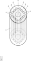
- Figur 2
- eine Vorderansicht auf einen Stator und einen Rotor;
- Figur 3
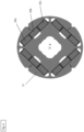
- eine perspektivische Ansicht auf den Rotor gemäß einer ersten Ausführungsform;
- Figur 4
- eine Vorderansicht auf den Rotor gemäß der ersten Ausführungsform;
- Figur 5
- eine Vorderansicht auf den Rotor gemäß einer zweiten Ausführungsform;
- Figur 6
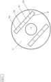
- eine Vorderansicht auf den Rotor gemäß einer dritten Ausführungsform;
- Figur 7
- eine Vorderansicht auf den Rotor gemäß einer vierten Ausführungsform; und
- Figur 8
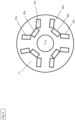
- eine Vorderansicht auf den Rotor gemäß einer fünften Ausführungsform.
-
Figur 1 zeigt eine Werkzeugmaschine 1 gemäß einer beispielhaften Ausführungsform. Die Werkzeugmaschine 1 ist in Form einer akkubetriebenen Bohrmaschine ausgestaltet. - Gemäß einem alternativen Ausführungsbeispiel kann die Werkzeugmaschine auch in Form einer Säge, eines Schleifgeräts, eines Bohrhammers oder dergleichen ausgestaltet sein.
- Die als Bohrmaschine ausgestaltete Werkzeugmaschine 1 enthält dabei im Wesentlichen ein Gehäuse 2, einen Handgriff 3, eine Werkzeugaufnahme 4 und eine Energieversorgung 5.
- Das Gehäuse 2 weist ein vorderes Ende 2a, ein hinteres Ende 2b, ein oberes Ende 2c und ein unteres Ende 2d auf.
- An dem vorderen Ende 2a des Gehäuses 2 ist die Werkzeugaufnahme 4 positioniert. Die Werkzeugaufnahme 4 dient zum Aufnehmen und Halten eines Werkzeugs. In den Figuren ist das Werkzeug nicht dargestellt.
- In dem vorliegenden Ausführungsbeispiel kann das Werkzeug in Form eines Bohrers ausgestaltet. An dem unteren Ende 2d des Gehäuses 2 ist ein erstes Ende 3a des Handgriffs 3 positioniert. An dem zweiten Ende 3b des Handgriffs 3 ist eine Schnittstelle 6 vorgesehen.
- Wie in
Figur 1 gezeigt weist der Handgriff 3 einen Aktivierungsschalter 8 auf, mit dem die Werkzeugmaschine 1 in einen Aktivierungszustand oder Deaktivierungszustand eingestellt werden kann. - An die Schnittstelle 6 kann die Energieversorgung 5 wiederlösbar befestigt werden. In dem vorliegenden Ausführungsbeispiel ist die Energieversorgung 5 in Form eines Akkumulators ausgestaltete. Die Energieversorgung 5 dient zum Versorgen der Werkzeugmaschine mit elektrischer Energie.
- Entsprechend einem alternativen Ausführungsbeispiel kann die Energieversorgung 5 auch als Stromkabel zum Verbinden der Werkzeugmaschine 1 mit einer Netzstromquelle (Steckdose) ausgestaltet sein. Die als Stromkabel ausgestaltete Energieversorgung 5 ist in den Figuren nicht dargestellt.
- Im Inneren des Gehäuses 2 ist im Wesentlichen ein Elektromotor 9 als Antrieb, eine Getriebevorrichtung 10, eine Antriebswelle 11 und eine Steuereinrichtung 12 positioniert.
- Der Elektromotor 9, die Getriebevorrichtung 10, die Antriebswelle 11 und die Werkzeugaufnahme 4 sind so im Inneren des Gehäuses 2 zueinander angeordnet, dass ein in dem Elektromotor 9 erzeugtes Drehmoment auf die Getriebevorrichtung 10, die Antriebswelle 11 und schließlich auf die Werkzeugaufnahme 4 bzw. auf das Werkzeug übertragen werden kann.
- Die Steuereinrichtung 12 ist mittels entsprechenden Leitungen L mit dem Aktivierungsschalter 8, der Akku-Schnittstelle 6 und dem Elektromotor 9 verbunden.
- Der Elektromotor 9 ist in Form eines bürstenlosen Elektromotors ausgestaltet und enthält im Wesentlichen einen Stator 16 und einen Rotor 17, vgl.
Figur 2 . - Die als Akkumulator ausgestaltete Energieversorgung 5 kann mit der Werkzeugmaschine 1 wiederlösbar verbunden werden, um die Werkzeugmaschine 1 mit elektrischer Energie zu versorgen. Der Akkumulator 5 enthält im Wesentlichen ein Akku-Gehäuse 20, eine Anzahl an Energiespeicherzellen 13, eine Akku-Schnittstelle 14 sowie eine Steuerungseinrichtung 15.
- Die Energiespeicherzellen 13 können auch als Akku-Zellen bezeichnet werden und sind im Inneren des Akku-Gehäuses 20 angeordnet.
- Das Akku-Gehäuse 20 enthält dabei im Wesentlichen ein Deckelelement 20a, vier Seitenwände 20b und ein Bodenelement 20c.
- Die Akku-Schnittstelle 14 ist an der Außenseite des Deckelelements 20a angeordnet und dient zum elektrischen bzw. elektronischen sowie mechanischen Verbinden des Akkumulators 5 mit der Werkzeugmaschine 1 oder einer Ladevorrichtung.
- Die Ladevorrichtung dient zum Laden des Akkumulators 5 mit elektrischer Energie und ist in den Figuren nicht dargestellt.
- Zum elektrischen bzw. elektronischen Verbinden weist die Akku-Schnittstelle 14 einen Pluskontakt, einen Minuskontakt und einen Kommunikationskontakt auf. Der Plus- und Minuskontakt dient zur Erzeugen eines Stromkreises, wenn der Akkumulator 5 mit einer Werkzeugmaschine 1 oder einer Ladevorrichtung verbunden ist. Der Kommunikationskontakt dient zum Senden und Empfangen von Daten sowie Informationen in Form von elektrischen Signalen.
- Alternativ oder zusätzlich kann der Akkumulator 5 auch eine Funkkommunikation (z.B. Bluetooth) bzw. drahtlose Kommunikation enthalten.
- Die Energiespeicherzellen 13 dienen zum Aufnehmen, Speichern und erneuten Abgeben elektrischer Energie. Die Energiespeicherzellen 13 sind in zylindrischer Form sowie auf Basis einer Lithium-lonen-Technologie ausgestaltet. Jede Energiespeicherzelle 13 enthält an einem Ende eine Kontakteinrichtung, die zur Übertragung elektrischer Energie dient. Die einzelnen Kontakteinrichtung sind über entsprechende Leitungen mit der Steuerungseinrichtung 15 des Akkumulators 5 verbunden.
- Alternativ können die Energiespeicherzellen 13 auch auf einer anderen geeigneten Technologie basieren.
- Die zylindrische Form der Energiespeicherzellen 13 ist ebenfalls optional, sodass auch jede andere geeignete Form bzw. Geometrie gewählt werden kann. So ist es insbesondere auch möglich, dass die Energiespeicherzellen 13 als Pouchzellen ausgestaltet sind.
- Es ist zudem auch möglich, dass der Akkumulator 5 sowohl zylindrische Energiespeicherzellen 13 als auch Pouch-Zellen enthält. Es ist insbesondere möglich, dass der Akkumulator 5 lediglich eine einzige zylindrische Energiespeicherzelle 13 und eine einzige Pouchzelle enthält.
- Die Steuerungseinrichtung 15 regelt und steuert verschiedene Funktionen des Akkumulators 5. Zu den Funktion gehört unter anderen die Steuerung der Aufnahme und Abgabe von elektrischer Energie in bzw. aus den Energiespeicherzellen 13. Darüber hinaus wird mit Hilfe der Steuerungseinrichtung 15 die Menge an elektrischer Energie gesteuert, die von den Energiespeicherzellen 13 aufgenommen oder abgegeben werden sollen.
- Wie in
Figur 3 angedeutet ist der Rotor 17 im Inneren des Stators 16 positioniert und zudem drehbar zu dem Stator 16 ausgestaltet. - Wie in
Figur 2 gezeigt enthält der Stator 16 ein Statorblechpaket mit sechs radial nach innen gerichtete Polzähne 19. Das Statorblechpaket besteht im Wesentlichen aus einer Anzahl an übereinander gestapelten Profilblechen. - Es sind jeweils zwei Polzähne 19 einander gegenüber positioniert. Gemäß einer alternativen Ausführungsform können auch mehr oder weniger als sechs Polzähne 19 vorgesehen sein. Die Polzähne 19 dienen zum jeweiligen Aufnehmen eines Spulendrahts 21 zum Erzeugen einer Spule 24. Die Spulen 24 sind entsprechend über die Steuereinrichtung 12 mit der Energieversorgung 5 verbunden, um eine elektrische Spannung an die Spulen 24 anzulegen. Mit anderen Worten: die Spulen 24 werden bestromt. Mit Hilfe der Spulen 24 wird ein abwechselndes Magnetfeld MF erzeugt, durch welches der Rotor 17 gedreht wird.
- Wie in
Figur 2 bis 7 gezeigt enthält der Rotor 17 einen zylindrischen Rotorkörper 18 mit einer Anzahl an Permanentmagneten 22. - Der Rotorkörper 18 enthält eine Anzahl an Aussparungen 23, in die jeweils ein Permanentmagnet 22 eingeführt werden kann. Wie in
Figur 3 angedeutet, sind die Permanentmagnete 22 hierdurch gleichmäßig um eine Rotationsachse R angeordnet. - In
Figur 3 und4 ist der Rotor 17 gemäß einer ersten Ausführungsform dargestellt, wobei der Rotorkörper vier Aussparungen 23 aufweist. Es sind dabei jeweils zwei Aussparungen 23 gegenüberliegend und gleichmäßig um die Rotationsachse R positioniert. In jeder Aussparung 23 ist ein erstes, zweites und drittes Magnetsegment 25a, 25b, 25c in einer Reihe angeordnet. - Die Magnetsegmente 25a, 25b, 25c bestehen dabei aus NdFeB (Neodym-Eisen-Bor).
- Das Material des ersten Magnetsegments 25a und dritten Magnetsegments 25c weist eine um mindestens 7% höhere Koerzitivfeldstärke (HCJ) auf als das Material des zweiten Magnetsegments 25b. Mit dem zweiten Magnetsegment 25b ist das mittlere Magnetsegment gemeint, welcher zwischen dem ersten Magnetsegment 25a und dritten Magnetsegment 25c bzw. zwischen den beiden außenliegenden Magnetsegmenten 25a, 25c positioniert ist.
- In
Figur 5 ist der Rotor 17 gemäß einer zweiten Ausführungsform dargestellt. Der Rotor 17 gemäß der zweiten Ausführungsform ist im Wesentlichen identisch zu dem Rotor 17 gemäß der ersten Ausführungsform. Im Unterschied zu der ersten Ausführungsform ist bei der zweiten Ausführungsform in jeder Aussparung ein erstes, zweites, drittes und viertes Magnetsegment 25a, 25b, 25c, 25d in einer Reihe angeordnet. Das Material des ersten Magnetsegments 25a und vierten Magnetsegments 25d weist eine um mindestens 7% höhere Koerzitivfeldstärke (HCJ) auf als das Material des zweiten Magnetsegments 25b und dritten Magnetsegments 25c. - In
Figur 6 ist der Rotor 17 gemäß einer dritten Ausführungsform dargestellt. Der Rotor 17 gemäß der dritten Ausführungsform ist im Wesentlichen identisch zu dem Rotor 17 gemäß der zweiten Ausführungsform. Im Unterschied zu der zweiten Ausführungsform sind bei der dritten Ausführungsform anstelle von vier Aussparungen 23 lediglich zwei Aussparungen 23 vorgesehen. Wie inFigur 6 ersichtlich sind die beiden Aussparungen 23 identisch und um die Rotationsachse R herum angeordnet. In jeder der beiden Aussparung 23 ist ein erstes, zweites, drittes und viertes Magnetsegment 25a, 25b, 25c, 25d in einer Reihe positioniert. - In
Figur 7 ist der Rotor 17 gemäß einer vierten Ausführungsform dargestellt. Der Rotor 17 gemäß der vierten Ausführungsform unterscheidet sich von dem Rotor 17 gemäß der dritten Ausführungsform dadurch, dass jede Aussparung 23 im Wesentlichen V-förmig ausgestaltet ist. Die V-förmige Ausgestaltung einer Aussparung 23 enthält dabei jeweils einen ersten und zweiten Schenkel 23a, 23b welche in einem stumpfen Winkel zueinander positioniert sind. Die Öffnung jeder Aussparung 23 weist dabei in einer radialen Richtung nach außen. Der erste und zweite Schenkel 23a, 23b ist dabei so ausgestaltet, dass jeweils zwei Magnetsegmente 25a, 25b nebeneinander aufgenommen werden können. Gemäß einer weiteren alternativen Ausführungsform kann jeder Schenkel 23a, 23b auch so ausgestaltete sein, dass mehr als zwei Magnetsegmente 25a, 25b aufgenommen werden können. - In
Figur 8 ist der Rotor 17 gemäß einer fünften Ausführungsform dargestellt. Der Rotor 17 gemäß der fünften Ausführungsform unterscheidet sich von dem Rotor 17 gemäß der vierten Ausführungsform dadurch, dass jede Aussparung 23 im Wesentlichen U-förmig ausgestaltet ist. - Die U-förmige Ausgestaltung einer Aussparung 23 enthält dabei jeweils einen ersten, zweiten und dritten Abschnitt 26a, 26b, 26c. Die Öffnung 27a, 27b jeder Aussparung 23 weist dabei in einer radialen Richtung nach außen. Jeder der drei Abschnitte 26a, 26b, 26c ist dabei so ausgestaltet, dass jeweils ein Magnetsegment 25a. 25b, 25c aufgenommen werden kann. Entsprechend einer weiteren alternativen Ausführungsform kann jeder Abschnitt auch mehr als ein Magnetsegment aufnehmen.
- Gemäß einer alternativen Ausführungsform kann das Material des ersten Magnetsegments 25a und dritten Magnetsegments 25c bzw. der jeweils außenliegenden Magnetsegments 25a, 25c ab einem Abstand von 1 mm von einer Magnetsegmentoberfläche eine um mindestens 7% höhere Koerzitivfeldstärke aufweisen als das Material des zweiten Magnetsegments 25b bzw. mittleren Magnetsegments 25b.
- Die Entmagnetisierung der Magnetsegmente kann durch Korngrenzen-Diffusionsprozess, der sogenannte GBD-Prozess, erreicht werden.
-
- 1
- Werkzeugmaschine
- 2
- Gehäuse
- 2a
- vorderes Ende des Gehäuses
- 2b
- hinteres Ende des Gehäuses
- 2c
- oberes Ende des Gehäuses
- 2d
- unteres Ende des Gehäuses
- 3
- Handgriff
- 3a
- erstes Ende des Handgriffs
- 3b
- zweites Ende des Handgriffs
- 4
- Werkzeugaufnahme
- 5
- Energieversorgung
- 6
- Schnittstelle
- 8
- Aktivierungsschalter
- 9
- Elektromotor
- 10
- Getriebevorrichtung
- 11
- Antriebswelle
- 12
- Steuereinrichtung
- 13
- Energiespeicherzelle
- 14
- Akku-Schnittstelle
- 15
- Steuerungseinrichtung
- 16
- Stator
- 17
- Rotor
- 18
- Rotorkörper
- 19
- Polzahn
- 20
- Akku-Gehäuse
- 21
- Spulendraht
- 22
- Permanentmagnet
- 23
- Aussparung
- 24
- Spule
- 25a
- erstes Magnetsegment
- 25b
- zweites Magnetsegment
- 25c
- drittes Magnetsegment
- 25d
- viertes Magnetsegment
- 26a
- erster Abschnitt einer Aussparung
- 26b
- zweiter Abschnitt einer Aussparung
- 26c
- dritter Abschnitt einer Aussparung
- R
- Rotationsachse
Claims (11)
- Rotor (17) für einen Elektromotor (9), insbesondere als Antrieb für eine Werkzeugmaschine (1),
gekennzeichnet durch einen Rotorkörper (18) mit wenigstens einem ersten und zweiten um eine Rotationsachse (R) angeordneten Permanentmagnet (22), wobei jeder Permanentmagnet (22) wenigstens ein erstes, zweites und drittes in einer Reihe angeordnetes Magnetsegment (25a, 25b, 25c) enthält, und wobei das Material des ersten und dritten Magnetsegments (25a, 25c) eine um mindestens 7% höhere Koerzitivfeldstärke (HCJ) aufweist als das Material des zweiten Magnetsegments (25b). - Rotor (17) nach Anspruch 1,
dadurch gekennzeichnet, dass das Material des zweiten Magnetsegments (25b) eine um mindestens 5% höhere Remanenzflussdichte aufweist als das Material des ersten oder dritten Magnetsegments (25a, 25c). - Rotor (17) nach Anspruch 1 oder 2,
dadurch gekennzeichnet, dass das Material des ersten und dritten Magnetsegments (25a, 25c) eine um mindestens 7 bis 15% höhere Koerzitivfeldstärke aufweist als das Material des zweiten Magnetsegments. - Rotor (17) nach wenigstens einem der Ansprüche 1 bis 3,
dadurch gekennzeichnet, dass das Material des zweiten Magnetsegments (25b) eine um mindestens 5 bis 10% höhere Remanenzflussdichte aufweist als das Material des ersten oder dritten Magnetsegments (25a, 25c). - Rotor (17) nach wenigstens einem der Ansprüche 1 bis 4,
dadurch gekennzeichnet, dass das Volumen eines ersten und dritten Magnetsegments (25a, 25c) zwischen 10% und 35% des aufsummierten Volumens aller Magnetsegmente (25a, 25b, 25c) des wenigstens ersten oder zweiten Permanentmagneten (22) aufweist. - Rotor (17) nach wenigstens einem der Ansprüche 1 bis 5,
dadurch gekennzeichnet, dass die Magnetsegmente (25a, 25b, 25c, 25d) voneinander elektrisch isoliert sind. - Rotor (17) nach wenigstens einem der Ansprüche 1 bis 6,
dadurch gekennzeichnet, dass benachbarte Magnetsegmente (22) miteinander verklebt sind. - Rotor (17) nach wenigstens einem der Ansprüche 1 bis 7,
dadurch gekennzeichnet, dass das Material des ersten und dritten Magnetsegments (25a, 25c) ab einem Abstand von 1 mm von wenigstens einer Magnetsegmentoberfläche eine um mindestens 7% höhere Koerzitivfeldstärke aufweist als das Material des zweiten Magnetsegments (25b). - Rotor (17) nach wenigstens einem der Ansprüche 1 bis 8,
dadurch gekennzeichnet, dass die Magnetsegmente (25a, 25b, 25c, 25d) eines polbildenden Permanentmagnets (22) im Wesentlichen V- oder U-förmig angeordnet sind. - Elektromotor mit einem Rotor (17) nach wenigstens einem der Ansprüche 1 bis 9.
- Werkzeugmaschine mit einem Rotor (17) nach wenigstens einem der Ansprüche 1 bis 9.
Priority Applications (3)
| Application Number | Priority Date | Filing Date | Title |
|---|---|---|---|
| EP23207998.8A EP4550627A1 (de) | 2023-11-06 | 2023-11-06 | Magnetsegmente für einen rotor |
| CN202480063084.5A CN121942115A (zh) | 2023-11-06 | 2024-10-22 | 用于转子的磁体段 |
| PCT/EP2024/079798 WO2025098760A1 (de) | 2023-11-06 | 2024-10-22 | Magnetsegmente für einen rotor |
Applications Claiming Priority (1)
| Application Number | Priority Date | Filing Date | Title |
|---|---|---|---|
| EP23207998.8A EP4550627A1 (de) | 2023-11-06 | 2023-11-06 | Magnetsegmente für einen rotor |
Publications (1)
| Publication Number | Publication Date |
|---|---|
| EP4550627A1 true EP4550627A1 (de) | 2025-05-07 |
Family
ID=88731462
Family Applications (1)
| Application Number | Title | Priority Date | Filing Date |
|---|---|---|---|
| EP23207998.8A Withdrawn EP4550627A1 (de) | 2023-11-06 | 2023-11-06 | Magnetsegmente für einen rotor |
Country Status (3)
| Country | Link |
|---|---|
| EP (1) | EP4550627A1 (de) |
| CN (1) | CN121942115A (de) |
| WO (1) | WO2025098760A1 (de) |
Citations (4)
| Publication number | Priority date | Publication date | Assignee | Title |
|---|---|---|---|---|
| JP2010004673A (ja) * | 2008-06-20 | 2010-01-07 | Toshiba Corp | 永久磁石式回転電機 |
| US20100225191A1 (en) * | 2009-03-06 | 2010-09-09 | Hyundai Motor Japan R&D Center, Inc. | Rotor having embedded permanent magnet |
| US20120181970A1 (en) * | 2006-07-24 | 2012-07-19 | Kabushiki Kaisha Toshiba | Variable-flux motor drive system |
| JP2012228072A (ja) * | 2011-04-20 | 2012-11-15 | Mitsubishi Electric Corp | 永久磁石型回転電機およびその製造方法 |
-
2023
- 2023-11-06 EP EP23207998.8A patent/EP4550627A1/de not_active Withdrawn
-
2024
- 2024-10-22 CN CN202480063084.5A patent/CN121942115A/zh active Pending
- 2024-10-22 WO PCT/EP2024/079798 patent/WO2025098760A1/de active Pending
Patent Citations (4)
| Publication number | Priority date | Publication date | Assignee | Title |
|---|---|---|---|---|
| US20120181970A1 (en) * | 2006-07-24 | 2012-07-19 | Kabushiki Kaisha Toshiba | Variable-flux motor drive system |
| JP2010004673A (ja) * | 2008-06-20 | 2010-01-07 | Toshiba Corp | 永久磁石式回転電機 |
| US20100225191A1 (en) * | 2009-03-06 | 2010-09-09 | Hyundai Motor Japan R&D Center, Inc. | Rotor having embedded permanent magnet |
| JP2012228072A (ja) * | 2011-04-20 | 2012-11-15 | Mitsubishi Electric Corp | 永久磁石型回転電機およびその製造方法 |
Also Published As
| Publication number | Publication date |
|---|---|
| CN121942115A (zh) | 2026-04-28 |
| WO2025098760A1 (de) | 2025-05-15 |
Similar Documents
| Publication | Publication Date | Title |
|---|---|---|
| DE112011103838B4 (de) | Rotor und Motor | |
| DE112011100218B4 (de) | Drehende Elektromaschine | |
| DE102012100668A1 (de) | Elektromotor | |
| EP1843454B1 (de) | Getriebeeinheit und Werkzeughalter mit einer derartigen Getriebeeinheit | |
| EP1695429B1 (de) | Elektrische maschine | |
| DE112017000288B4 (de) | Stator für elektrische Rotationsmaschine und elektrische Rotationsmaschine, die ihn verwendet | |
| DE102006022836A1 (de) | Statoranordnung und Rotoranordnung für eine Transversalflußmaschine | |
| WO2010054651A2 (de) | Elektrische maschine | |
| DE102012216496A1 (de) | Handwerkzeugmaschine | |
| DE102020129142A1 (de) | Läufer für eine rotierende elektrische Maschine | |
| EP4441869A1 (de) | Elektromotor, werkzeugmaschine und system, das eine werkzeugmaschine und eine energieversorgungsvorrichtung umfasst | |
| DE102020105651A1 (de) | Zykloiden-reluktanzmotor mit rotor-permanentmagneten | |
| DE102020105640A1 (de) | Zykloiden-reluktanzmotor mit rotor-elektromagneten | |
| DE102017127611A1 (de) | Synchron-Reluktanzmotor mit durch Permanentmagnete gesättigtem magnetischen Nebenschlusspfad | |
| DE112021007306T5 (de) | Rotor für rotierende elektrische maschine und rotierende elektrische maschine | |
| DE102006053973B4 (de) | Elektrischer Generator | |
| EP4550627A1 (de) | Magnetsegmente für einen rotor | |
| EP0664599B1 (de) | Kommutatormotor | |
| DE102009024910A1 (de) | Elektromotor | |
| WO2022268513A1 (de) | Werkzeugmaschine und verfahren zum betrieb einer werkzeugmaschine | |
| EP4651342A1 (de) | Magnetsegmente für einen rotor | |
| EP4614767A1 (de) | Rotor mit wiederlösbaren magneten | |
| EP4481996A1 (de) | Klemmvorrichtung für einen stator | |
| EP4597801A1 (de) | Stator mit mehreren anschlüssen | |
| EP4503403A1 (de) | Integrierter widerstand in einen elektronikkühlkörper |
Legal Events
| Date | Code | Title | Description |
|---|---|---|---|
| PUAI | Public reference made under article 153(3) epc to a published international application that has entered the european phase |
Free format text: ORIGINAL CODE: 0009012 |
|
| STAA | Information on the status of an ep patent application or granted ep patent |
Free format text: STATUS: THE APPLICATION HAS BEEN PUBLISHED |
|
| AK | Designated contracting states |
Kind code of ref document: A1 Designated state(s): AL AT BE BG CH CY CZ DE DK EE ES FI FR GB GR HR HU IE IS IT LI LT LU LV MC ME MK MT NL NO PL PT RO RS SE SI SK SM TR |
|
| STAA | Information on the status of an ep patent application or granted ep patent |
Free format text: STATUS: THE APPLICATION IS DEEMED TO BE WITHDRAWN |
|
| 18D | Application deemed to be withdrawn |
Effective date: 20251108 |