EP4550636A1 - Statorwicklungsverbinder, statorwicklung und elektromotor - Google Patents
Statorwicklungsverbinder, statorwicklung und elektromotor Download PDFInfo
- Publication number
- EP4550636A1 EP4550636A1 EP22949100.6A EP22949100A EP4550636A1 EP 4550636 A1 EP4550636 A1 EP 4550636A1 EP 22949100 A EP22949100 A EP 22949100A EP 4550636 A1 EP4550636 A1 EP 4550636A1
- Authority
- EP
- European Patent Office
- Prior art keywords
- conductor
- avoidance
- connector
- connector body
- stator winding
- Prior art date
- Legal status (The legal status is an assumption and is not a legal conclusion. Google has not performed a legal analysis and makes no representation as to the accuracy of the status listed.)
- Pending
Links
Images



Classifications
-
- H—ELECTRICITY
- H02—GENERATION; CONVERSION OR DISTRIBUTION OF ELECTRIC POWER
- H02K—DYNAMO-ELECTRIC MACHINES
- H02K3/00—Details of windings
- H02K3/04—Windings characterised by the conductor shape, form or construction, e.g. with bar conductors
- H02K3/28—Layout of windings or of connections between windings
-
- H—ELECTRICITY
- H02—GENERATION; CONVERSION OR DISTRIBUTION OF ELECTRIC POWER
- H02K—DYNAMO-ELECTRIC MACHINES
- H02K15/00—Processes or apparatus specially adapted for manufacturing, assembling, maintaining or repairing of dynamo-electric machines
- H02K15/30—Manufacture of winding connections
- H02K15/33—Connecting winding sections; Forming leads; Connecting leads to terminals
- H02K15/35—Form-wound windings
-
- H—ELECTRICITY
- H02—GENERATION; CONVERSION OR DISTRIBUTION OF ELECTRIC POWER
- H02K—DYNAMO-ELECTRIC MACHINES
- H02K3/00—Details of windings
- H02K3/04—Windings characterised by the conductor shape, form or construction, e.g. with bar conductors
- H02K3/12—Windings characterised by the conductor shape, form or construction, e.g. with bar conductors arranged in slots
-
- H—ELECTRICITY
- H02—GENERATION; CONVERSION OR DISTRIBUTION OF ELECTRIC POWER
- H02K—DYNAMO-ELECTRIC MACHINES
- H02K3/00—Details of windings
- H02K3/46—Fastening of windings on the stator or rotor structure
-
- H—ELECTRICITY
- H02—GENERATION; CONVERSION OR DISTRIBUTION OF ELECTRIC POWER
- H02K—DYNAMO-ELECTRIC MACHINES
- H02K3/00—Details of windings
- H02K3/46—Fastening of windings on the stator or rotor structure
- H02K3/50—Fastening of winding heads, equalising connectors, or connections thereto
-
- H—ELECTRICITY
- H02—GENERATION; CONVERSION OR DISTRIBUTION OF ELECTRIC POWER
- H02K—DYNAMO-ELECTRIC MACHINES
- H02K2203/00—Specific aspects not provided for in the other groups of this subclass relating to the windings
- H02K2203/09—Machines characterised by wiring elements other than wires, e.g. bus rings, for connecting the winding terminations
Definitions
- the present invention relates to the field of electric motors, and more particularly to a stator winding connector, a stator winding and an electric motor.
- Stator windings in most existing flat wire motors are categorized into hairpin and I-pin ones.
- a hairpin winding is made up of conductor groups, each of which is a U-shaped integral structure resembling a hairpin and formed by bending and twisting a conductor. Hairpin windings suffer from difficult insertion of conductors into stator slots, which slows down the manufacturing process.
- each conductor group in an I-pin winding includes a first conductor and a second conductor, which are separate from each other before they are inserted into a stator slot. The first and second conductors may be separately inserted into the stator slot and then connected together end-to-end. Therefore, conductors in I-pin windings can be more easily inserted into stator slots, enabling faster manufacturing.
- the connecting end portion is a modified conductor end portion, which increases a clearance between adjacent conductors in a conductor group to enable a winding to have a creepage distance required by an electric motor.
- the stator winding connector overcomes the problem of an inadequate creepage distance between connected conductors in existing windings.
- the stator winding connector is adapted to be provided on a conductor in a winding and includes a connector body defining, on its opposite sides, a connecting surface and a first avoidance surface, the first avoidance surface configured so that, when a single conductor group including first and second conductors both provided with such connectors is mounted in a stator slot of a stator at relatively fixed positions, the connector body of any of the conductors does not protrude beyond an insulating layer on the other conductor.
- the connector body may further define a first side wall surface and a second avoidance surface in the first side wall surface, the second avoidance surface configured so that when the first and second conductors are mounted in the stator slot at the relatively fixed positions, the first side wall surface of the connector body of the first conductor radially opposes the first side wall surface of the connector body of the second conductor and that the first side wall surface of the connector body of each of the conductors is spaced, on a side proximal to a free end of the connector, from the other conductor by a radial gap in a radial direction of the stator.
- the connector body may further have an end surface at the free end thereof, wherein the second avoidance surface is joined to the end surface.
- the second avoidance surface may be located between and join the connecting surface and the first avoidance surface.
- the second avoidance surface may be curved so that, as a middle portion of the second avoidance surface of the connector body of each of the first and second conductors approaches the end surface of the connector body, the radial gap gradually enlarges.
- first avoidance surface may be joined to the end surface.
- connecting surface may be joined to the end surface.
- the first avoidance surface may be curved so as to be spaced from the connecting surface by a distance, which gradually decreases in a direction approaching the end surface.
- the present invention also provides a stator winding including a number of conductors each provided thereon with the stator winding connector as defined above.
- the present invention also provides an electric motor including the stator winding as defined above.
- the present invention provides a stator winding connector including a connector body defining, on its opposite sides, a connecting surface and a first avoidance surface.
- the first avoidance surface is configured so that the connector body, when connected to a connector body of an adjacent conductor, does not protrude beyond an insulating layer on the adjacent conductor.
- first avoidance surfaces on the side opposite to the connecting surfaces enables avoidance of interference, and an increased clearance, between the adjacent conductors in the conductor group, which allows the winding to satisfy a creepage distance requirement of an electric motor.
- first avoidance surfaces enable avoidance of interference of each conductor with the insulating layer on the adjacent conductor, during bending and twisting of the conductors at the connecting end portions, any conductor will not come into contact with the insulating layer on the adjacent conductor, avoiding causing damage to the insulating layers.
- X-shaped crosses will be formed by connecting ends of adjacent conductors, circumventing the problem of excessively raised conductor end portions.
- stator winding connector proposed in present invention will be described in greater detail below with reference to the accompanying drawings, which illustrate specific embodiments thereof. From the following description, advantages and features of the present invention will become more apparent. Note that the figures are provided in a very simplified form not necessarily drawn to exact scale for the only purpose of helping to explain the disclosed embodiments in a more convenient and clearer way.
- the terms “mounting”, “coupling”, “connecting”, “disposing” and any variants thereof should be interpreted in a broad sense.
- this is generally intended to only mean that there is a connection, coupling, engagement or transmission relationship between the two elements, which may be either direct or indirect with one or more intervening elements, and should not be interpreted as indicating or implying a particular spatial position relationship between them. That is, the element may be located inside, outside, above, under, beside, or at any other location relative to the other element, unless the context clearly dictates otherwise.
- Those of ordinary skill in the art can understand the specific meanings of the above-mentioned terms herein, depending on their context.
- each conductor group in an existing I-pin winding, includes a first conductor 41 and a second conductor 42.
- the first conductor 41 and the second conductor 42 each have a bent end portion.
- the first conductor 41 and the second conductor 42 can be inserted into a stator slot so that the end portions of them are oriented substantially in parallel to each other.
- the two end portions are then connected to each other by laser welding.
- This connection approach requires the connecting end portions to be bent for a second time and therefore suffers from multiple bending processes. Further, the resulting winding overhang tends to be excessively raised.
- a new connection approach differing from the above approach has been proposed, in which end portions of first and second conductors in conductor groups are processed into bare connecting end portions, which can be connected without being bent so as to be substantially parallel to each other as shown in Fig. 1 .
- This can not only save one bending process, but can also solve the problem of excessively raised conductor end portions.
- the approach of Fig. 2 only takes into account connecting surfaces of the connecting end portions of the first and second conductors in the conductor groups, and these connecting end portions cross to form substantially X-shaped structures.
- one connecting end portion may protrude so that its free end goes beyond an insulating layer on the other conductor.
- this may lead to a too small clearance between the first and second conductor groups 20, 30, which may not able to meet a creepage distance requirement of an electric motor.
- this tends to cause damage to the insulating layers.
- the connecting end portion of the first conductor 41 may protrude so that its free end goes beyond the insulating layer 421 on the second conductor 42. This may lead to a too small clearance between the first and second conductor groups 20, 30.
- stator winding connector proposed herein overcomes the problem of an inadequate creepage distance between connected conductors in existing windings.
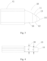
- the stator winding connector is adapted to be provided on a conductor in a winding and includes a connector body 10 defining a connecting surface 11 and a first avoidance surface 12.
- the first avoidance surface 12 is positioned opposite the connecting surface 11.
- the first avoidance surface 12 is configured so that when a single conductor group including a first conductor 41 and a second conductor 42, both provided with such connectors, are mounted in a stator slot at relatively fixed positions, the connector body of any of the conductors does not protrude beyond an insulating layer on the other conductor.
- the first and second conductors belong to a single conductor group.
- the first and second conductors are of the same structure.
- the second conductor 42 is a flat rod provided with an insulating layer 421 on its exterior.
- the insulating layer on an end portion of the second conductor 42 is stripped away, and the end portion is then processed into said connector 10.
- the second conductor 42 is inserted into the stator slot by passing its trailing end through the stator slot so that it protrudes outside from the other side of the stator slot.
- the connector of the second conductor 42 is not inserted in the stator slot.
- the connector of the second conductor 42 is adapted to be connected to the connector of the first conductor 41 that belongs to the same conductor group as the second conductor 42.
- the first conductor 41 and the second conductor 42 are inserted in the stator slot and fixed at the relative positions so that the connecting surfaces 11 of the first conductor 41 and the second conductor 42 are substantially coplanar.
- a laser welding process may be then carried out to form a weld layer, which covers both connecting surfaces and joins the two conductor end portions to each other.
- the present invention is not limited to any particular shape of the connecting surface 11 and first avoidance surface 12.
- they may be planar. In an alternative implementation, they may be curved.
- Each of the connecting surface and the first avoidance surface may either consist of a single flat surface, or be a complex composite surface consisting of multiple surfaces.
- the first avoidance surface and the connecting surface are located on opposite sides.
- the first avoidance surfaces can avoid interference between the adjacent conductors so that, when the first conductor 41 and the second conductor 42 are mounted in the stator slot at the relatively fixed positions, the connector body of the first conductor 41 does not protrude beyond the insulating layer on the second conductor 42 and that the connector body of the second conductor 42 does not protrude beyond the insulating layer on the first conductor 41.
- the connector body of the first conductor 41 is spaced from the insulating layer on the second conductor 42 at a distance a, allowing an increased clearance to be formed between the first conductor group 20 and the second conductor group 30, which facilitates the satisfaction of a creepage distance requirement of an electric motor.
- the vertically opposite connecting surface 11 and first avoidance surface 12 may be asymmetrical and both curved.
- the connecting surface 11 may be more steeply sloped and hence have a greater length, ensuring a sufficient weld length.
- the first avoidance surface may have a gentler slope, which enables adequate avoidance while not adversely affecting the length of the connecting surface.
- the vertically opposite connecting surface 11 and the first avoidance surface 12 are symmetric, the connecting surface 11 and the first avoidance surface 12 are both curved, facilitating manufacturing.
- the connecting surface 11 is curved, and the first avoidance surface 12 is a cut surface.
- the first avoidance surface 12 may be planar.
- the connecting surface 11 is curved
- the first avoidance surface 12 is a composite cut surface.
- the first avoidance surface 12 may be a composite surface consisting of a first flat surface 121 and a second flat surface 122.
- connecting surface and the first avoidance surface While not enumerated herein, many other forms are possible for the connecting surface and the first avoidance surface.
- the forms of these surfaces may be particularly adapted according to dimensions of the connector and an intended use condition of an electric motor employing the connector.
- adding the first avoidance surfaces on the side opposite to the connecting surfaces enables avoidance of interference, and an increased clearance, between the adjacent conductors in the conductor group, which allows the winding to satisfy a creepage distance requirement of an electric motor.
- the first avoidance surfaces enable avoidance of interference of each conductor with the insulating layer on the adjacent conductor, during bending and twisting of the conductors at the connecting end portions, any conductor will not come into contact with the insulating layer on the adjacent conductor, avoiding causing damage to the insulating layers.
- Such connectors can be used to modify conductor connections in conductor groups from an I-pin to X-pin configuration, solving the problem of an excessively raised overhang of existing I-pin windings and simplifying electric motor assembly.
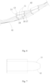
- the connector body 10 may further have a first side wall surface 16 and a second avoidance surface 13, the second avoidance surface 13 is in the first side wall surface 16.
- the second avoidance surface 13 is configured in the way as described below.
- the first side wall surface of the connector body of the first conductor 41 radially opposes the first side wall surface of the connector body of the second conductor 42, and the second avoidance surfaces create radial gaps in a radial direction of the stator, which space the first side wall surface of the connector body of each conductor at the side of the connector closer to a free end thereof from the other conductor.
- the free end refers to an end of the connector body in a lengthwise direction of the conductor. Since the connector body is actually a depending structure defined by the conductor end portion, it is apparent that the free end is a depending end of the connector body.
- the second avoidance surface 13 may be formed by cutting away material at the first side wall surface 16. Due the presence of the second avoidance surface, a thickness L1 of the connector body 10 at the free end is smaller than a thickness L2 of the connector body 10 at its middle portion.
- both a first avoidance region 17 and a second avoidance region 18, i.e., the aforementioned radial gaps, are formed between the first side wall surface 16 of the connector body of the first conductor 41 and the first side wall surface 16 of the connector body of the second conductor 42.
- the first conductor 41 and the second conductor 42 in the conductor group are inserted in the stator slot and fixed at the relative positions, due to the presence of the first avoidance region 17, the first side wall surface of the connector body of the first conductor 41 does not contact, at the side closer to the connector's free end, the end of the connector body of the second conductor 42 proximate the insulating layer thereon.
- the first side wall surface of the connector body of the second conductor 42 does not contact, at the side closer to the connector's free end, the end of the connector body of the first conductor 41 proximate the insulating layer thereon.
- a third avoidance surface 15 may be formed on the side opposite to the second avoidance surface 13 by appropriate processing.
- the second avoidance surface 13 and the third avoidance surface 15 may be mirror-symmetric surfaces for avoiding interference with adjacent other conductors in corresponding directions.
- the first conductor 41 and the second conductor 42 are mounted in the stator slot at the relatively fixed positions
- the first conductor 41 and the second conductor 42 are mounted in the stator slot so that the connector bodies of the first conductor 41 and the second conductor 42 are located at the relatively fixed positions before they are connected to each other.
- This enables the two connector bodies to be desirably positioned as required by the subsequent connecting process.
- the first conductor 41 and the second conductor 42 are inserted in the stator slot, and the two connecting end portions are then twisted so as to be located at the relatively fixed positions, followed by joining the two connector bodies together by laser welding.
- the present invention is not limited to any particular shape of the second avoidance surface.
- it may be planar. In an alternative implementation, it may be curved.
- the second avoidance surface may either consist of a single flat surface, or be a complex composite surface consisting of multiple surfaces.
- the connector body 10 has an end surface 14, the end surface 14 is positioned at the free end of the connector body 10, the second avoidance surface 13 is joined to the end surface 14.
- the second avoidance surface and the end surface may be joined by a curved transition.
- the end surface 14 is actually at the depending end of the connector body 10, and the joining of the second avoidance surface 13 to the depending end of the connector body 10 means a maximized length of the avoidance region defined by the second avoidance surface 13 and adjacency of the avoidance region to the end surface. In this way, as shown in Fig.
- the end surface 14 of the connector body of the second conductor 42 is closest to the insulating layer on the first conductor 41, and due to the joining of the second avoidance surface 13 to the end surface, the second avoidance region 18 just opposes a portion of the connector body of the first conductor 41 proximate the insulating layer. This enables exact avoidance of interference of the connector body of the second conductor 42 with the insulating layer on the first conductor 41, as well as of the connector body of the first conductor 41 with the insulating layer on the second conductor 42, without removing too much material.
- the second avoidance surface 13 may be located between and join the connecting surface 11 and the first avoidance surface 12.
- the connecting surface 11 is typically located on the side away from an iron core of the stator along an axis of the iron core. In this way, the connecting surface faces outwardly and can be easily welded.
- the connecting surface 11 of the connector body 10 faces substantially upwards, while the first avoidance surface 12 of the connector body 10 faces substantially downwards. Accordingly, in the orientation of Fig.
- the first side wall surface 16 and the second avoidance surface 13 are located on the side of the connector body 10 of the first conductor 41 behind the drawing plane in the direction perpendicular to the paper plane.
- the second avoidance surface 13 joins the connecting surface 11 and the first avoidance surface 12 such as to define an avoidance region extending in the direction perpendicular to the paper plane along the first side wall surface 16 on the side of the connector body 10 behind the drawing plane as viewed in the orientation of Fig. 5 .
- the avoidance region defined by the second avoidance surface 13 has a great extent, which facilitates avoiding interference with the insulating layer on the second conductor 42 in the same conductor group and machining of the structure with the second avoidance surface 13 joining the connecting surface 11 and the first avoidance surface 12.
- the second avoidance surface 13 is curved, the second avoidance surface 13 is further configured, in each of the first conductor 41 and the second conductor 42, the second avoidance surface 13 of the connector body may be curved in such a manner that the corresponding radial gap gradually enlarges as a middle portion of the second avoidance surface approaches the end surface of the connector body.
- a distance between the second avoidance surface 13 and the opposite surface may gradually vary from L2 to L1. Accordingly, with continued reference to Fig. 6 , the joint of the second avoidance surface 13 and the end surface of the connector body of the second conductor 42 is spaced from the connector body of the first conductor 41 at a maximum radial distance. With this arrangement, even when middle portions of the two connector bodies radially come into contact with each other due to manufacturing or mounting tolerances, the curved shape of the second avoidance surface 13 can still ensure that the second conductor 42 is radially spaced apart, at the joint of the second avoidance surface and the end surface, from the connector body of the first conductor 41, effectively avoiding the insulating layer from being scratched and damaged.
- first avoidance surface 12 may be joined to the same end surface 14.
- the avoidance region defined by the first avoidance surface 12 can be lengthened as much as possible, and the provision of the first avoidance surface 12 does not adversely affect the connecting surface 11, ensuring a sufficiently long weld length of the connecting surface.
- the connector body 10 would have a too short length, possibly leading to an insufficient weld length of the connecting surface 11.
- connecting surface 11 may be joined to the end surface 14.
- joining the connecting surface 11 to the end surface 14 enables the connecting surface to have a great length and hence a sufficiently long weld length.
- first avoidance surface 12 is curved
- first avoidance surface 12 is further configured that the first avoidance surface 12 is curved in such a manner that a distance between the first avoidance surface 12 and the connecting surface 11 gradually decreases in the direction approaching the end surface 14.
- the curved shape of the first avoidance surface 12 better ensures that the connector body of each conductor in the conductor group does not protrude beyond the insulating layer on the other conductor.
- Embodiments of the present invention further provide a stator winding including a number of conductors provided thereon with the stator winding connector as defined above.
- the connectors of the conductors are connected in pairs to form conductor groups, which function in the same way as those in a hairpin winding.
- the stator winding incorporating these conductors is an X-pin winding modified from an I-pin winding.
- the conductors are mounted in stator slots and their leading and trailing ends may be connected according to any suitable method known in the art, which is, however, not described in detail here, in order to avoid obscuring the present invention.
- Embodiments of the present invention further provide an electric motor employing the stator winding as defined above.
- the electric motor may include a stator assembly and a rotor assembly arranged on an inner side of the stator assembly.
- the X-pin stator winding that is modified from an I-pin winding may be included in the stator assembly of the electric motor.
Landscapes
- Engineering & Computer Science (AREA)
- Power Engineering (AREA)
- Manufacturing & Machinery (AREA)
- Insulation, Fastening Of Motor, Generator Windings (AREA)
Applications Claiming Priority (2)
| Application Number | Priority Date | Filing Date | Title |
|---|---|---|---|
| CN202210770659.XA CN117375281A (zh) | 2022-06-30 | 2022-06-30 | 定子绕组连接头、定子绕组及电机 |
| PCT/CN2022/134929 WO2024001020A1 (zh) | 2022-06-30 | 2022-11-29 | 定子绕组连接头、定子绕组及电机 |
Publications (2)
| Publication Number | Publication Date |
|---|---|
| EP4550636A1 true EP4550636A1 (de) | 2025-05-07 |
| EP4550636A4 EP4550636A4 (de) | 2025-10-01 |
Family
ID=89383927
Family Applications (1)
| Application Number | Title | Priority Date | Filing Date |
|---|---|---|---|
| EP22949100.6A Pending EP4550636A4 (de) | 2022-06-30 | 2022-11-29 | Statorwicklungsverbinder, statorwicklung und elektromotor |
Country Status (3)
| Country | Link |
|---|---|
| EP (1) | EP4550636A4 (de) |
| CN (1) | CN117375281A (de) |
| WO (1) | WO2024001020A1 (de) |
Family Cites Families (9)
| Publication number | Priority date | Publication date | Assignee | Title |
|---|---|---|---|---|
| KR101976213B1 (ko) * | 2012-12-26 | 2019-05-07 | 현대모비스 주식회사 | 헤어핀 권선모터의 고정자 어셈블리 |
| JP5842856B2 (ja) * | 2013-04-08 | 2016-01-13 | 株式会社デンソー | 回転電機の固定子 |
| JP6593315B2 (ja) * | 2016-12-14 | 2019-10-23 | トヨタ自動車株式会社 | 回転電機 |
| JP2018117469A (ja) * | 2017-01-19 | 2018-07-26 | 本田技研工業株式会社 | 回転電機のステータ |
| CN109586448A (zh) * | 2017-09-29 | 2019-04-05 | 比亚迪股份有限公司 | 导体段及具有其的定子组件、电机 |
| CN109586445A (zh) * | 2017-09-29 | 2019-04-05 | 比亚迪股份有限公司 | 导体段及具有其的定子组件、电机 |
| WO2021144900A1 (ja) * | 2020-01-15 | 2021-07-22 | 株式会社 東芝 | 固定子および固定子の製造方法 |
| CN213661299U (zh) * | 2020-10-30 | 2021-07-09 | 比亚迪股份有限公司 | 定子组件和电机 |
| CN213484604U (zh) * | 2020-10-30 | 2021-06-18 | 比亚迪股份有限公司 | 定子组件和电机 |
-
2022
- 2022-06-30 CN CN202210770659.XA patent/CN117375281A/zh active Pending
- 2022-11-29 EP EP22949100.6A patent/EP4550636A4/de active Pending
- 2022-11-29 WO PCT/CN2022/134929 patent/WO2024001020A1/zh not_active Ceased
Also Published As
| Publication number | Publication date |
|---|---|
| CN117375281A (zh) | 2024-01-09 |
| WO2024001020A1 (zh) | 2024-01-04 |
| EP4550636A4 (de) | 2025-10-01 |
Similar Documents
| Publication | Publication Date | Title |
|---|---|---|
| CN103683617B (zh) | 旋转电机的定子及该定子的制造方法 | |
| KR102255327B1 (ko) | 헤어핀 권선모터의 고정자 어셈블리 | |
| CN105453388A (zh) | 旋转电机 | |
| CN110190693A (zh) | 旋转电机的定子 | |
| CN218569963U (zh) | 定子绕组导体、定子绕组及电机 | |
| US12445006B2 (en) | Insulation assemblies and members for a stator of an electric motor | |
| CN112994304B (zh) | 旋转电机 | |
| CN111279584B (zh) | 旋转电机的电枢铁芯以及旋转电机的电枢铁芯的制造方法 | |
| JP5278440B2 (ja) | ステータ及びその製造方法 | |
| JP6279802B1 (ja) | セグメントコイル用分割導体及びその製造方法 | |
| EP4459847A1 (de) | Wickelkopfbearbeitungsverfahren, wickelkopfstruktur und statoranordnung | |
| EP4550636A1 (de) | Statorwicklungsverbinder, statorwicklung und elektromotor | |
| CN107846086B (zh) | 马达定子及其制造方法 | |
| JP6486545B2 (ja) | 回転電機のステータ、これを用いた回転電機、および回転電機のステータの製造方法 | |
| CN109818443B (zh) | 旋转电机的定子及其组装方法 | |
| JP7465170B2 (ja) | 電磁部品の巻線、回転電機の固定子、回転電機及びホイール | |
| WO2022242402A1 (zh) | 定子铁芯、电机、压缩机和车辆 | |
| JP2015126636A (ja) | 回転電機のステータおよびコイルの製造方法 | |
| US12348096B2 (en) | Coil having segment conductors welded with a welded metal portion | |
| US20240413688A1 (en) | Shaped conductor for a winding of an active part of a rotating electric machine, active part for a rotating electric machine and associated production method | |
| JP7246224B2 (ja) | 回転電機 | |
| JP4160536B2 (ja) | 回転電機の固定子及びその製造方法 | |
| CN108880020B (zh) | 一种大功率高速电机的外插式拼接定子结构 | |
| CN216056502U (zh) | 定子铁芯、电机、压缩机和车辆 | |
| CN223402301U (zh) | 扁线绕组定子结构 |
Legal Events
| Date | Code | Title | Description |
|---|---|---|---|
| STAA | Information on the status of an ep patent application or granted ep patent |
Free format text: STATUS: THE INTERNATIONAL PUBLICATION HAS BEEN MADE |
|
| PUAI | Public reference made under article 153(3) epc to a published international application that has entered the european phase |
Free format text: ORIGINAL CODE: 0009012 |
|
| STAA | Information on the status of an ep patent application or granted ep patent |
Free format text: STATUS: REQUEST FOR EXAMINATION WAS MADE |
|
| 17P | Request for examination filed |
Effective date: 20241210 |
|
| AK | Designated contracting states |
Kind code of ref document: A1 Designated state(s): AL AT BE BG CH CY CZ DE DK EE ES FI FR GB GR HR HU IE IS IT LI LT LU LV MC ME MK MT NL NO PL PT RO RS SE SI SK SM TR |
|
| A4 | Supplementary search report drawn up and despatched |
Effective date: 20250902 |
|
| RIC1 | Information provided on ipc code assigned before grant |
Ipc: H02K 3/28 20060101AFI20250827BHEP Ipc: H02K 3/12 20060101ALI20250827BHEP Ipc: H02K 15/35 20250101ALI20250827BHEP |
|
| DAV | Request for validation of the european patent (deleted) | ||
| DAX | Request for extension of the european patent (deleted) |