EP4550908A1 - Ressourcenbestimmungsverfahren und -vorrichtung, mehrträgerplanungsverfahren und -vorrichtung und speichermedium - Google Patents
Ressourcenbestimmungsverfahren und -vorrichtung, mehrträgerplanungsverfahren und -vorrichtung und speichermedium Download PDFInfo
- Publication number
- EP4550908A1 EP4550908A1 EP22948653.5A EP22948653A EP4550908A1 EP 4550908 A1 EP4550908 A1 EP 4550908A1 EP 22948653 A EP22948653 A EP 22948653A EP 4550908 A1 EP4550908 A1 EP 4550908A1
- Authority
- EP
- European Patent Office
- Prior art keywords
- cell
- cells
- resource allocation
- dci
- data transmission
- Prior art date
- Legal status (The legal status is an assumption and is not a legal conclusion. Google has not performed a legal analysis and makes no representation as to the accuracy of the status listed.)
- Pending
Links
Images


Classifications
-
- H—ELECTRICITY
- H04—ELECTRIC COMMUNICATION TECHNIQUE
- H04L—TRANSMISSION OF DIGITAL INFORMATION, e.g. TELEGRAPHIC COMMUNICATION
- H04L5/00—Arrangements affording multiple use of the transmission path
- H04L5/0091—Signalling for the administration of the divided path, e.g. signalling of configuration information
- H04L5/0094—Indication of how sub-channels of the path are allocated
-
- H—ELECTRICITY
- H04—ELECTRIC COMMUNICATION TECHNIQUE
- H04W—WIRELESS COMMUNICATION NETWORKS
- H04W72/00—Local resource management
- H04W72/20—Control channels or signalling for resource management
- H04W72/23—Control channels or signalling for resource management in the downlink direction of a wireless link, i.e. towards a terminal
- H04W72/231—Control channels or signalling for resource management in the downlink direction of a wireless link, i.e. towards a terminal the control data signalling from the layers above the physical layer, e.g. RRC or MAC-CE signalling
-
- H—ELECTRICITY
- H04—ELECTRIC COMMUNICATION TECHNIQUE
- H04L—TRANSMISSION OF DIGITAL INFORMATION, e.g. TELEGRAPHIC COMMUNICATION
- H04L5/00—Arrangements affording multiple use of the transmission path
- H04L5/003—Arrangements for allocating sub-channels of the transmission path
- H04L5/0053—Allocation of signalling, i.e. of overhead other than pilot signals
-
- H—ELECTRICITY
- H04—ELECTRIC COMMUNICATION TECHNIQUE
- H04W—WIRELESS COMMUNICATION NETWORKS
- H04W72/00—Local resource management
- H04W72/04—Wireless resource allocation
- H04W72/044—Wireless resource allocation based on the type of the allocated resource
- H04W72/0453—Resources in frequency domain, e.g. a carrier in FDMA
-
- H—ELECTRICITY
- H04—ELECTRIC COMMUNICATION TECHNIQUE
- H04W—WIRELESS COMMUNICATION NETWORKS
- H04W72/00—Local resource management
- H04W72/04—Wireless resource allocation
- H04W72/044—Wireless resource allocation based on the type of the allocated resource
- H04W72/0457—Variable allocation of band or rate
-
- H—ELECTRICITY
- H04—ELECTRIC COMMUNICATION TECHNIQUE
- H04W—WIRELESS COMMUNICATION NETWORKS
- H04W72/00—Local resource management
- H04W72/12—Wireless traffic scheduling
-
- H—ELECTRICITY
- H04—ELECTRIC COMMUNICATION TECHNIQUE
- H04W—WIRELESS COMMUNICATION NETWORKS
- H04W76/00—Connection management
- H04W76/20—Manipulation of established connections
-
- H—ELECTRICITY
- H04—ELECTRIC COMMUNICATION TECHNIQUE
- H04W—WIRELESS COMMUNICATION NETWORKS
- H04W72/00—Local resource management
- H04W72/20—Control channels or signalling for resource management
- H04W72/23—Control channels or signalling for resource management in the downlink direction of a wireless link, i.e. towards a terminal
- H04W72/232—Control channels or signalling for resource management in the downlink direction of a wireless link, i.e. towards a terminal the control data signalling from the physical layer, e.g. DCI signalling
-
- Y—GENERAL TAGGING OF NEW TECHNOLOGICAL DEVELOPMENTS; GENERAL TAGGING OF CROSS-SECTIONAL TECHNOLOGIES SPANNING OVER SEVERAL SECTIONS OF THE IPC; TECHNICAL SUBJECTS COVERED BY FORMER USPC CROSS-REFERENCE ART COLLECTIONS [XRACs] AND DIGESTS
- Y02—TECHNOLOGIES OR APPLICATIONS FOR MITIGATION OR ADAPTATION AGAINST CLIMATE CHANGE
- Y02D—CLIMATE CHANGE MITIGATION TECHNOLOGIES IN INFORMATION AND COMMUNICATION TECHNOLOGIES [ICT], I.E. INFORMATION AND COMMUNICATION TECHNOLOGIES AIMING AT THE REDUCTION OF THEIR OWN ENERGY USE
- Y02D30/00—Reducing energy consumption in communication networks
- Y02D30/70—Reducing energy consumption in communication networks in wireless communication networks
Definitions
- the present disclosure relates to the field of communications, and in particular, to a resource determination method and apparatus, a multi-carrier scheduling method and apparatus, and a storage medium.
- the 5th Generation Mobile Communication Technology (5G) New Radio (NR) technology works in a relatively wide spectrum range. With the re-farming of the frequency domain band corresponding to the existing cellular network, the utilization of the corresponding spectrum will steadily increase. However, for frequency range 1 (FR1), the available frequency domain resources are gradually fragmented. In order to meet different spectrum needs, these dispersed spectrum resources need to be utilized with higher spectrum, higher power efficiency and a more flexible way to achieve higher network throughput and good coverage.
- 5G 5th Generation Mobile Communication Technology
- one piece of downlink control information (DCI) in the existing serving cell only allows scheduling data of one cell.
- DCI downlink control information
- a single DCI can schedule 3 or more cells simultaneously. If the frequency domain resource allocation (FDRA) field in the DCI is simply expanded based on the method in the related art, the number of bits occupied by the FDRA field will be significantly increased, the DCI bit overhead will be increased, and the DCI transmission resources will be reduced.
- FDRA frequency domain resource allocation
- embodiments of the present disclosure provide a resource determination method and apparatus, a multi-carrier scheduling method and apparatus, and a storage medium.
- a resource determination method the method is executed by a terminal, and includes:
- the RBG granularities of the plurality of cells are the same, and the RBG granularities of the plurality of cells are determined based on a second corresponding relationship among a second RB number range, candidate configuration identifiers, and the candidate RBG granularities; where the second RB number range is an RB number range to which the sum or average of the numbers of RBs occupied by the BWPs configured for the plurality of cells belongs.
- the second RB number range corresponds to two or more candidate configuration identifiers, and each of the candidate configuration identifiers is used to determine one of the candidate RBG granularities.
- a resource determination method the method is executed by a terminal, and includes:
- the DCI includes a plurality of FDRA fields, and a number of the plurality of FDRA fields is equal to a number of cells in the plurality of cells;
- a designated bit in each of the FDRA fields is used to indicate a set to which an available RBG index value of data transmission of the cell belongs.
- the designated bit is the MSB
- a resource determination method the method is executed by a terminal, and includes:
- determining the frequency domain resource for data transmission of the first cell based on the resource allocation type of the first cell and the indication value of the frequency domain resource allocation (FDRA) field in the DCI includes:
- the second RB number range corresponds to two or more candidate configuration identifiers, and each of the candidate configuration identifiers is used to determine one of the candidate RBG granularities.
- a multi-carrier scheduling method the method is executed by a base station and includes:
- the DCI includes a plurality of FDRA fields, and a number of the plurality of FDRA fields is equal to a number of cells in the plurality of cells; where an i-th FDRA field is used to indicate: an RBG index of data transmission of an i-th scheduled cell among the plurality of cells, i is a positive integer less than or equal to the number of cells.
- a designated bit in each of the FDRA fields is used to indicate a set to which an available RBG index value of data transmission of the cell belongs; where the first type indicates the frequency domain resource for data transmission of the cell through a bitmap.
- the designated bit is the MSB
- a multi-carrier scheduling method the method is executed by a base station and includes:
- determining the bit value of the frequency domain resource allocation (FDRA) field in the DCI based on the resource allocation type of each of the plurality of cells and the frequency domain resource corresponding to each of the plurality of cells includes:
- the first bit interval is further used to indicate a frequency domain resource for data transmission of a second reference cell, and the frequency domain resource for data transmission of the first cell is determined based on the reference cell; where the second reference cell is a cell different from the first cell among cells whose resource allocation types are the same as the resource allocation type corresponding to the first bit interval.
- a resource determination apparatus the apparatus is applied to a terminal and includes:
- a resource determination apparatus the apparatus is applied to a terminal and includes:
- a multi-carrier scheduling apparatus the apparatus is applied to a base station and includes:
- a multi-carrier scheduling apparatus the apparatus is applied to a base station and includes:
- a multi-carrier scheduling apparatus the apparatus is applied to a base station and includes:
- a computer-readable storage medium stores a computer program, and the computer program is used to execute any one of the above resource determination methods described above.
- a fourteenth aspect of the embodiments of the present disclosure there is provided a computer-readable storage medium, the storage medium stores a computer program, and the computer program is used to execute any of the above multi-carrier scheduling methods.
- a resource determination apparatus including:
- a multi-carrier scheduling apparatus including:
- the terminal may receive the DCI sent by the base station for scheduling data transmission of a plurality of cells, and determine the frequency domain resource for data transmission of the first cell based on at least the resource allocation type of the first cell and the indication value of the FDRA field in the DCI.
- the present disclosure can, on the basis of ensuring DCI scheduling flexibility, reduce DCI bit overhead, effectively avoid the problem of reduced DCI transmission efficiency, and achieve high availability.
- first, second, third, etc. may be used to describe various information in the present disclosure, the information should not be limited to these terms. These terms are only used to distinguish information of the same type from each other.
- first information may also be called second information, and similarly, the second information may also be called first information.
- word “if” as used herein may be interpreted as "when” or “upon” or “in response to determining.”
- one DCI in the scheduling cell is only allowed to schedule the data transmission of one cell, that is, only the physical uplink shared channel (PUSCH) or physical downlink shared channel (PDSCH) of one cell is allowed to be scheduled.
- PUSCH physical uplink shared channel
- PDSCH physical downlink shared channel
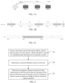
- Rel-18 WID supports a single DCI to schedule PDSCHs or PUSCHs of a plurality of cells. It should be noted that each cell corresponds to one PDSCH and one PUSCH. Scheduling the PDSCHs of three cells through one DCI may be shown in FIG. 1A , for example.
- the FDRA field is used to indicate the frequency domain resource of data transmission of the cell. It is proposed in the Rel-17 scenario design of single DCI scheduling two cell that the DCI FDRA field can be simply expanded, that is, the frequency domain information of scheduling data of two cells is indicated based on different bits.
- a single DCI can schedule three or more cells simultaneously. If the FDRA field is simply extended based on the above method, the number of bits occupied by the FDRA field will be significantly increased and the DCI bits overhead will be increased. For example, a single DCI schedules three cells and the number of RBs occupied by BWP configured for each cell is 100, if the FDRA field corresponding to the three cells is based on resource type 1, the number of bits occupied by the corresponding FDRA field is 39, which greatly increases the DCI overhead and reduces DCI transmission resources.
- RRC Radio Resource Control
- type 0 refers to indicating the resource block group (RBG) corresponding to transmission of the PDSCH or PUSCH within a range of the Bandwidth Part (BWP) through a bitmap.
- the RBG consists of P consecutive RBs.
- the size of P is related to the BWP size and RBG configuration.
- the BWP size may be determined by the number of RBs occupied by the BWP. For example, the corresponding relationship may be shown in Table 1.
- type 1 determines the frequency domain resources for the PDSCH or PUSCH transmission in the BWP by the start position plus the continuous length, and the frequency domain resources are continuously distributed in the frequency domain.
- the start RB index of the frequency domain resource for data transmission of the cell determined in type 1 is RB#7, and the continuous length is 9, then RB#7 to RB#15 can be used as the frequency domain resource for data transmission.
- the terminal can dynamically switch between the resource allocation type of type 0 and the resource allocation type of type 1 based on the indication of the Most Significant Bit (MSB) of the FDRA field.
- MSB Most Significant Bit
- the corresponding FDRA field is of the resource allocation type of type 0. If the MSB indication is 1, the corresponding FDRA field is of the resource allocation type of type 1.
- the length of the FDRA field in DCI is determined according to the resource allocation manner that occupies the longer FDRA field in the two resource allocation manners.
- the RB mentioned in the present disclosure may refer to a physical resource block (PRB), a virtual resource block (VRB), or a collective name for PRB and VRB, which is not limited in the present disclosure.
- the present disclosure provides a resource determination method and apparatus, a multi-carrier scheduling method and apparatus, and a storage medium.
- the DCI bit overhead is reduced, the problem of reduced DCI transmission efficiency is effectively avoided, and high availability is achieved.
- the resource determination method provided by the present disclosure is first introduced from the terminal side.
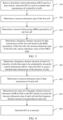
- FIG. 2 is a flowchart of a resource determination method according to an embodiment, the method may be executed by a terminal and the method may include the following steps.
- step 201 downlink control information (DCI) sent by a base station is received; where the DCI is used to schedule data transmission of a plurality of cells.
- DCI downlink control information
- the DCI for scheduling data transmission of a plurality of cells may include, but is not limited to, scheduling PDSCH of a plurality of cells and/or PUSCH of a plurality of cells. Each cell corresponds to one PDSCH and/or each cell corresponds to one PUSCH.
- step 202 a resource allocation type of a first cell is determined.
- the first cell may be any one of the plurality of cells.
- the resource allocation type of the first cell may be determined through the RRC signaling sent by the base station.
- the resource allocation type of the first cell may be type 0, type 1 or dynamic.
- a frequency domain resource for data transmission of the first cell is determined based on at least the resource allocation type of the first cell and an indication value of a frequency domain resource allocation (FDRA) field in the DCI.
- FDRA frequency domain resource allocation
- the DCI bit overhead can be reduced effectively, the problem of reduced DCI transmission efficiency can be efficiently avoided, and high availability can be achieved.
- the terminal may jointly determine the frequency domain resource for data transmission of the first cell based on the RBG granularity of the first cell, the resource allocation type of the first cell, and the indication value of the FDRA field.
- the first cell may be any one of the plurality of cells scheduled by DCI.
- the method may be executed by a terminal, and the method may include the following steps.
- step 301 downlink control information (DCI) sent by a base station is received; where the DCI is used to schedule data transmission of a plurality of cells.
- DCI downlink control information
- the DCI for scheduling data transmission of a plurality of cells may include, but is not limited to, scheduling PDSCH of a plurality of cells and/or PUSCH of a plurality of cells. Each cell corresponds to one PDSCH and/or each cell corresponds to one PUSCH.
- step 302 a resource allocation type of the first cell is determined.
- the first cell may be any one of the plurality of cells.
- the resource allocation type of the first cell may be determined through the RRC signaling sent by the base station.
- the resource allocation type of the first cell may be type 0, type 1 or dynamic.
- a resource block group (RBG) granularity of the first cell is determined.
- the RBG granularity P of the first cell can be determined according to the BWP size and a configuration identifier indicated by the RRC signaling sent by the base station.
- step 302 and step 303 is not limited.
- a frequency domain resource for data transmission of the first cell is determined based on the RBG granularity of the first cell, the resource allocation type of the first cell, and an indication value of the FDRA field.
- the frequency domain resource for data transmission of the first cell may be determined in combination with the RBG granularity of the first cell, the resource allocation type of the first cell and the indication value of the FDRA field.
- the DCI bit overhead is reduced, the problem of reduced DCI transmission efficiency is effectively avoided, and high availability is achieved.
- the RBG granularity of the first cell may be determined based on a first corresponding relationship among a first RB number range, candidate configuration identifiers, and candidate RBG granularities.
- the first RB number range is an RB number range to which the number of RBs occupied by the bandwidth part (BWP) configured for the first cell belongs.
- the first RB number range corresponds to three or more candidate configuration identifiers, and each of the candidate configuration identifiers corresponds to one of the candidate RBG granularities.
- the present disclosure can expand the corresponding relationship provided in Table 1, and at least add configuration of configuration 3, for example, as shown in Table 2.
- Table 2 BWP size Configuration 1 Configuration 2 Configuration 3 ... 1-36 2 4 P 31 ... 37-72 4 8 P 32 ... 73-144 8 16 P 33 ... 145-275 16 16 P 34 ...
- the candidate RBG granularity corresponding to configuration 3 may be greater than or equal to the candidate RBG granularity corresponding to configuration 2. That is, P 31 may be greater than or equal to 4, P 32 may be greater than or equal to 8, and so on. If Table 2 also includes configuration 4, the candidate RBG granularity corresponding to configuration 4 may be greater than or equal to the candidate RBG granularity corresponding to configuration 3.
- the terminal can determine the first RB number range based on the number of RBs occupied by the BWP configured for the first cell, and then jointly determine the RBG granularity P of the first cell based on the first RB number range and the candidate configuration identifier indicated by the base station via RRC signaling through the corresponding relationship in Table 2.
- the RBG granularities of a plurality of cells are the same. On this basis, the RBG granularity of the plurality of cells is determined based on the corresponding relationship among a second RB number range, the candidate configuration identifier, and the candidate RBG granularities.
- the second RB number range is an RB number range to which a sum or average of the numbers of RBs occupied by the BWPs configured for the plurality of cells belongs.
- the number of RBs occupied by the BWPs configured for three cells are 25, 37, and 76 respectively, and the average is 46. It is assumed that the average belongs to the RB number range 2 and the candidate configuration identifier is 1, based on the second corresponding relationship, it can be determined that the RBG granularities of the three cells are equal, and are all P 12 . It is assumed that the value of P 12 is 4, then the RBG granularities of these three cells are all 4.
- the second RB number range corresponds to three or more candidate configuration identifiers, and each of the candidate configuration identifiers is used to determine one of the candidate RBG granularities, as shown in Table 3.
- Table 3 Second RB number range Configuration 1 Configuration 2 Configuration 3 ... RB number range 1 P 11 P 21 P 31 ... RB number range 2 P 12 P 22 P 32 ... RB number range 3 P 13 P 23 P 33 ... RB number range 4 P 14 P 24 P 34 ...
- the second RB number range is the RB number range to which the sum or average of the numbers of RBs occupied by the BWPs configured for the plurality of cells belongs.
- the second RB number range is the RB number range to which the average of RBs occupied by the BWPs configured for a plurality of cells belongs, for example, the second RB number range (represented by the average BWP size) in Table 3 may be the same as the value range corresponding to BWP size in Table 2.
- the RBG granularities corresponding to configuration 1, configuration 2, configuration 3, etc. in Table 3 may also be the same as the RBG granularities corresponding to configuration 1, configuration 2, configuration 3, etc. in Table 2.
- the second RB number range corresponds to two or more candidate configuration identifiers, and each of the candidate configuration identifiers is used to determine one of the candidate RBG granularities, as shown in Table 4.
- Table 4 Second RB number range Configuration 1 Configuration 2 RB number range 1 P 11 P 21 RB number range 2 P 12 P 22 RB number range 3 P13 P23 RB number range 4 P14 P24
- the second RB number range is the RB number range to which the average of RBs occupied by the BWPs configured for a plurality of cells belongs, for example, the second RB number range (expressed by the average BWP size) in Table 4 may be the same as the value range corresponding to the BWP size in Table 2.
- the RBG granularities corresponding to configuration 1 and configuration 2 in Table 4 may also be the same as the RBG granularities corresponding to configuration 1 and configuration 2 in Table 2.
- the terminal may determine the RBG granularity P of the first cell based on the second RB number range and the candidate configuration identifier indicated by the base station through RRC signaling based on Table 3 or Table 4.
- any of the above methods may be used to determine the RBG granularity of the first cell, so that the frequency domain resource for data transmission of the first cell may be determined subsequently based on the RBG granularity of the first cell, the resource allocation type of the first cell and the indication value of the FDRA field. It is easy to be implemented and has high usability.
- the process of determining the frequency domain resource for data transmission of the first cell based on the RBG granularity of the first cell, the resource allocation type of the first cell and the indication value of the FDRA field includes the following steps.
- the terminal determines the RB range occupied by each RBG of the BWP configured for the first cell.
- N RBG N BWP , i size + N BWP , i strat mod P / P
- RBG#0 includes RB#0 to RB#3
- RBG#1 includes RB#4 to RB#7
- RBG#2 includes RB#8 to RB#11
- RBG#3 includes RB#12 to RB#15
- RBG#4 includes RB#16 to RB#19
- RBG#5 includes RB#20 to RB#23
- RBG# 6 only includes RB#24.
- the terminal determines the frequency domain resource for data transmission of the first cell based on the resource allocation type of the first cell and the indication value of the FDRA field.
- the FDRA field indicates the frequency domain resource for data transmission of the first cell in a bitmap manner, and the terminal can determine the RBG indexes for data transmission of the first cell based on the indication value of the FDRA field.
- the FDRA field can indicate the frequency domain resource of the first cell through the resource indication value (RIV), where RIV is associated with the start RBG index and the RBG continuous number for data transmission.
- RIV is associated with the start RBG index and the RBG continuous number for data transmission.
- the terminal can determine the start RBG index and the RBG continuous number for data transmission of the first cell based on the indication value of the FDRA field.
- the terminal can determine the resource allocation type of the first cell to be type0 or type1 based on the MSB of the FDRA field, and then determine the frequency domain resource for data transmission of the first cell in the above manner.
- the RBG granularity of the first cell may be determined based on the above-mentioned first corresponding relationship or second corresponding relationship.
- the first RB number range corresponds to three or more candidate configuration identifiers.
- the configuration identifier is large, the corresponding RBG granularity may be large, thereby increasing the number of RBs included in each RBG.
- the bits included in the FDRA field can be effectively reduced.
- the second RB number range of the RBG granularity is determined to be the RB number range to which the sum or average of the numbers of RBs occupied by the BWPs configured for the plurality of cells belongs, which can also reduce the number of bits included in the FDRA field.
- the DCI bit overhead is reduced, the problem of reduced DCI transmission efficiency is effectively avoided, and high availability is achieved.
- the resource allocation types of the plurality of cells scheduled by DCI may be limited to be the same.
- the FDRA field may indicate in the following manners.
- the FDRA field adopts the manner of joint indication.
- the resource allocation types of the plurality of cells are all of the first type, and the RBG indexes of data transmission of the plurality of cells may be determined based on a first reference cell.
- the first type indicates the frequency domain resource for data transmission of the cell through a bitmap, that is, the first type is type0.
- the first reference cell is a cell different from the first cell among the plurality of cells.
- the first reference cell may be indicated by the base station through signaling, or the first reference cell may be determined through a protocol.
- a cell that receives DCI among a plurality of cells may be used as the first reference cell.
- the cell with the largest number of RBs occupied by the BWP configured in a plurality of cells may be used as the first reference cell.
- the cell with the smallest number of RBs occupied by the BWP configured in a plurality of cells may be used as the first reference cell.
- the cell with the largest corresponding cell index number among the plurality of cells may be used as the first reference cell.
- the cell with the smallest corresponding cell index number among the plurality of cells may be used as the first reference cell.
- the FDRA field is used to indicate: the RBG index of data transmission of the first reference cell.
- the terminal may determine the frequency domain resource for data transmission of the first cell based on the resource allocation type of the first cell and the indication value of the frequency domain resource allocation (FDRA) field in the DCI.
- FDRA frequency domain resource allocation
- the terminal may determine that the RBG index of the first cell is the maximum RBG index value of the first cell.
- the bitmap indicated by the FDRA field is: 1001011, the length is 6, and the maximum length of the RBG bitmap of the first cell is 7. Then the terminal determines that the RBG index of data transmission of the first cell is the same as that of the reference cell, which are RBG#0, RBG#3, RBG#5, RBG#6.
- the bitmap indicated by the FDRA field is: 1001011, the length is 6, and the length of the RBG bitmap of the first cell is 5, specifically: 100101. Then, it is determined that the RBG index of data transmission of the first cell is RBG#0, RBG#3, RBG#5.
- the second type may refer to type 1, and the FDRA field may be used to indicate the RIV of the first reference cell.
- the RIV of the first cell may be determined based on the RIV of the first reference cell.
- the RIV of the first reference cell is less than or equal to the maximum RIV determined by the BWP configured for the first cell, then it is determined that the RIV of the first cell is equal to the RIV of the first reference cell.
- the start RBG index and the number of continuous RBGs for data transmission of the first cell may be determined.
- the terminal may determine the start RBG index and the number of continuous RBGs for data transmission in the first cell according to the RIV of the first cell in accordance with the related art.
- the resource allocation types of a plurality of cells are a third type, that is, dynamic type.
- the terminal may first determine that the resource allocation type is type 0 or type 1 based on the MSB of the FDRA field, and then further determine the frequency domain resource for data transmission of the first cell in the above manner.
- the FDRA field adopts the manner of separate indications.
- the DCI may include a plurality of FDRA fields, and the number of the plurality of FDRA fields is equal to the number of cells of the plurality of cells.
- the DCI may include n FDRA fields, where n is a positive integer greater than 1.
- the resource allocation types of a plurality of cells are all the first type.
- the first type indicates the frequency domain resource for data transmission of the cell through a bitmap. That is, the first type is type0.
- the i-th FDRA field in the DCI is used to indicate: an RBG index of data transmission of the i-th scheduled cell among the plurality of cells, where i is a positive integer less than or equal to the number of cells.
- the terminal may determine the FDRA field corresponding to the first cell in the DCI, and determine the RBG index for data transmission of the first cell based on the indication value of the FDRA field corresponding to the first cell. It should be noted that the RBG index indicated by each FDRA field may be one or more, which is not limited by the present disclosure.
- the resource allocation types of a plurality of cells are all type 0, and the i -th FDRA field in the DCI is used to indicate: the RBG index of data transmission of the i -th scheduled cell among the plurality of cells, where i is a positive integer less than or equal to the number of cells.
- the designated bit in each FDRA field is used to indicate a set to which the available RBG index value for data transmission of the cell belongs.
- the available RBG index value for data transmission of the cell can only be an odd number or an even number.
- the terminal can determine whether the available RBG index value for data transmission of the corresponding scheduled cell is an odd number or an even number through the designated bit of each FDRA field.
- the terminal determines that the available RBG index value for data transmission of the first cell is an odd number; if the bit value of the designated bit in the FDRA field corresponding to the first cell is 0, the terminal determines that the available RBG index value for data transmission of the first cell is an even number, and vice versa.
- the bit value of the FDRA field is further reduced.
- the designated bit is the MSB, that is, the MSB of each FDRA field in the DCI is used to indicate whether the available RBG index value for data transmission of the cell is an even number or an odd number.
- the terminal determines that the resource allocation type of the first cell is type0 based on the MSB in the FDRA field corresponding to the first cell.
- the designated bit may be a bit located after the MSB and adjacent to the MSB, or the designated bit may be the least significant bit (LSB).
- the resource allocation types of a plurality of cells are all the second type, that is, type 1, and the i-th FDRA field in the DCI is used to indicate: the RIV of data transmission of the i-th scheduled cell among the plurality of cells, where i is a positive integer less than or equal to the number of cells.
- the terminal may determine the FDRA field corresponding to the first cell in the DCI, and determine the RIV of the first cell based on the indication value of the FDRA field corresponding to the first cell, thereby determining the start RBG index and the number of continuous RBGs for data transmission of the first cell.
- the resource allocation types of a plurality of cells are the third type, that is, dynamic.
- the MSB of the FDRA field of the DCI is used to indicate that the resource allocation types of the plurality of cells are all type0 or type1.
- the terminal After determining the resource allocation types of a plurality of cells, the terminal determines the frequency domain resource for data transmission of the first cell in the above manner.
- the resource allocation types of the plurality of cells can be limited to be the same, and then the frequency domain resource for data transmission of the first cell is determined in the above manner.
- the DCI bit overhead is reduced, the problem of reduced DCI transmission efficiency is effectively avoided, and high availability is achieved.
- the resource allocation types of the plurality of scheduled cells may not be limited to the same.
- the FDRA field may adopt a manner of partial joint indication.
- the FDRA field includes a plurality of bit intervals, and the number of the plurality of bit intervals is equal to the number of resource allocation types.
- the number of the resource allocation types is m
- the number of the bit intervals is also m.
- the number of resource allocation types is 4, including type0, type1, dynamic+type0, and dynamic+type1.
- dynamic+type0 means that the base station indicates that the resource allocation type of the cell is dynamic through RRC signaling, and further indicates that the resource allocation type of the cell is type0 through the MSB in the FDRA field.
- dynamic+type1 means that the base station indicates that the resource allocation type of the cell is dynamic through RRC signaling, and further indicates that the resource allocation type of the cell is type1 through the MSB in the FDRA field.
- the j -th bit interval of DCI is used to indicate: the frequency domain resource for data transmission of the cell corresponding to the j -th resource allocation type, where j is a positive integer less than or equal to the number of the resource allocation types.
- the terminal may determine a first bit interval of the FDRA field corresponding to the first cell based on the resource allocation type of the first cell. Further, based on the indication value of the first bit interval, the frequency domain resource for data transmission of the first cell is determined.
- the first bit interval is also used to indicate the frequency domain resource for data transmission of a second reference cell, and the frequency domain resource for data transmission of the first cell is determined based on the second reference cell.
- the second reference cell is a cell different from the first cell among cells whose resource allocation types are the same as the resource allocation type corresponding to the first bit interval.
- the manner in which the terminal determines the frequency domain resource for data transmission of the first cell is the same as the above-mentioned manner in which the FDRA field is used to indicate the frequency domain resource for data transmission of the reference cell and the terminal determines the frequency domain resource of the first cell based on the frequency domain resource corresponding to the reference cell, which is not elaborated here.
- the DCI bit overhead can also be reduced, the problem of reduced DCI transmission efficiency can be effectively avoided, and high availability can be achieved.
- the multi-carrier scheduling method provided by the present disclosure will be introduced from the base station side.
- An embodiment of the present disclosure provides a multi-carrier scheduling method.
- FIG. 4 is a flowchart of a multi-carrier scheduling method according to an embodiment, the method can be executed by a base station, and the method can include the following steps.
- step 401 a frequency domain resource of each of a plurality of cells that need to be scheduled by downlink control information (DCI) is determined; where the DCI is used to schedule data transmission of the plurality of cells.
- DCI downlink control information
- DCI for scheduling data transmission of a plurality of cells may include, but is not limited to, scheduling PDSCH of a plurality of cells and/or PUSCH of a plurality of cells. Each cell corresponds to one PDSCH and/or each cell corresponds to one PUSCH.
- step 402 a resource allocation type of data transmission of each cell is determined.
- the resource allocation type of each cell can be determined through RRC signaling sent by the base station, and the resource allocation type of the first cell can be type 0, type 1 or dynamic.
- a bit value of a frequency domain resource allocation (FDRA) field in the DCI is determined based on at least the resource allocation type of each cell and the frequency domain resource corresponding to each cell.
- FDRA frequency domain resource allocation
- the DCI bit overhead can be reduced, the problem of reduced DCI transmission efficiency can be effectively avoided, and high availability can be achieved.
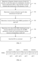
- FIG. 5 is a flowchart of a multi-carrier scheduling method according to an embodiment
- the method can be executed by a base station, and the method can include the following steps.
- step 501 a frequency domain resource of each of a plurality of cells that need to be scheduled by downlink control information (DCI) is determined; where the DCI is used to schedule data transmission of the plurality of cells.
- DCI downlink control information
- DCI used to schedule data transmission of a plurality of cells may include, but is not limited to, scheduling PDSCH of a plurality of cells and/or PUSCH of a plurality of cells. Each cell corresponds to one PDSCH and/or each cell corresponds to one PUSCH.
- step 502 a resource allocation type for data transmission of each cell is determined.
- the resource allocation type of each cell can be determined through RRC signaling sent by the base station, and the resource allocation type of the first cell can be type 0, type 1 or dynamic.
- step 503 a resource block group (RBG) granularity of each cell is determined.
- RBG resource block group
- the RBG granularity P of each cell can be determined according to a BWP size and a configuration identifier indicated by the RRC signaling sent by the base station.
- step 502 and step 503 is not limited.
- a bit value of the FDRA field is determined based on the resource allocation type of each cell, the RBG granularity of each cell, and the frequency domain resource corresponding to each cell.
- step 505 the DCI is sent to the terminal.
- the bit value of the FDRA field may be determined by combining the resource allocation type of each cell, the RBG granularity of each cell, and the frequency domain resource corresponding to each cell.
- the RBG granularity of the first cell may be determined based on a first corresponding relationship among a first RB number range, candidate configuration identifiers, and candidate RBG granularities.
- the first cell is any one of a plurality of cells.
- the first RB number range is an RB number range to which the number of RBs occupied by the bandwidth part (BWP) configured for the first cell belongs.
- the first RB number range corresponds to three or more candidate configuration identifiers, and each of the candidate configuration identifiers corresponds to one of the candidate RBG granularities.
- the present disclosure can extend the corresponding relationship provided in Table 1, and at least add configuration of configuration 3, for example, as shown in Table 2 above.
- the terminal can determine the first RB number range based on the number of RBs occupied by the BWP configured for the first cell, and then jointly determine the RBG granularity P of the first cell according to the first RB number range and the candidate configuration identifier indicated by the base station via RRC signaling through the corresponding relationship in Table 2.
- the RBG granularities of a plurality of cells are the same. On this basis, the RBG granularities of the plurality of cells are determined based on a second corresponding relationship among a second RB number range, the candidate configuration identifier, and the candidate RBG granularities.
- the second RB number range is an RB number range to which the sum or average of the numbers of RBs occupied by the BWPs configured for the plurality of cells belongs.
- the number of RBs occupied by the BWPs configured for three cells are 25, 37, and 76 respectively, and the average is 46. It is assumed that they belong to the RB number range 2, and the candidate configuration identifier is 1, based on the second corresponding relationship, it may be determined that the RBG granularities of the three cells are equal and are all P 12 . It is assumed that the value of P 12 is 4, then the RBG granularities of these three cells are all 4.
- the second RB number range corresponds to three or more candidate configuration identifiers, and each of the candidate configuration identifiers is used to determine one of the candidate RBG granularities, such as shown in Table 3 above.
- the second RB number range is the RB number range to which the average of RBs occupied by the BWPs configured for a plurality of cells belongs, for example, the second RB number range (represented by the average BWP size) in Table 3 may be the same as the value range corresponding to the BWP size in Table 2.
- the RBG granularities corresponding to configuration 1, configuration 2, configuration 3, etc. in Table 3 may also be the same as the RBG granularities corresponding to configuration 1, configuration 2, configuration 3, etc. in Table 2.
- the second RB number range corresponds to two or more candidate configuration identifiers, and each of the candidate configuration identifiers is used to determine one of the candidate RBG granularities, such as shown in Table 4 above.
- the terminal may determine the RBG granularity P of the first cell based on the second RB number range and the candidate configuration identifier indicated by the base station through RRC signaling and based on the above Table 3 or Table 4.
- the second RB number range is the RB number range to which the average of the numbers of RBs occupied by the BWPs configured for a plurality of cells belongs, for example, the second RB number range (expressed by the average BWP size) in Table 4 may be the same as the value range corresponding to the BWP size in Table 2.
- the RBG granularities corresponding to configuration 1 and configuration 2 in Table 4 may also be the same as the RBG granularities corresponding to configuration 1 and configuration 2 in Table 2.
- any of the above manners can be used to determine the RBG granularity of the first cell, so that the bit value of the FDRA field can be jointly determined subsequently based on the RBG granularity of the first cell, the resource allocation type of the first cell, and the frequency domain resource for data transmission of the first cell, which is easy to implement and has high availability.
- the base station may determine the bit value of the FDRA field based on the RBG granularity of the first cell, the resource allocation type of the first cell, and the frequency domain resource for data transmission of the first cell, At this time, the base station can expand the FDRA field in the DCI to indicate the frequency domain resource corresponding to each cell respectively.
- the bit value of this bit interval can be jointly determined based on the RBG granularity of the first cell and the RBG index of data transmission of the first cell.
- N RBG N BWP , i size + N BWP , i strat mod P / P .
- the bit interval corresponding to the first cell in the FDRA field can determine the RIV of the first cell based on the RBG granularity of the first cell, the start RBG index value of data transmission of the first cell, and the number of continuous RBGs, and then determine the bit value of the bit interval based on the RIV of the first cell.
- the base station can indicate that the resource allocation type of the first cell is type 0 or type 1 through the MSB in the FDRA field according to the dynamically determined resource allocation type of the first cell, and the bit values of the other bits can be determined in the above manner and will not be described again here.
- the base station may determine the bit value of the FDRA field based on the RBG granularity of the first cell, the resource allocation type of the first cell, and the frequency domain resource of data transmission of the first cell.
- the RBG granularity of the first cell may be determined based on the first corresponding relationship or the second corresponding relationship.
- the resource allocation types of the plurality of cells scheduled by DCI may be limited to be the same.
- the FDRA field can be indicated in the following manners:
- the FDRA field adopts a manner of joint indication.
- the resource allocation types of the plurality of cells are all the first type, and the RBG indexes of data transmission of the plurality of cells may be determined based on a first reference cell.
- the first type indicates the frequency domain resource for data transmission of the cell through a bitmap, that is, the first type is type0.
- the first reference cell is a cell different from the first cell among the plurality of cells.
- the first reference cell may be indicated by the base station through signaling, or the first reference cell may be determined through a protocol.
- a cell that receives DCI among a plurality of cells may be used as the first reference cell.
- the cell with the largest number of RBs occupied by the BWP configured in a plurality of cells may be used as the first reference cell.
- the cell with the smallest number of RBs occupied by the BWP configured in a plurality of cells may be used as the first reference cell.
- the cell with the largest corresponding cell index number among the plurality of cells may be used as the first reference cell.
- the cell with the smallest corresponding cell index number among the plurality of cells may be used as the first reference cell.
- the FDRA field is used to indicate: the RBG index of data transmission of the first reference cell.
- the base station determines the frequency domain resource for data transmission of the first cell based on the resource allocation type of the first cell and the RBG index of data transmission of the first reference cell.
- the terminal may determine that the RBG index of the data transmission of the first cell is the same as the first reference cell.
- the terminal may determine that the RBG index of the first cell is the maximum RBG index value of the first cell. At this time, the terminal may determine the bit value of the frequency domain resource allocation (FDRA) field in the DCI based on the RBG index of the data transmission of the first reference cell.
- FDRA frequency domain resource allocation
- the resource allocation types of the plurality of cells are the second type, and the frequency domain resource for data transmission of the plurality of cells may be determined based on the first reference cell.
- the second type may refer to type 1, and the FDRA field may be used to indicate the RIV of the first reference cell.
- the RIV of the first cell may be determined based on the RIV of the first reference cell.
- the RIV of the first reference cell is less than or equal to the maximum RIV determined by the BWP configured for the first cell, then it is determined that the RIV of the first cell is equal to the RIV of the first reference cell.
- the start RBG index and the number of continuous RBGs for data transmission of the first cell may be determined.
- the RIV of the first reference cell is greater than the maximum RIV determined by the BWP configured for the first cell, it may be determined that the RIV of the first cell is equal to a preset RIV.
- the preset RIV may be the maximum RIV of the first cell.
- the terminal may determine the bit value of the frequency domain resource allocation (FDRA) field in the DCI based on the RIV of the first reference cell.
- FDRA frequency domain resource allocation
- the resource allocation types of a plurality of cells are a third type, that is, dynamic type.
- the terminal may first determine that the resource allocation type is type0 or type1 based on the MSB of the FDRA field, and then determine the bit value of the FDRA field in the above manner.
- the FDRA field adopts a manner of separate indications.
- the DCI may include a plurality of FDRA fields, and the number of the plurality of FDRA fields is equal to the number of cells of the plurality of cells.
- the resource allocation types of a plurality of cells are all the first type.
- the first type indicates the frequency domain resource of data transmission of the cell through a bitmap, that is, the first type is type0, and the i-th FDRA field in the DCI is used to indicate: the RBG index of data transmission of the i-th scheduled cell among the plurality of cells, where i is a positive integer less than or equal to the number of cells.
- the base station may determine the bit value of the i-th FDRA field in the DCI based on the RBG index of the data transmission of the i-th scheduled cell among the plurality of cells. It should be noted that the RBG index indicated by each FDRA field may be one or more, which is not limited by the present disclosure.
- the resource allocation types of a plurality of cells are all type 0, and the i-th FDRA field in the DCI is used to indicate: the RBG index of data transmission of the i-th scheduled cell among the plurality of cells, where i is a positive integer less than or equal to the number of cells.
- the designated bit in each FDRA field is used to indicate a set to which the available RBG index values for data transmission of the cell belong.
- the set to which available RBG index values for data transmission in the cell belong can only be an odd number, or can only be an even number.
- the base station determines the bit value of the designated bit of each FDRA field based on whether the available RBG index value for data transmission of the scheduled cell is an odd number or an even number.
- the base station determines that the available RBG index value for data transmission of the first cell is an odd number, the base station determines that the bit value of the designated bit in the FDRA field corresponding to the first cell is 1; if the available RBG index value for data transmission of the first cell is an even number, the base station determines that the bit value of the designated bit in the FDRA field corresponding to the first cell is 0, and vice versa.
- the bit value of the FDRA field is further reduced.
- the designated bit is the MSB, that is, the MSB of each FDRA field in the DCI is used to indicate whether the available RBG index value for data transmission of the cell is an even number or an odd number.
- the base station determines the MSB in the FDRA field according to the resource allocation type of the first cell being type0, at this time, the MSB is occupied, and the designated bit may be one bit located after the MSB and adjacent to the MSB, or the designated bit may be the least significant bit (LSB).
- the resource allocation types of a plurality of cells are all the second type, that is, type 1, and the i-th FDRA field in the DCI is used to indicate: the RIV of data transmission of the i-th scheduled cell among the plurality of cells, where i is a positive integer less than or equal to the number of cells.
- the base station may determine the FDRA field corresponding to the first cell in the DCI, and determine the bit value of the FDRA field corresponding to the first cell based on the RIV of the first cell.
- the resource allocation types of a plurality of cells are the third type, that is, dynamic.
- the MSB of the FDRA field of the DCI is used to indicate that the resource allocation types of a plurality of cells are type0 or type1.
- the bit value(s) of other bit(s) is determined in a manner similar to the above manner and will not be described again here.
- the resource allocation types of a plurality of cells may be defined to be the same, and then the bit value of the FDRA field is determined in the above manner.
- the DCI bit overhead is reduced, the problem of reduced DCI transmission efficiency is effectively avoided, and high availability is achieved.
- the resource allocation types of the plurality of scheduled cells may not be defined to the same.
- the FDRA field may adopt a manner of partial joint indication.
- the FDRA field includes a plurality of bit intervals, and the number of the plurality of bit intervals is equal to the number of the resource allocation types.
- the number of bit intervals is also m.
- the number of the resource allocation types is 4, including type0, type1, dynamic+type0, and dynamic+type1.
- dynamic+type0 means that the base station indicates that the resource allocation type of the cell is dynamic through RRC signaling, and further indicates that the resource allocation type of the cell is type0 through the MSB in the FDRA field.
- dynamic+type1 means that the base station indicates that the resource allocation type of the cell is dynamic through RRC signaling, and further indicates that the resource allocation type of the cell is type1 through the MSB in the FDRA field.
- the j -th bit interval of DCI is used to indicate: the frequency domain resource for data transmission of the cell corresponding to the j -th resource allocation type, where j is a positive integer less than or equal to the number of the resource allocation types.
- the base station may determine the resource allocation type of the first cell, and then determine the first bit interval of the FDRA field corresponding to the first cell.
- the bit value of the first bit interval is determined according to the frequency domain resource for data transmission of the first cell.
- the first bit interval is also used to indicate the frequency domain resource for data transmission of a second reference cell, and the frequency domain resource for data transmission of the first cell is determined based on the second reference cell.
- the second reference cell is a cell different from the first cell among cells whose resource allocation types are the same as the resource allocation type corresponding to the first bit interval.
- the DCI bit overhead can also be reduced on the basis of ensuring the flexibility of DCI scheduling, the problem of reduced DCI transmission efficiency can be effectively avoided, and high availability can be achieved.
- the terminal is a Rel-18 and subsequent version terminal, and the terminal receives DCI for multi-cell scheduling, based on the indication information corresponding to the DCI, PDSCHs of a plurality of cells are received or PUSCHs of a plurality of cells are transmitted.
- the frequency domain resource information of different scheduled cells indicated by the FDRA field of the DCI (multi-cell DCI, mc DCI) for scheduling a plurality of cells is based on type 0, type 1 or dynamic resource allocation manner, by defining the number of RBs contained in the RBG corresponding to mc DCI to be P, the mc DCI is enabled to indicate the frequency domain resource information of PDSCHs or PUSCHs of a plurality of scheduled cells. It is worth noting that based on RBG, mc DCI can implement scheduling of FDRA field through type 0 and type 1 with RBG as the granularity.
- the RBGs corresponding to different scheduled cells are not exactly the same.
- the configuration of configuration 3 is added.
- the RBG granularity P corresponding to configuration 3 is greater than or equal to the granularity corresponding to configuration 2.
- the terminal determines P based on the BWP size configured for the scheduled cell i and a configuration option indicated by signaling.
- the configuration option is indicated by the configuration signaling of the scheduled cell i, such as RRC signaling, and the configuration can also be configured by the cell where mc DCI is received.
- Table 5 table 5 BWP size Configuration 1 Configuration 2 Configuration 3 1-36 2 4 8 37-72 4 8 16 73-144 8 16 32(16) 145-275 16 16 32(16)
- the number of RBs occupied by the corresponding mc DCI RBG may be equal to 32 or 16.
- the RBG granularities corresponding to different scheduled cells are the same, for example, they are all P.
- P corresponds to the BWP sizes and configurations configured for all scheduled cells simultaneously scheduled by mc DCI.
- Table 6 BWP size average Configuration 1 Configuration 2 Configuration 3 1-36 2 4 8 37-72 4 8 16 73-144 8 16 32(16) 145-275 16 16 32(16)
- the BWP size described in Table 6 is equal to the average of the BWP sizes configured for all scheduled cells scheduled by mc DCI simultaneously. In another possible implementation, it is also possible to define that the sum of the BWP sizes configured for all scheduled cells scheduled by mc DCI simultaneously is associated with P. The specific implementation is similar to Table 6, which is not elaborated in the present disclosure.
- configuration 3 is added.
- the configuration options are configured by the cell where the mc DCI is received.
- the configuration options can also be configured separately through each scheduled cell, e.g., configured by RRC signaling. In this scenario, it is necessary to limit the configuration options of respective cells that are scheduled simultaneously to be the same. If the configurations of respective scheduled cells are different, the terminal determines the RBG granularity based on the configuration configured for the cell where the MC DCI is received and Table 6, or the terminal determines this as an error case and no longer processes it.
- the number of RBs occupied by the corresponding mc DCI RBG may be equal to 32 or 16.
- the RBG granularities corresponding to different scheduled cells are the same, for example, they are all P.
- P corresponds to the BWP sizes and configurations configured for all scheduled cells simultaneously scheduled by mc DCI.
- Table 7 BWP size average Configuration 1 Configuration 2 1-36 2 4 37-72 4 8 73-144 8 16 145-275 16 16
- the BWP size described in Table 7 is equal to the average of BWP sizes configured for all scheduled cells scheduled by mc DCI simultaneously. In another possible implementation, it is also possible to define that the sum of the BWP sizes configured for all scheduled cells scheduled by mc DCI simultaneously is associated with P. The specific implementation is associated with Table 1, which is not elaborated in the present disclosure.
- the described configuration 1 and configuration 2 are based on the basis defined in Table 1.
- the configuration options are configured by the cell where the mc DCI is received.
- the configuration options may also be configured separately through each scheduled cell, for example, configured by RRC signaling. In this scenario, it is necessary to restrict the configuration options of respective cells that are scheduled simultaneously to be the same. If the configurations of respective scheduled cells are different, the terminal determines the RBG granularity based on the configuration configured for the cell where the mc DCI is received and Table 7, or the terminal determines this as an error case and no longer processes it.
- N RBG N BWP , i size + N BWP , i strat mod P / P
- the terminal may determine the frequency domain information for data transmission of the scheduled cell i based on the FDRA resource configuration type and mc DCI FDRA field indication information. If the terminal is based on the resource allocation type of type 1, and the frequency domain resource allocation uses RBG as the granularity, the corresponding relationship between the RIV indicated by the FDRA field and the corresponding frequency domain information is the same as the DCI format 1_2 of the existing mechanism, which will not be elaborated in the present disclosure.
- whether the corresponding frequency domain resource allocation is based on the granularity of RB or the granularity of RBG can be determined based on a predefined manner. For example, if the number of cells scheduled simultaneously is less than or equal to n, the corresponding frequency domain resource allocation is based on the granularity of RB; if the number of cells scheduled simultaneously is greater than n , the corresponding frequency domain resource allocation is based on the granularity of RB; n may be determined by predefinition or signaling indication.
- whether the corresponding frequency domain resource allocation is based on the granularity of RB or the granularity of RBG may also be determined based on signaling indication. For example, 1 bit is added to the FDRA field to indicate whether the granularity is RB or RBG.
- the above information is indicated in the MSB of the mc DCI FDRA field, the MSB bit value of 0 corresponds to using RB as the granularity, and the MSB bit value of 1 corresponds to using RBG as the granularity, and vice versa.
- the design rule of this embodiment defines the RBG granularity in mc scenarios, which can effectively reduce FDRA signaling overhead, achieve consistent understanding of RBG granularity between the base station and the terminal, and improve the scheduling efficiency of MC DCI.
- the terminal is a Rel-18 and subsequent version terminal, and the terminal receives DCI for multi-cell scheduling. Based on the indication information corresponding to the DCI, it receives PDSCHs of a plurality of cells or transmits PUSCHs of a plurality of cells.
- This embodiment considers that the frequency domain resource information of different scheduled cells indicated by the FDRA field of multi-cell DCI may be based on type 0, type 1 and dynamic resource type scenarios, and by designing the corresponding FDRA field indication manner, scheduling of PDSCH/PUSCH of a plurality of cells by a single DCI can be achieved.
- a possible implementation is to determine a first reference cell in the mc scheduling scenario.
- the first reference cell can be determined based on a signaling indication, for example, indicating the cell index value of the first reference cell.
- the reference cell can also be determined in a predefined manner. For example, the cell where mc DCI is received is the first reference cell, or among all cells scheduled simultaneously by mc DCI, the cell corresponding to the largest (smallest) number of RBs occupied by the configured BWP is the first reference cell, or, among all cells scheduled simultaneously by mc DCI, the cell corresponding to the smallest (largest) cell id is the first reference cell, which is not limited by the present disclosure.
- One possible implementation is that for a plurality of cells scheduled by the same mc DCI, in order to reduce the DCI overhead of the mc FDRA field, and at the same time, in order to reduce the processing complexity of the terminal, the resource allocation types of the plurality of cells are restricted to be the same.
- the frequency domain resources corresponding to different cells are determined based on the first reference cell.
- the mc DCI FDRA field indicates the RIV (type 1) or RBG bitmap (type 0) of the reference cell. For other scheduled cells, if the indicated RIV (type 1) or RBG bitmap (type 0) is less than or equal to the maximum RIV value or the longest RBG bitmap (type 0) determined based on the number of BWPs configured for the current cell, the RIV (type 1) or RBG bitmap (type 0) corresponding to FDRA of other scheduled cells is the same as the reference cell; otherwise, the RIV (type 1) or RBG bitmap (type 0) corresponding to the FDRA of other scheduled cells is equal to the maximum RIV value or the longest RBG bitmap (type 0) determined based on the number of BWPs configured for the current cell.
- the MSB of the mc DCI FDRA field indicates one of the resource allocation manners of type 0 or type 1 for all scheduled cells.
- the set to which the corresponding available RBG index value belongs is an odd set or an even set.
- the MSB of the mc DCI FDRA field indicates that the set to which the available RBG index value belongs is an odd set or an even set.
- the terminal is based on the resource allocation type of dynamic, and the MSB of the mc DCI FDRA field indicates that the resource allocation manner of all scheduled cells is type 0, then one bit after the MSB of the mc DCI FDRA field (or LSB) indicates whether the set to which the available RBG index values belong is an odd set or an even set. If the terminal is based on the resource allocation type of dynamic, and the MSB of the mc DCI FDRA field indicates that the resource allocation manner of all scheduled cells is type 1, then one bit after the MSB of the mc DCI FDRA field (or LSB) indicates that the granularity is one of RB and RBG.
- This embodiment limits the resource allocation types corresponding to the FDRA field of different scheduled cells in the mc scheduling scenario to be the same, which can effectively reduce the multi-cell DCI bits overhead, and avoid the multi-cell DCI transmission code rate being too high to lose the DCI transmission performance and reduce the scheduling performance of the cell.
- the terminal is a Rel-18 and subsequent version terminal, and the terminal receives DCI for multi-cell scheduling. Based on the indication information corresponding to the DCI, it receives PDSCHs of a plurality of cells or transmits PUSCHs of a plurality of cells.
- This embodiment considers that the frequency domain resource information of different scheduled cells indicated by the FDRA field of multi-cell DCI may be based on the resource types of type0, type 1 and dynamic, and does not limit the frequency domain resource types of different scheduled cells to be the same.
- a single DCI can be used to schedule PDSCH/PUSCH of multi-cell.
- the FDRA field corresponding to mc DCI is composed of different bit intervals.
- the number of bit intervals is equal to 1, 2 or 3.
- the number of bit intervals is determined by the type of resource allocation type (type 0, type 1, dynamic) corresponding to the FDRA configured by all scheduled cells scheduled by mc DCI simultaneously.
- the resource allocation types corresponding to FDRA of different scheduled cells are configured by RRC signaling.
- the bit intervals correspond to different resource allocation types one by one.
- the corresponding bit intervals can correspond according to the order of resource allocation manner type 0, type 1, and dynamic one by one.
- the same bit interval indicates the frequency domain resource of one or more scheduled cells corresponding to the same resource allocation manner.
- the frequency domain resources of one or more scheduled cells corresponding to the same resource allocation manner are indicated through joint indication.
- the number of bits occupied by the bit interval corresponding to type 0 or type 1 is determined by the resource allocation type and the configured BWP of the reference cell.
- the specific indication manner is as follows.
- the bit corresponding to the specific bit interval indicates the RIV or RBG of a second reference cell.
- the frequency domain resources of other cells using the same resource allocation manner are determined based on the second reference cell.
- the specific determination manner is similar to the second embodiment, which is not elaborated in the present disclosure.
- the cell corresponding to the largest (smallest) number of RBs occupied by the configured BWP among one or more cells corresponding to the same resource allocation manner may be the second reference cell, or the cell corresponding to the smallest (largest) cell id among one or more cells corresponding to the same resource allocation manner and scheduled simultaneously by mc DCI is the second reference cell, which is not limited in the present disclosure.
- the frequency domain resources of one or more scheduled cells corresponding to the resource allocation manner of dynamic are indicated in a separate manner.
- the bit interval corresponding to dynamic corresponds to the frequency domain resources of one or more scheduled cells corresponding to the resource allocation manner of dynamic one by one.
- the one or more scheduled cells correspond one by one based on the order of cell index values from small to large or from large to small.
- this embodiment designs a manner of partial joint indication, which can effectively reduce the multi-cell DCI bits overhead and avoid multi-cell DCI transmission code rate to be too high to lose DCI transmission performance and reduce cell scheduling performance.
- the present disclosure also provides an application function implementation apparatus embodiment.
- FIG. 7A is a block diagram of a resource determination apparatus according to an exemplary embodiment, the apparatus is applied to a terminal and includes:
- FIG. 7B which is a block diagram of a resource determination apparatus according to an exemplary embodiment, the apparatus is applied to a terminal and includes:
- FIG. 7C is a block diagram of a resource determination apparatus according to an exemplary embodiment, the apparatus is applied to a terminal and includes:
- FIG. 8A is a block diagram of a multi-carrier scheduling apparatus according to an exemplary embodiment, the apparatus is applied to a base station and includes:
- FIG. 8B is a block diagram of a multi-carrier scheduling apparatus according to an exemplary embodiment, the apparatus is applied to a base station and includes:
- FIG. 8C is a block diagram of a multi-carrier scheduling apparatus according to an exemplary embodiment, the apparatus is applied to a base station and includes:
- the partial description of the method embodiments may be referred to.
- the apparatus embodiments described above are only illustrative.
- the units described above as separate components may or may not be physically separated.
- the components shown as units may or may not be physical units, that is, they may be located in a place, or may be distributed to a plurality of network units. Some or all of the modules can be selected according to actual needs to achieve the purpose of the solutions of the present disclosure. Persons of ordinary skill in the art can understand and implement them without any creative effort.
- the present disclosure also provides a computer-readable storage medium that stores a computer program, and the computer program is used to execute any one of the above resource determination methods.
- the present disclosure also provides a computer-readable storage medium that stores a computer program, and the computer program is used to execute any one of the above multi-carrier scheduling methods.
- the present disclosure also provides a resource determination apparatus, including:
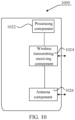
- FIG. 9 is a block diagram of a resource determining apparatus 900 according to an exemplary embodiment.
- the apparatus 900 may be a mobile phone, a tablet, an e-book reader, a multimedia playback device, a wearable device, a vehicle-mounted user equipment, an iPad, a smart TV, and other terminals.
- the apparatus 900 may include one or more of the following components: a processing component 902, a memory 904, a power component 906, a multimedia component 908, an audio component 910, an input/output (I/O) interface 912, a sensor component 916, and a communication component 918.
- the processing component 902 typically controls overall operations of the apparatus 900, such as the operations associated with display, telephone calls, data random access, camera operations, and recording operations.
- the processing component 902 may include one or more processors 920 to execute instructions to perform all or part of the steps of the above-described resource determination method.
- the processing component 902 may include one or more modules which facilitate the interaction between the processing component 902 and other components.
- the processing component 902 may include a multimedia module to facilitate the interaction between the multimedia component 908 and the processing component 902.
- the processing component 902 may read executable instructions from the memory to implement the steps of the resource determination method provided by the above embodiments.
- the memory 904 is configured to store various types of data to support the operations of the apparatus 900. Examples of such data include instructions for any applications or methods operating on the apparatus 900, contact data, phonebook data, messages, pictures, videos, etc.
- the memory 904 may be implemented using any type of volatile or non-volatile memory devices, or a combination thereof, such as a static random access memory (SRAM), an electrically erasable programmable read-only memory (EEPROM), an erasable programmable read-only memory (EEPROM), a programmable read-only memory (EPROM), a programmable read-only memory (PROM), a read-only memory (ROM), a magnetic memory, a flash memory, a magnetic or optical disk.
- SRAM static random access memory
- EEPROM electrically erasable programmable read-only memory
- EEPROM erasable programmable read-only memory
- EPROM programmable read-only memory
- PROM programmable read-only memory
- ROM read-only memory
- the power supply component 906 provides power to various components of the apparatus 900.
- the power supply component 906 may include a power management system, one or more power sources, and other components associated with the generation, management, and distribution of power in the apparatus 900.
- the multimedia component 908 includes a display screen providing an output interface between the apparatus 900 and the user.
- multimedia component 908 includes a front camera and/or a rear camera.
- the front camera and/or the rear camera may receive an external multimedia datum while the apparatus 900 is in an operation mode, such as a shooting mode or a video mode.
- Each of the front camera and the rear camera may be a fixed optical lens system or have focus and optical zoom capability.
- the audio component 910 is configured to output and/or input audio signals.
- the audio component 910 includes a microphone (MIC) configured to receive an external audio signal when the apparatus 900 is in an operation mode, such as a call mode, a recording mode, and a voice recognition mode.
- the received audio signal may be further stored in the memory 904 or transmitted via the communication component 918.
- the audio component 910 further includes a speaker to output audio signals.
- the I/O interface 912 provides an interface between the processing component 902 and peripheral interface modules, such as a keyboard, a click wheel, buttons, and the like.
- the buttons may include, but are not limited to, a home button, a volume button, a starting button, and a locking button.
- the sensor component 916 includes one or more sensors to provide status assessments of various aspects of the apparatus 900. For instance, the sensor component 916 may detect an open/closed status of the apparatus 900, relative positioning of components, e.g., the display and the keypad, of the apparatus 900, a change in position of the apparatus 900 or a component of the apparatus 900, a presence or absence of user contact with the apparatus 900, an orientation or acceleration/deceleration of the apparatus 900, and a change in temperature of the apparatus 900.
- the sensor assembly 916 may include a proximity sensor configured to detect the presence of nearby objects without any physical contact.
- the sensor assembly 916 may also include a light sensor, such as a CMOS or CCD image sensor, for use in imaging applications.
- the sensor component 916 may also include an acceleration sensor, a gyroscope sensor, a magnetic sensor, a pressure sensor, or a temperature sensor.
- the communication component 918 is configured to facilitate communication, wired or wirelessly, between the apparatus 900 and other devices.
- the apparatus 900 can access a wireless network based on a communication standard, such as Wi-Fi, 2G, 3G, 4G, 5G or 6G, or a combination thereof.
- the communication component 918 receives a broadcast signal or broadcast associated information from an external broadcast management system via a broadcast channel.
- the communication component 918 further includes a near field communications (NFC) module to facilitate short-range communications.
- the NFC module may be implemented based on a radio frequency identification (RFID) technology, an infrared data association (IrDA) technology, an ultra-wideband (UWB) technology, a Bluetooth (BT) technology, and other technologies.
- RFID radio frequency identification
- IrDA infrared data association
- UWB ultra-wideband
- BT Bluetooth
- the apparatus 900 may be implemented with one or more application specific integrated circuits (ASICs), digital signal processors (DSPs), digital signal processing devices (DSPDs), programmable logic devices (PLDs), field programmable gate arrays (FPGAs), controllers, micro-controllers, microprocessors, or other electronic components, for performing any one of the above resource determination methods on the terminal side.
- ASICs application specific integrated circuits
- DSPs digital signal processors
- DSPDs digital signal processing devices
- PLDs programmable logic devices
- FPGAs field programmable gate arrays
- controllers micro-controllers, microprocessors, or other electronic components, for performing any one of the above resource determination methods on the terminal side.
- non-transitory machine-readable storage medium including instructions, such as a memory 904 including instructions, which can be executed by the processor 920 of the apparatus 900 to complete the above resource determination method.
- the non-transitory computer-readable storage medium may be a ROM, a random access memory (RAM), a CD-ROM, a magnetic tape, a floppy disc, an optical data storage device, and the like.
- the present disclosure also provides a multi-carrier scheduling apparatus, including:
- FIG. 10 is a schematic structural diagram of a multi-carrier scheduling apparatus 1000 according to an exemplary embodiment.
- the apparatus 1000 may be provided as a base station.
- the apparatus 1000 includes a processing component 1022, a wireless transmitting/receiving component 1024, an antenna component 1026, and a wireless interface-specific signal processing portion.
- the processing component 1022 may further include at least one processor.
- One of the processors in the processing component 1022 may be configured to perform any of the above-described multi-carrier scheduling methods.
Landscapes
- Engineering & Computer Science (AREA)
- Signal Processing (AREA)
- Computer Networks & Wireless Communication (AREA)
- Mobile Radio Communication Systems (AREA)
Applications Claiming Priority (1)
| Application Number | Priority Date | Filing Date | Title |
|---|---|---|---|
| PCT/CN2022/103204 WO2024000551A1 (zh) | 2022-07-01 | 2022-07-01 | 资源确定、多载波调度方法及装置、存储介质 |
Publications (2)
| Publication Number | Publication Date |
|---|---|
| EP4550908A1 true EP4550908A1 (de) | 2025-05-07 |
| EP4550908A4 EP4550908A4 (de) | 2025-09-03 |
Family
ID=83915290
Family Applications (1)
| Application Number | Title | Priority Date | Filing Date |
|---|---|---|---|
| EP22948653.5A Pending EP4550908A4 (de) | 2022-07-01 | 2022-07-01 | Ressourcenbestimmungsverfahren und -vorrichtung, mehrträgerplanungsverfahren und -vorrichtung und speichermedium |
Country Status (6)
| Country | Link |
|---|---|
| US (1) | US20260006619A1 (de) |
| EP (1) | EP4550908A4 (de) |
| JP (1) | JP2025522626A (de) |
| KR (1) | KR20250022838A (de) |
| CN (2) | CN115336360B (de) |
| WO (1) | WO2024000551A1 (de) |
Cited By (1)
| Publication number | Priority date | Publication date | Assignee | Title |
|---|---|---|---|---|
| US12598040B2 (en) * | 2023-02-10 | 2026-04-07 | Qualcomm Incorporated | Resource block group sizes |
Families Citing this family (6)
| Publication number | Priority date | Publication date | Assignee | Title |
|---|---|---|---|---|
| CN119343897A (zh) * | 2022-12-26 | 2025-01-21 | Oppo广东移动通信有限公司 | 下行控制信息的指示方法、装置、设备及存储介质 |
| WO2024152332A1 (zh) * | 2023-01-19 | 2024-07-25 | Oppo广东移动通信有限公司 | 下行控制信息的接收和发送方法、装置、设备和介质 |
| EP4666769A1 (de) * | 2023-02-16 | 2025-12-24 | Apple Inc. | Frequenzbereichsressourcenzuweisung für einzel-downlink-steuerinformationsbasierte mehrzellenplanung |
| CN118510015A (zh) * | 2023-02-16 | 2024-08-16 | 华为技术有限公司 | Rbg大小确定方法及相关装置 |
| CN120152027A (zh) * | 2023-12-13 | 2025-06-13 | 维沃移动通信有限公司 | 无线通信方法、装置、设备以及可读存储介质 |
| CN121463221A (zh) * | 2024-08-02 | 2026-02-03 | 华为技术有限公司 | 资源配置方法和装置 |
Family Cites Families (12)
| Publication number | Priority date | Publication date | Assignee | Title |
|---|---|---|---|---|
| GB2555612B (en) * | 2016-11-04 | 2021-06-16 | Tcl Communication Ltd | Systems and methods for allocation of wireless resources |
| CN109089286A (zh) * | 2017-06-13 | 2018-12-25 | 北京信威通信技术股份有限公司 | 资源分配方法、装置、设备和存储介质 |
| CN110461038B (zh) * | 2018-05-07 | 2021-08-27 | 大唐移动通信设备有限公司 | 一种资源分配的方法和装置 |
| US11096211B2 (en) * | 2018-09-28 | 2021-08-17 | Lenovo (Singapore) Pte. Ltd. | Method and apparatus for communicating user data via a physical shared channel |
| WO2020143050A1 (zh) * | 2019-01-11 | 2020-07-16 | Oppo广东移动通信有限公司 | 跨载波调度的dci的确定方法、终端设备及网络设备 |
| US11070951B2 (en) * | 2019-02-15 | 2021-07-20 | Huawei Technologies Co., Ltd. | Systems and methods for multicast resource allocation |
| WO2020194464A1 (ja) * | 2019-03-25 | 2020-10-01 | 株式会社Nttドコモ | ユーザ端末及び無線通信方法 |
| US11985643B2 (en) * | 2020-04-10 | 2024-05-14 | Qualcomm Incorporated | DCI design for multi-cross carrier scheduling |
| CN113630873B (zh) * | 2020-05-08 | 2024-10-29 | 维沃移动通信有限公司 | 频域资源分配方法及设备 |
| CN113630874B (zh) * | 2020-05-08 | 2024-11-12 | 维沃移动通信有限公司 | 频域资源分配方法及设备 |
| EP4287746A3 (de) * | 2020-10-15 | 2024-02-28 | Ofinno, LLC | Frequenzressourcenzuweisung für multicast- und broadcastdienste |
| CN113645705B (zh) * | 2021-08-30 | 2023-11-21 | 中信科移动通信技术股份有限公司 | 频域资源分配方法及装置 |
-
2022
- 2022-07-01 CN CN202280002360.8A patent/CN115336360B/zh active Active
- 2022-07-01 EP EP22948653.5A patent/EP4550908A4/de active Pending
- 2022-07-01 WO PCT/CN2022/103204 patent/WO2024000551A1/zh not_active Ceased
- 2022-07-01 US US18/879,466 patent/US20260006619A1/en active Pending
- 2022-07-01 CN CN202410384609.7A patent/CN118119012A/zh active Pending
- 2022-07-01 JP JP2024577367A patent/JP2025522626A/ja active Pending
- 2022-07-01 KR KR1020257001254A patent/KR20250022838A/ko active Pending
Cited By (1)
| Publication number | Priority date | Publication date | Assignee | Title |
|---|---|---|---|---|
| US12598040B2 (en) * | 2023-02-10 | 2026-04-07 | Qualcomm Incorporated | Resource block group sizes |
Also Published As
| Publication number | Publication date |
|---|---|
| CN118119012A (zh) | 2024-05-31 |
| WO2024000551A1 (zh) | 2024-01-04 |
| US20260006619A1 (en) | 2026-01-01 |
| CN115336360B (zh) | 2024-03-29 |
| EP4550908A4 (de) | 2025-09-03 |
| KR20250022838A (ko) | 2025-02-17 |
| CN115336360A (zh) | 2022-11-11 |
| JP2025522626A (ja) | 2025-07-15 |
Similar Documents
| Publication | Publication Date | Title |
|---|---|---|
| EP4550908A1 (de) | Ressourcenbestimmungsverfahren und -vorrichtung, mehrträgerplanungsverfahren und -vorrichtung und speichermedium | |
| EP4550914A1 (de) | Ressourcenbestimmungsverfahren und -vorrichtung, mehrträgerplanungsverfahren und -vorrichtung und speichermedium | |
| US12317104B2 (en) | Method and device for allocating beam failure request resources | |
| US12395230B2 (en) | Default beam determination method and apparatus, and communication device | |
| EP4518427A1 (de) | Uplink-übertragungsverfahren und -vorrichtung sowie speichermedium | |
| US12507243B2 (en) | Transmission scheduling method and communication device triggered by indication information of at least two second cells contained in the information field of a downlink control information (DCI) and the mapping relationship between the indication information and the second cells | |
| US20240163135A1 (en) | Configuration method and apparatus for joint channel estimation, and device and storage medium | |
| US12457606B2 (en) | Method for transmitting DCI, communication device and storage medium | |
| US20240214151A1 (en) | Method and apparatus for configuring dmrs patterns, method and apparatus for generating dmrss, storage medium | |
| EP4002896A1 (de) | Verfahren und vorrichtungen zur informationsanzeige und -bestimmung, kommunikationsvorrichtung und speichermedium | |
| EP4564711A1 (de) | Informationsüberwachungsverfahren und -vorrichtung, informationssendeverfahren und -vorrichtung und speichermedium | |
| US12323979B2 (en) | Information processing method and apparatus, base station, UE, and storage medium | |
| US12587294B2 (en) | Modulation and coding scheme (MCS) configuration method and apparatus, and communication device | |
| US20240235784A1 (en) | Method and apparatus for transmitting or receiving system message, and communication device | |
| US20250119874A1 (en) | Uplink transmission indication and determination methods, communication apparatus, and storage medium | |
| US20230318735A1 (en) | Modulation and coding scheme (mcs) table configuration method and device, and storage medium | |
| EP4535890A1 (de) | Ressourcenbestimmungsverfahren und -vorrichtung, mehrträgerplanungsverfahren und -vorrichtung und speichermedium | |
| RU2844435C2 (ru) | Способ и устройство для определения ресурсов, способ и устройство для планирования множества несущих и носитель информации | |
| CN114788373A (zh) | 下行控制信息调度方法、装置及存储介质 | |
| EP4444003A1 (de) | Verfahren und vorrichtung zur erkennung von downlink-steuerinformationen, verfahren und vorrichtung zum senden von downlink-steuerinformationen und speichermedium | |
| EP4362584A1 (de) | Verfahren und vorrichtung zur bwp-anzeige, kommunikationsvorrichtung und speichermedium | |
| EP4727041A1 (de) | Signalempfangsverfahren und -vorrichtung sowie signalsendeverfahren und -vorrichtung |
Legal Events
| Date | Code | Title | Description |
|---|---|---|---|
| STAA | Information on the status of an ep patent application or granted ep patent |
Free format text: STATUS: THE INTERNATIONAL PUBLICATION HAS BEEN MADE |
|
| PUAI | Public reference made under article 153(3) epc to a published international application that has entered the european phase |
Free format text: ORIGINAL CODE: 0009012 |
|
| STAA | Information on the status of an ep patent application or granted ep patent |
Free format text: STATUS: REQUEST FOR EXAMINATION WAS MADE |
|
| 17P | Request for examination filed |
Effective date: 20250120 |
|
| AK | Designated contracting states |
Kind code of ref document: A1 Designated state(s): AL AT BE BG CH CY CZ DE DK EE ES FI FR GB GR HR HU IE IS IT LI LT LU LV MC MK MT NL NO PL PT RO RS SE SI SK SM TR |
|
| A4 | Supplementary search report drawn up and despatched |
Effective date: 20250805 |
|
| RIC1 | Information provided on ipc code assigned before grant |
Ipc: H04W 72/04 20230101AFI20250730BHEP Ipc: H04W 72/12 20230101ALI20250730BHEP Ipc: H04L 5/00 20060101ALI20250730BHEP |
|
| DAV | Request for validation of the european patent (deleted) | ||
| DAX | Request for extension of the european patent (deleted) |