EP4550917A1 - Zugangspunkt, endgerät und kommunikationsverfahren - Google Patents
Zugangspunkt, endgerät und kommunikationsverfahren Download PDFInfo
- Publication number
- EP4550917A1 EP4550917A1 EP23831045.2A EP23831045A EP4550917A1 EP 4550917 A1 EP4550917 A1 EP 4550917A1 EP 23831045 A EP23831045 A EP 23831045A EP 4550917 A1 EP4550917 A1 EP 4550917A1
- Authority
- EP
- European Patent Office
- Prior art keywords
- terminal
- transmission
- information
- terminals
- signal
- Prior art date
- Legal status (The legal status is an assumption and is not a legal conclusion. Google has not performed a legal analysis and makes no representation as to the accuracy of the status listed.)
- Pending
Links
Images








Classifications
-
- H—ELECTRICITY
- H04—ELECTRIC COMMUNICATION TECHNIQUE
- H04W—WIRELESS COMMUNICATION NETWORKS
- H04W72/00—Local resource management
- H04W72/12—Wireless traffic scheduling
- H04W72/1263—Mapping of traffic onto schedule, e.g. scheduled allocation or multiplexing of flows
- H04W72/1268—Mapping of traffic onto schedule, e.g. scheduled allocation or multiplexing of flows of uplink data flows
-
- H—ELECTRICITY
- H04—ELECTRIC COMMUNICATION TECHNIQUE
- H04W—WIRELESS COMMUNICATION NETWORKS
- H04W72/00—Local resource management
- H04W72/04—Wireless resource allocation
-
- H—ELECTRICITY
- H04—ELECTRIC COMMUNICATION TECHNIQUE
- H04W—WIRELESS COMMUNICATION NETWORKS
- H04W72/00—Local resource management
- H04W72/04—Wireless resource allocation
- H04W72/044—Wireless resource allocation based on the type of the allocated resource
- H04W72/0453—Resources in frequency domain, e.g. a carrier in FDMA
-
- H—ELECTRICITY
- H04—ELECTRIC COMMUNICATION TECHNIQUE
- H04W—WIRELESS COMMUNICATION NETWORKS
- H04W72/00—Local resource management
- H04W72/12—Wireless traffic scheduling
-
- H—ELECTRICITY
- H04—ELECTRIC COMMUNICATION TECHNIQUE
- H04W—WIRELESS COMMUNICATION NETWORKS
- H04W72/00—Local resource management
- H04W72/12—Wireless traffic scheduling
- H04W72/121—Wireless traffic scheduling for groups of terminals or users
-
- H—ELECTRICITY
- H04—ELECTRIC COMMUNICATION TECHNIQUE
- H04W—WIRELESS COMMUNICATION NETWORKS
- H04W72/00—Local resource management
- H04W72/20—Control channels or signalling for resource management
- H04W72/23—Control channels or signalling for resource management in the downlink direction of a wireless link, i.e. towards a terminal
-
- H—ELECTRICITY
- H04—ELECTRIC COMMUNICATION TECHNIQUE
- H04W—WIRELESS COMMUNICATION NETWORKS
- H04W72/00—Local resource management
- H04W72/50—Allocation or scheduling criteria for wireless resources
- H04W72/51—Allocation or scheduling criteria for wireless resources based on terminal or device properties
- H04W72/512—Allocation or scheduling criteria for wireless resources based on terminal or device properties for low-latency requirements, e.g. URLLC
-
- H—ELECTRICITY
- H04—ELECTRIC COMMUNICATION TECHNIQUE
- H04W—WIRELESS COMMUNICATION NETWORKS
- H04W74/00—Wireless channel access
- H04W74/02—Hybrid access
-
- H—ELECTRICITY
- H04—ELECTRIC COMMUNICATION TECHNIQUE
- H04W—WIRELESS COMMUNICATION NETWORKS
- H04W74/00—Wireless channel access
- H04W74/04—Scheduled access
-
- H—ELECTRICITY
- H04—ELECTRIC COMMUNICATION TECHNIQUE
- H04W—WIRELESS COMMUNICATION NETWORKS
- H04W74/00—Wireless channel access
- H04W74/08—Non-scheduled access, e.g. ALOHA
-
- H—ELECTRICITY
- H04—ELECTRIC COMMUNICATION TECHNIQUE
- H04W—WIRELESS COMMUNICATION NETWORKS
- H04W84/00—Network topologies
- H04W84/02—Hierarchically pre-organised networks, e.g. paging networks, cellular networks, WLAN [Wireless Local Area Network] or WLL [Wireless Local Loop]
- H04W84/10—Small scale networks; Flat hierarchical networks
- H04W84/12—WLAN [Wireless Local Area Networks]
Definitions
- the present disclosure relates to an access point, a terminal, and a communication method.
- IEEE 802.11be which is a successor to the standard IEEE 802.11ax (hereinafter, also referred to as "11ax”).
- 11ax is also called High Efficiency (HE)
- EHT Extreme High Throughput
- NPL Non-Patent Literatures
- Anon-limiting embodiment of the present disclosure facilitates providing an access point, a terminal, and a communication method each capable of improving the transmission efficiency of an uplink signal in radio communication.
- An access point includes: control circuitry, which, in operation, generates a control signal indicating, using identification information common to a plurality of terminals included in a terminal group, allocation of a transmission resource for an uplink signal of one or some of a plurality of traffic types; and transmission circuitry, which, in operation, transmits the control signal.
- NPL 3 proposes using uplink orthogonal frequency division multiple access (OFDMA) random access (UORA) for the purpose of achieving low latency.
- OFDMA orthogonal frequency division multiple access
- AP STA access point
- BSR buffer status report
- non-AP STA the access point groups a plurality of terminals and allocates a random access - resource unit (RA-RU) to the grouped plurality of terminals.
- RA-RU random access - resource unit
- a terminal having data to be transmitted can transmit an uplink (UL) signal without indicating the BSR to AP in advance, which possibly reduces the delay.
- the UL signals possibly collide among the plurality of terminals, and the AP may not be capable of receiving all the UL signals.
- the RA-RUs scheduled by AP are increased to reduce the rate of collision of UL signals, for example, the RA-RUs are possibly not used when there are few terminals with data to be transmitted, and resources are possibly wasted.
- an exemplary method for reducing delays by reducing UL signal collisions among a plurality of terminals without increasing resources (for example, RA-RU) that can be allocated to a group including a plurality of terminals will be described.
- resources for example, RA-RU
- a method will be described in which UL signal collisions are reduced even in a case where there is a plurality of terminals with data for which low latency is required.
- a method for improving a control signal (hereinafter, referred to as "Trigger frame (TF)") that indicates the transmission of an UL signal used in 11ax and 11be is provided to achieve Low Latency of the UL signal.
- Trigger frame (TF)
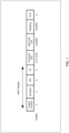
- FIG. 1 illustrates an exemplary Trigger frame.
- the Trigger frame includes a field (referred to as "Common Info field") that includes information common to a plurality of terminals (for example, also referred to as terminal common information) for a plurality of terminals to be frequency-multiplexed, and a field referred to as User Info List.
- a User Info field may include one or more fields (referred to as "User Info fields”) that include information individual (or specific) to a terminal (for example, also referred to as terminal-specific information).
- 11be may include, in the Trigger frame, a field (for example, a "Special User Info field") including information for a terminal corresponding to 11be (EHT) (not illustrated).
- a field for example, a "Special User Info field”
- EHT 11be
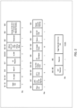
- FIG. 2 illustrates an exemplary configuration of a Common Info field studied in 11be (for example, EHT) (see, for example, NPL 4).
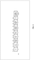
- FIG. 3 illustrates an exemplary configuration of a User Info field studied in 11be (EHT) (see, for example, NPL 5).
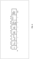
- FIG. 4 illustrates an exemplary configuration of a Special User Info field (see, for example, NPL 6).
- a terminal when a terminal receives a signal (for example, physical layer (PHY) protocol data unit (PPDU)) including a Trigger frame, and the Association ID (AID) of the terminal is specified in the User Info field in the Trigger frame, the terminal transmits an UL signal (for example, trigger-based PPDU (TB-PPDU)) in the indicated resource (RU) at the transmission timing after short interframe space (SIFS) from the PPDU end timing.
- a signal for example, physical layer (PHY) protocol data unit (PPDU)
- AID Association ID
- the terminal transmits an UL signal (for example, trigger-based PPDU (TB-PPDU)) in the indicated resource (RU) at the transmission timing after short interframe space (SIFS) from the PPDU end timing.
- PHY physical layer
- PPDU protocol data unit
- AID Association ID
- each of the plurality of terminals performs carrier sensing immediately before the transmission of a UL signal in a resource (for example, RA-RU) that can be allocated to a plurality of terminals
- the carrier sensing results of the plurality of terminals become Idle, and thus, the UL signals of the plurality of terminals possibly collide with each other.
- the scheduling of transmission RU of one or some of traffic types may be performed, by a Trigger frame, using a group identifier (for example, referred to as Group AID) of a group (for example, terminal group) including a plurality of terminals. Further, for example, varying the timing of transmitting a UL signal among a plurality of terminals in a terminal group can reduce collisions.
- a group identifier for example, referred to as Group AID
- the radio communication system may include, for example, AP 100 illustrated in FIG. 5 and terminal (STA) 200 illustrated in FIG. 6 . At least one of AP 100 and terminal 200 may exist two or more in a radio communication system.
- AP 100 groups a plurality of terminals including terminal 200 into a terminal group, and indicates, to terminal 200, terminal group information on the terminal group (for example, including an association between AID of a terminal and Group ID). Further, AP 100 transmits a Trigger frame that indicates the transmission of a UL signal limited to one or some of traffic types (for example, traffic for which low latency is required) to a terminal group including a plurality of terminals 200 defined in advance, for example.
- traffic types for example, traffic for which low latency is required
- Terminal 200 receives, for example, a Trigger frame and transmits a UL signal to AP 100 based on the radio resource (for example, transmission band (for example, RU) or signal length) and the transmission timing indicated by the received Trigger frame.
- the radio resource for example, transmission band (for example, RU) or signal length
- the traffic for which low latency is required is also referred to as Low Latency Traffic or Latency Sensitive Traffic, for example.
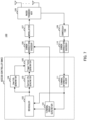
- FIG. 5 is a block diagram illustrating a configuration example of a part of AP 100 according to an embodiment of the present disclosure.
- a controller corresponding to, for example, control circuitry
- a control signal for example, Trigger frame
- identification information for example, Group association ID (AID)
- AID Group association ID
- a transmitter corresponding to, for example, transmission circuitry transmits the control signal.
- FIG. 6 is a block diagram illustrating a configuration example of a part of terminal 200 according to an embodiment of the present disclosure.
- a receiver corresponding to, for example, reception circuitry receives a control signal (Trigger frame) that indicates, using identification information (Group AID) common to a plurality of terminals 200 included in a terminal group, the allocation of a transmission resource for an uplink signal of one or some of a plurality of traffic types.
- a controller (corresponding to, for example, control circuitry) controls uplink transmission based on the control signal.
- AP 100 transmits, for example, terminal group information to terminal 200 and holds the terminal group information. Further, AP 100, for example, transmits a Trigger frame to terminal 200 indicating the transmission of predetermined traffic to a terminal group including a plurality of terminals 200.
- FIG. 7 is a block diagram illustrating a configuration example of AP 100.
- AP 100 illustrated in FIG. 7 may include, for example, terminal group generator 101, scheduler 102, Common Info generator 103, User Info generator 104, Trigger frame generator 105, error correction encoder 106, modulator 107, radio transceiver 108, demodulator 109, error correction decoder 110, and terminal information holder 111.
- terminal group generator 101 may be included in an access controller (for example, Medium Access Control (MAC) processor).
- MAC Medium Access Control
- terminal group generator 101 may be included in, for example, the controller illustrated in FIG. 5 .
- terminal group generator 101 may be included in, for example, the controller illustrated in FIG. 5 .
- radio transceiver 108 illustrated in FIG. 7 may be included in the transmitter illustrated in FIG. 5 , for example.
- terminal group generator 101 generates a terminal group including a plurality of terminals 200 based on the terminal information inputted from terminal information holder 111, and outputs information on the generated terminal group (for example, terminal group information) to error correction encoder 106 and scheduler 102.
- the terminal information may include, for example, Capability information of terminal 200, information on a transmission buffer state, and reception quality information.
- the Capability information may include, for example, information indicating whether terminal 200 supports transmission and reception of Low latency traffic.
- the information on the transmission buffer state may include, for example, information on the size of an uplink or downlink buffer for Low latency traffic addressed to AP 100 in terminal 200 or a delay requirement (delay budget or the like).
- the reception quality information may include, for example, a reception level of a signal, a Signal to Interference and Noise Ratio (SINR), or a path loss value measured by terminal 200.
- SINR Signal to Interference and Noise Ratio
- Terminal group generator 101 may, for example, select a plurality of terminals 200 that support transmission and reception of Low latency traffic based on the Capability information, and group the plurality of terminals 200 into a terminal group.
- the terminal group information may include, for example, information in which at least an AID of a terminal and a group identifier (for example, Group AID) are associated with each other, as illustrated in FIG. 8 .
- the terminal group information may be associated with, for example, at least one of traffic information (for example, Restricted UL Traffic ID (TID) Bitmap subfield) indicating a traffic type that permits terminal 200 in the terminal group to transmit a UL signal, and information on the timing of transmitting the UL signal (for example, transmission timing information), as illustrated in FIG. 9 .
- traffic information for example, Restricted UL Traffic ID (TID) Bitmap subfield
- TID Restricted UL Traffic ID
- transmission timing information for example, transmission timing information
- the traffic information for which transmission is permitted may be represented in a bitmap format as shown in FIG. 9 to indicate the transmission permission for each TID, for example.
- the Restricted UL TID Bitmap subfield may be represented by an 8-bit bitmap. Bits of the 8-bit bitmap may correspond to eight types of traffic (for example, TID numbers 0 to 7), respectively.
- TID numbers 0 to 7 For example, as illustrated in FIG. 9 , when "11000000" is indicated, terminal 200 can perform UL transmission of traffic data with TID numbers 0 and 1 (first and second), and cannot perform UL transmission of traffic data corresponding to other TID numbers.
- TID is related to the allowable delay amount
- specifying TID by the traffic information that permits transmission enables the configuration in which UL transmission in the traffic for which low latency is required is allowed and UL transmission in another traffic is not allowed.
- the information on the timing of transmitting a UL signal may include, for example, information on the offset of the timing of transmitting the UL signal with respect to the end timing of a PPDU including a Trigger frame.
- Terminal group generator 101 holds the generated terminal group information. Note that examples of terminal group information will be described later.
- terminal group generator 101 may generate a terminal group based on a part of the terminal information inputted from terminal information holder 111, for example.
- the terminal group may be defined based on the Capability information without considering the transmission buffer state and the reception quality of terminal 200.
- Scheduler 102 may perform scheduling for terminal 200, for example.
- scheduler 102 may allocate a radio resource (for example, including at least one of a transmission band and a signal length) to a terminal group including a plurality of terminals 200 based on the terminal group information inputted from terminal group generator 101 and the terminal information inputted from terminal information holder 111.
- a radio resource for example, including at least one of a transmission band and a signal length
- the transmission band allocated to a terminal group including a plurality of terminals 200 may be configured in at least a part of the transmission band of a PPDU including a Trigger frame.
- the transmission band may be configured (or limited) to, for example, a defined bandwidth (for example, 20 MHz ⁇ N (N is a natural number), or a natural number multiple of the bandwidth in which carrier sensing is performed).
- scheduler 102 may allocate a radio resource to a terminal group including a plurality of terminals 200 for each defined period.
- Scheduler 102 for example, outputs information on a terminal group including the determined plurality of terminals 200 and the allocation information on the radio resource to Common Info generator 103 and User Info generator 104.
- Common Info generator 103 may generate control information included in a Common Info field (for example, FIG. 2 ) common to plurality of terminals 200, for example.
- Common Info generator 103 may, for example, generate information of a Trigger type subfield and a CS Required subfield based on the allocation information of the radio resource inputted from scheduler 102.
- the Trigger Type subfield is a subfield that indicates, for example, the type of the Trigger frame (for example, the type of signal that AP 100 causes terminal 200 to transmit).
- AP 100 may indicate the Trigger Type of the Trigger frame indicating the allocation of a radio resource for the terminal group, as Basic.
- the Trigger Type of the Trigger frame indicating the allocation of a radio resource to the terminal group may be another Trigger Type different from Basic (for example, Beamforming Request Poll (BFRP), multi-user block ack request (MU-BAR), multi-user request to send (MU-RTS), Buffer Status Report Poll (BSRP), Groupcast with retries multi-user block ack request (GCR MU-BAR), Bandwidth Query Report Poll (BQRP), NDP Feedback Report Poll (NFRP), or the like).
- AP 100 may specify the Trigger Type of the Trigger frame as MU-RTS.
- the indication of allocating radio resources included in the Trigger frame and the UL transmission rule of an embodiment of the present disclosure may be applied to one or more frames (for example, transmission and reception of one or more data frames or Block Ack frames performed after the Trigger frame) over a TXOP (Transmission Opportunity) period.
- the Trigger frame may have a newly defined Trigger Type that specifies the indication of UL transmission limited to predetermined traffic (for example, Low Latency Traffic) by a terminal group.
- the CS Required subfield is a subfield that indicates to terminal 200 the necessity (or need) of executing carrier sensing before the transmission of a UL signal in response to a Trigger frame, for example.
- terminal 200 is indicated not to perform carrier sensing
- terminal 200 is indicated to perform carrier sensing.
- terminal 200 executes the carrier sensing before UL transmission, transmits the UL signal when the result of the carrier sensing is Idle, and cancels the UL signal transmission when the result of the carrier sensing is Busy.
- Common Info generator 103 may output information on the generated Common Info field to Trigger frame generator 105.
- Trigger frame configuration of a field (e.g., subfield) in a Trigger frame may be replaced with another term such as “definition” or “interpretation,” for example.
- User Info generator 104 may generate, for example, control information included in a Special User Info field or a User Info field individual to terminal 200.
- User Info generator 104 may generate, for example, information on a Special User Info field or a User Info field individual to terminal 200 based on a defined format, as illustrated in FIGS. 3 and 4 , and may generate information on a User Info List including a User Info field for each of a plurality of terminals 200.
- User Info generator 104 may output the information on the User Info List to Trigger frame generator 105, for example.
- User Info generator 104 may generate a User Info List by arranging, for example, a plurality of User Info fields in a defined order according to the type of allocation RU. For example, User Info generator 104 may generate a User Info List by prioritizing (e.g., arranging in an earlier order) a User Info field indicating at least one of allocation RU limited to predetermined traffic and allocation RU for a terminal group over a User Info field indicating another allocation RU.
- an AID12 subfield in the User Info field may include an identifier of a terminal group including terminal 200 (for example, Group AID illustrated in FIGS. 8 and 9 ).
- User Info generator 104 may generate, for example, an RU Allocation subfield based on the allocation information of the radio resource inputted from scheduler 102.
- the format of the User Info field may be changed (or switched, configured) depending on the value of the AID12 subfield (for example, whether the value is a terminal group identifier or not).
- the format of the User Info field corresponding to the Group AID of the terminal group and the format of the User Info field corresponding to the AID individual to terminal 200 may be different from each other.
- the format illustrated in FIG. 3 may be applied.
- the format illustrated in FIG. 10 may be applied.
- the value of the AID12 subfield indicates a terminal group
- information not included in the terminal group information for example, MCS information or information on traffic for which transmission is permitted
- the bit positions (for example, B20-B24) of the "UL FEC Coding Type subfield" and the "UL EHT-MCS subfield” indicating information on the Modulation and Coding Scheme (MCS) of the UL signal in the format of the User Info field illustrated in FIG. 3 may be changed to the "Transmission timing information subfield” indicating the transmission timing information of the UL signal in the format of the User Info field illustrated in FIG. 10 .
- the MCS used for each terminal group (for example, Group AID) may be defined in the terminal group information and may be indicated to terminal 200 in advance.
- terminal 200 configures the MCS included in the terminal group information, so that the UL FEC Coding Type subfield and the UL EHT-MCS subfield are not necessary in the Trigger frame, and the transmission timing information of the UL signal can be included in the bit positions of these subfields.
- one timing may be configured for each of a plurality of terminals 200 (for example, STA1 to STA3 and STA4 to STA6) in the terminal group, as illustrated in FIG. 11 .
- a plurality of timing candidates may be configured for each of a plurality of terminals 200 (for example, STA1, STA2, and STA3) in the terminal group, as illustrated in FIG. 12 .
- pattern numbers pattern 1 to 3 for the offset for each terminal 200 constituting the terminal group is configured.
- AP 100 can dynamically indicate the transmission timing information (for example, any one of a plurality of pattern numbers) of each terminal 200 by the Trigger frame, thereby enhancing the fairness of UL transmission opportunities among terminals 200.
- the information on the band allocated to the terminal group including terminal 200 may be, for example, configured (for example, limited) to a frequency resource position of 20 MHz ⁇ N (for example, an integer multiple of 20 MHz) allocated to terminal 200.
- a method for indicating a frequency resource position of 20 MHz ⁇ N a method for indicating a frequency resource of a clear to send (CTS) frame by a multi-user request to send (MU-RTS) used in 11ax may be applied.
- CTS clear to send
- MU-RTS multi-user request to send
- a "UL Bandwidth Extension subfield" included in the Special User Info field illustrated in FIG. 4 may be used, for example.
- the combination of the UL BW subfield in the Common Info field and the UL Bandwidth Extension subfield in the Special User Info field may indicate the Operation bandwidth to terminal 200.
- the Special User Info field may include control information for terminal 200 and a terminal group including terminal 200.
- User Info generator 104 may, for example, output information on the generated User Info List to Trigger frame generator 105.
- Trigger frame generator 105 may generate a Trigger frame including information of a Common Info field inputted from Common Info generator 103 and information of a User Info List (for example, Special User Info field and at least one User Info field) inputted from User Info generator 104, based on the format illustrated in FIG. 1 , for example.
- the Trigger frame may include, for example, at least one of a MAC header, Padding, and a frame check sequence (FCS), in addition to the Common Info field and the User Info List.
- Trigger frame generator 105 may, for example, output the generated Trigger frame to error correction encoder 106.
- Error correction encoder 106 performs error correction encoding on a transmission data signal including, for example, terminal group information inputted from terminal group generator 101 or a transmission data signal including a Trigger frame inputted from Trigger frame generator 105, and outputs the encoded signal to modulator 107.
- the transmission order of the terminal group information and the Trigger frame may be as follows. For example, AP 100 indicates the terminal group information to terminal 200 first. Then, AP 100 indicates to terminal 200 the Trigger frame that indicates UL transmission to the terminal group.
- Modulator 107 for example, performs modulation processing on the signal inputted from error correction encoder 106, and outputs the modulated signal to radio transceiver 108.
- AP 100 may form the OFDM signal by mapping the modulated signal to a defined frequency resource, performing inverse fast Fourier transform (IFFT) processing to convert the signal into a time waveform, and adding a cyclic prefix (CP).
- IFFT inverse fast Fourier transform
- Radio transceiver 108 performs radio transmission processing, such as D/A conversion and up-conversion to a carrier frequency, on the modulated signal inputted from modulator 107, and transmits the signal after the radio transmission processing to terminal 200 via an antenna. Further, radio transceiver 108 receives a signal transmitted from, for example, terminal 200 via an antenna, performs radio reception processing such as down-conversion to a baseband and A/D conversion on the received signal, and outputs the signal after the radio reception processing to demodulator 109.
- radio transmission processing such as D/A conversion and up-conversion to a carrier frequency
- Demodulator 109 performs, for example, demodulation processing on the signal inputted from radio transceiver 108, and outputs the demodulated signal to error correction decoder 110.
- AP 100 for example, demodulator 109 may perform CP removal processing and fast Fourier transform (FFT) processing.
- Error correction decoder 110 decodes the signal inputted from demodulator 109 to obtain the received data signal from terminal 200. Error correction decoder 110 outputs the decoded data including the terminal information to terminal information holder 111 in a case where the terminal information described above is included in the received data after decoding, for example.
- Terminal information holder 111 may acquire (or hold), for example, terminal information (for example, Capability information of terminal 200, transmission buffer state, and information on reception quality may be included) from the decoded data inputted from error correction decoder 110, and may output the acquired terminal information to terminal group generator 101 and scheduler 102.
- terminal information for example, Capability information of terminal 200, transmission buffer state, and information on reception quality may be included
- Terminal 200 receives, for example, terminal group information from AP 100 and holds the terminal group information. Further, terminal 200 receives a Trigger frame for scheduling an RU for Low latency Traffic transmission using, for example, a group identifier (for example, Group AID) of a terminal group, and transmits a UL signal to AP 100 in response to the Trigger frame.
- a group identifier for example, Group AID
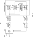
- FIG. 13 is a block diagram illustrating a configuration example of terminal 200.
- Terminal 200 illustrated in FIG. 13 may include, for example, radio transceiver 201, demodulator 202, error correction decoder 203, Common Info acquirer 204, terminal group information holder 205, User Info acquirer 206, data generator 207, error correction encoder 208, and modulator 209.
- At least one of Common Info acquirer 204, Terminal group information holder 205, User Info acquirer 206, and Data generator 207 may be included in an access controller (for example, MAC processor).
- an access controller for example, MAC processor
- demodulator 202 error correction decoder 203, Common Info acquirer 204, terminal group information holder 205, User Info acquirer 206, data generator 207, error correction encoder 208, and modulator 209 illustrated in FIG. 13 may be included in, for example, the controller illustrated in FIG. 6 .
- radio transceiver 201 illustrated in FIG. 13 may be included in, for example, the receiver illustrated in FIG. 6 .
- Radio transceiver 201 receives a reception signal via an antenna and performs, on the received signal, radio reception processing such as down-conversion and/or A/D conversion, and outputs the signal after the radio reception processing to demodulator 202.
- radio reception processing such as down-conversion and/or A/D conversion
- radio transceiver 201 performs radio transmission processing such as up-conversion and/or D/A conversion on a signal inputted from modulator 209, and transmits the signal after the radio transmission processing via an antenna.
- radio transceiver 201 may determine the transmission timing based on information (for example, information on the transmission timing) inputted from terminal group information holder 205, and may transmit a signal from the antenna in accordance with the determined transmission timing.
- Demodulator 202 performs demodulation processing on the received data inputted from radio transceiver 201, and outputs the demodulated signal to error correction decoder 203.
- terminal 200 e.g., demodulator 202 may perform CP removal processing and FFT processing.
- Error correction decoder 203 may, for example, decode the demodulated signal inputted from demodulator 202 and output the decoded signal as a received data signal. Further, error correction decoder 203, for example, outputs a Trigger frame in the received data signal to Common Info acquirer 204 and User Info acquirer 206. Further, error correction decoder 203 outputs, for example, a frame including terminal group information in the received data signal to terminal group information holder 205.
- Common Info acquirer 204 may, for example, extract information corresponding to a Common Info field from the Trigger frame inputted from error correction decoder 203, and acquire terminal common information.
- the terminal common information may include, for example, information on a channel allocated to terminal 200. Note that information on a period allocated to terminal 200 may be included as terminal common information. Further, the terminal common information may include, for example, a Trigger Type subfield and a CS Required subfield. In a case where the value of the Trigger Type subfield corresponds to a type that indicates UL transmission by a terminal group limited to predetermined traffic (for example, Low Latency Traffic), terminal 200 may change the interpretation of the format of the User Info field from the format of the Basic type. Further, in a case where the CS Required subfield value is 1, terminal 200 executes carrier sensing before UL transmission. The period for executing carrier sensing is, for example, a period from the end timing of a PPDU including a Trigger frame to a predetermined UL transmission timing indicated in advance by AP 100 (or indicated in the Trigger frame).
- Common Info acquirer 204 may output the extracted terminal common information to User Info acquirer 206.
- Terminal group information holder 205 acquires and holds the terminal group information from a frame including the terminal group information inputted from error correction decoder 203.
- the terminal group information may include, for example, information in which at least a terminal AID and a terminal group identifier (for example, Group AID) are associated with each other, as illustrated in FIGS. 8, 9 , 11, or 12 .
- transmission timing information (Offset) of each terminal 200 in the terminal group may be associated with the terminal group information, for example.
- terminal group information holder 205 may output the held information to User Info acquirer 206, data generator 207, and radio transceiver 201.
- User Info acquirer 206 may, for example, extract information corresponding to a User Info List (for example, at least one User Info field and a Special User Info field) from the Trigger frame inputted from error correction decoder 203, and may perform processing of receiving the User Info field based on the terminal common information (for example, including Trigger Type) inputted from Common Info acquirer 204 and the information inputted from terminal group information holder 205.
- a User Info List for example, at least one User Info field and a Special User Info field
- Terminal common information for example, including Trigger Type
- User Info acquirer 206 determines the presence or absence of UL transmission indication to a terminal group including terminal 200, by comparing the terminal identification information (for example, AID12 subfield) included in the User Info field and the terminal group identifier (for example, Group AID) inputted from terminal group information holder 205 with each other.
- User Info acquirer 206 may identify the format of the User Info field depending on the presence or absence of UL transmission indication to the terminal group. Then, User Info acquirer 206 acquires terminal-specific information (for example, information on allocation of a radio resource, transmission power information, UL signal length, and/or the like) from the User Info field.
- the signal length of the UL signal may be determined based on, for example, the time length indicated in the UL Length subfield of the Trigger frame.
- User Info acquirer 206 may output, for example, the terminal-specific information and terminal common information to data generator 207.
- Data generator 207 acquires traffic information for which UL transmission is permitted based on the information inputted from terminal group information holder 205 and the information inputted from User Info acquirer 206, for example. Data generator 207 performs data generation processing, for example, in a case where traffic data permitted by AP 100 is held. On the other hand, in a case where the traffic data permitted by AP 100 is not held, data generator 207 may stop the subsequent processing (for example, not transmit UL signal) in data generator 207.
- data generator 207 when data generator 207 executes data generation, data generator 207 outputs the generated data signal (for example, UL signal to AP 100) to error correction encoder 208.
- the UL signal may be, for example, a response signal to a Trigger frame and may be generated in a TB-PPDU format.
- Error correction encoder 208 performs error correction encoding on the data signal inputted from data generator 207, and outputs the encoded signal to modulator 209. Note that the encoding rate for the data signal may be determined depending on, for example, the terminal-specific information inputted from User Info acquirer 206.
- Modulator 209 modulates the signal inputted from error correction encoder 208, and outputs the modulation signal to radio transceiver 201.
- the modulation scheme applied in modulator 209 may be determined depending on the terminal-specific information inputted from User Info acquirer 206, for example.
- terminal 200 for example, modulator 209 may form an OFDM signal by mapping the modulation signal to a frequency resource, performing the IFFT processing, and adding a CP.
- terminal 200 may acquire the transmission timing information from, for example, User Info acquirer 206 (not illustrated), and may transmit a signal from the antenna in accordance with the transmission timing indicated in the transmission timing information.
- AP 100 generates terminal group information and indicates the generated terminal group information to a plurality of terminals 200 (for example, Non-AP terminals) included in the terminal group. Further, AP 100, for example, indicates UL transmission at a predetermined transmission timing to one or more terminals 200, using a Trigger frame including terminal group information shared with terminal 200.
- AP 100 can, for example, allocate the same radio resource (for example, RA-RU) to a plurality of terminals 200, permit UL transmission for terminal 200 that holds Low Latency Traffic, and prohibit UL transmission for terminal 200 that does not hold Low Latency Traffic.
- terminal 200 can transmit a UL signal without transmitting an indication of the transmission buffer (request for transmission resource) from terminal 200 to AP 100, thereby reducing the delay.
- the collision of UL signals can be reduced by varying the transmission timings among terminals 200 in the terminal group, and, for example, AP 100 can receive a signal from one terminal 200.
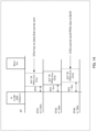
- FIG. 14 illustrates exemplary operations of AP 100 and terminal 200 according to the present embodiment.
- FIG. 14 illustrates an example in which the traffic information (for example, Restricted UL TID Bitmap subfield) for which transmission is permitted includes Low latency Traffic.
- the traffic information for example, Restricted UL TID Bitmap subfield
- STA1 does not hold Low Latency Traffic. Thus, STA1 determines that the transmission of a UL signal is not permitted based on the Restricted UL TID Bitmap, and does not transmit the UL signal.
- Bitmap SIFS + 9us
- STA3 holds Low Latency Traffic.
- STA3 determines that the transmission of a UL signal is permitted based on the Restricted UL TID Bitmap.
- the result of the carrier sensing is Busy due to the detection of the signal from STA2 by the carrier sensing until the transmission timing, and thus STA3 does not transmit the UL signal.
- the transmission for one or some of (defined) traffic types for example, Low latency Traffic
- the transmission for other traffic types is not permitted.
- the traffic type of the signal to be UL-transmitted is limited, thereby reducing the collision of UL signals among terminals 200.
- the timing of transmitting the UL signal configured for each terminals 200 is different. This makes it possible to reduce the collision of UL signals with Low Latency Traffic among terminals 200 in the resource allocated to a plurality of terminals 200.
- the allocation resource size (for example, transmission resource size of UL signal) may be set to 20 MHz ⁇ N (for example, integer multiple of 20 MHz).
- the UL signal length (for example, the time length of PPDU) can be shortened, and the delay can be reduced.
- an embodiment of the present disclosure can be applied without changing the specification of carrier sense in 20 MHz units defined in the existing standard (for example, such as 11ax, 11be).
- the allocation resource size may be set to 20 MHz or less.
- terminal 200 may execute carrier sensing before UL transmission in the transmission RU, and need not execute carrier sensing in an RU different from the transmission RU.
- the allocation resource is 20 MHz or less, for example, UL signals with different transmission timings can be frequency-multiplexed in a 20 MHz band.
- the terminal group information may include, for example, information indicating a correspondence between at least an AID for each terminal and a group identifier (for example, Group AID), as illustrated in FIG. 8 .
- At least one of traffic information (for example, Restricted UL TID Bitmap subfield) indicating one or some of the traffic types that permit transmission, transmission timing information of a UL signal (for example, Offset subfield), and MCS information (for example, MCS subfield) may be configured (or may be associated).
- traffic information for example, Restricted UL TID Bitmap subfield
- MCS information for example, MCS subfield
- AP 100 may, for example, extract terminals 200 that support transmission and reception of Low latency traffic based on the Capability information of terminal 200, and group the extracted terminals into a terminal group. Further, AP 100 may, for example, extract terminals 200 that hold an uplink or downlink buffer of Low latency traffic among terminals 200 of which Capability supports transmission and reception of Low latency traffic, and group the extracted terminals into a terminal group. Note that the uplink/downlink buffer state of Low latency traffic for terminal 200 may be indicated to AP 100, for example, by terminal 200 reporting each traffic size including the delay requirement to AP 100 using BSR.
- Capability information related to Low Latency Traffic for terminal 200 may be indicated to AP 100, for example, by being included in the Capability information in the Association Request frame.
- AP100 can, for example, identify (or grasp) the Capability of a terminal from an Association Request frame and generate terminal group information.
- terminal 200 may determine whether to respond to the Trigger frame based on the Capability of terminal 200, for example. For example, when terminal 200 that does not support the transmission and reception of Low Latency Traffic detects a Trigger Type that specifies the indication of UL transmission by a terminal group limited to predetermined traffic, terminal 200 may stop the UL transmission processing including the subsequent decoding processing for the Trigger frame.
- the Reserved bit of the AID12 subfield may be used, as illustrated in FIGS. 8, 9 , 11, and 12 .
- an AID for example, any of 1 to 2007
- an AID used for an Associated STA may be used instead of the Reserved bit of the AID12 subfield, for example.
- AP 100 does not use the AID used as the terminal group number as an individual AID for each terminal 200 (hereinafter, referred to as individual AID), for terminal 200 supporting beyond 11be (for example, beyond 11be terminal).
- individual AID for terminal 200 supporting beyond 11be
- AP 100 may use an AID used as a terminal group number for beyond 11be terminal, as an individual AID for a terminal that does not have a function of acquiring terminal group information (for example, terminal of existing standard).
- the terminal group number may be configured in an AID indicating an RA-RU to a plurality of terminals 200 (for example, 0, 2045), for example.
- OBO OFDMA random access backoff
- a terminal that supports only the existing standard (for example, 11ax, 11be) and a beyond 11be terminal that supports a standard (for example, Beyond 11be) supporting the operation according to the present embodiment may be included in the same terminal group.
- AP 100 can schedule a common RU for a terminal that does not support beyond 11be and a beyond 11be terminal with one AID.
- the Beyond 11be terminal may transmit a UL signal with a transmission timing delayed by a configured offset from SIFS (for example, SIFS + 9us).
- SIFS for example, SIFS + 9us
- the transmission timing of a terminal that supports only the existing standard does not support the operation of the present embodiment, and thus, the timing of transmitting the UL signal is fixed to SIFS. Accordingly, for example, in a case where a terminal that supports only the existing standard does not transmit a UL signal, the transmission of a UL signal by a Beyond 11be terminal is possible by the carrier sensing of the Beyond 11be terminal, which makes it possible to avoid a collision of UL signals and to effectively utilize radio resources.
- a plurality of Group AIDs may be defined (specified or configured) for one terminal 200.
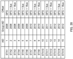
- a plurality of Group AIDs (for example, 2008 and 2009) may be defined for one terminal 200 (for example, each of STA1, STA2, and STA3).
- different traffic information, different transmission timing information, or different MCS information may be associated with each Group AID.
- AP 100 can, for example, flexibly change the traffic type for UL transmission, the transmission timing for determining the priority of each terminal 200, or the MCS, by the Group AID included in the Trigger frame for the same terminal 200, and can indicate the transmission of the UL signal.
- the UL transmission timing is not limited to being individually configured for each terminal 200 in the terminal group as in FIGS. 11, 12 , and 16 .
- a plurality of UL transmission timings (candidates for the transmission timing) is configured in the terminal group information, and a transmission timing may be randomly selected for each terminal 200 from the plurality of candidates.
- Terminal 200 may, for example, randomly select (or apply) and use one transmission timing from a plurality of transmission timings (transmission timing candidates).
- a plurality of transmission timings for example, SIFS, SIFS + 9us, and SIFS + 18us
- Terminal 200 for example, randomly selects and uses one transmission timing from a plurality of transmission timings defined in terminal group information, thereby equalizing the priority of transmission data among a plurality of terminals 200 and enhancing fairness among terminals 200.
- the number of patterns of transmission timings may vary depending on the number of terminals included in the terminal group. For example, the larger the number of terminals included in the terminal group, the more patterns (for example, candidates) of the timing of transmitting the UL signal may be configured. For example, in a case where the number of terminals in the terminal group is three or less, three patterns of transmission timings may be defined as illustrated in FIG. 17 , and in a case where the number of terminals in the terminal group is four or more, six patterns of transmission timings may be defined as illustrated in FIG. 18 . As described above, by changing the number of patterns of selectable transmission timings based on the number of terminals constituting the terminal group, it is possible to keep the transmission timing within a predetermined time and to improve fairness among terminals 200.
- the selectable transmission timing set may vary depending on the traffic information (for example, TID) for which transmission is permitted.
- a transmission timing set including an earlier transmission timing may be configured for a traffic type with a higher priority (for example, traffic that requires low latency).
- a traffic type with a higher priority for example, traffic that requires low latency
- the UL transmission timing in the range of SIFS to SIFS+18us is defined, and in a case of a traffic type (00110000 in FIG. 19 ) with a lower priority, the UL transmission timing in the range of SIFS+18us to SIFS+35us is defined.
- the probability that the UL transmission timing becomes earlier increases as the priority of the traffic type becomes higher, and thus, the delay in UL transmission can be reduced.
- AP 100 may indicate to terminal 200 whether to randomly select the transmission timing of the UL signal or to be indicated by AP 100, by including the indication in the User Info field.
- AP 100 may generate terminal group information that specifies a random selection (pattern 4) by terminal 200 in addition to the transmission timing (pattern 1 to pattern 3) indicated to each terminal 200 in the terminal group, as illustrated in FIG. 20 .
- AP 100 may indicate any of pattern 1 to pattern 4 to terminal 200 using two bits of the User Info field.
- AP 100 can indicate the UL transmission timing of each terminal 200 depending on the communication situation of each terminal 200, for example, and thus, the fairness among terminals 200 can be improved. For example, in a case where there is a difference in throughput among terminals 200, the transmission timing of terminal 200 with low throughput is advanced, so that the UL transmission of terminal 200 with low throughput can be prioritized and the throughput can be improved. Further, for example, in a case where the difference in throughput among terminals 200 is small, fairness among terminals 200 can be maintained by indicating random selection.
- AP 100 may indicate, to terminal 200, a timing earlier than the end timing of SIFS (for example, offset of SIFS - 6us with respect to the end timing of PPDU including Trigger frame) as the timing of transmitting the UL signal.
- AP 100 can cause terminal 200 having a Capability of responding at a timing earlier than the end timing of SIFS, to preferentially transmit a UL signal by indicating a timing earlier than the end timing of SIFS.
- the indication of the transmission timing need not be included in the terminal group information.
- the transmission timing depending on the Access Category (AC) of the traffic for which UL transmission is permitted may be defined in the standard, or may be configured in a pre-negotiation between AP 100 and terminal 200.
- the transmission timing depending on four differentACs may be configured as follows based on the delay required for each AC. Since the traffic ID (TID) and the AC have a correspondence with each other in advance, AP 100 can indicate the traffic for which UL transmission is permitted with the TID, which allows terminal 200 to select the transmission timing depending on the TID.
- TID traffic ID
- AP 100 can indicate the traffic for which UL transmission is permitted with the TID, which allows terminal 200 to select the transmission timing depending on the TID.
- the "AID" of the AID and Group AID described in an embodiment of the present disclosure is not limited to an Association identifier configured by AP 100 for a Non-AP terminal.
- the AID may indicate various IDs and values used in the AID12 subfield of the Trigger frame.
- the AID may be referred to as a terminal ID or a Group ID.
- the Group AID may be an ID for identifying one or more terminals 200 to which transmission of a UL signal (including Low latency traffic) is indicated by a Trigger frame.
- the existing frame may be used for the definition of Group AID.
- the terminal group information may be indicated to a plurality of terminals 200 from AP 100 using a Management frame (for example, referred to as new Management frame) different from the existing frame, for example.
- a Management frame for example, referred to as new Management frame
- the new Management frame may include a Field indicating whether terminal 200 to be indicated (transmission destination) (referred to as, for example, "Membership Status field") is included in each of a plurality of terminal groups.
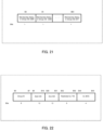
- FIG. 21 illustrates an exemplary Membership Status field.
- the terminal group information is individually indicated to each terminal 200.
- traffic information for example, Restricted UL TID Bitmap
- Restricted UL TID Bitmap for which transmission is permitted may be indicated to terminal 200 using 8 bits for each of a plurality of Group AIDs.
- a terminal group ID (Group AID or Group ID), a set of terminal IDs belonging to the terminal group (for example, terminals whose terminal AIDs are Start AID to End AID), traffic information for which transmission is permitted (for example, Restricted UL TID), and MCS information used for a UL signal (for example, UL MCS) may be indicated to a plurality of terminals 200 collectively.
- the terminal group information is indicated to a plurality of terminals 200 collectively.
- the new Management frame illustrated in FIG. 22 is merely an example and is not limited thereto.
- the new Management frame may include at least a Group ID and a set of terminal IDs (for example, Start AID and End AID).
- a method for individually indicating terminal group information to each terminal can generate a terminal group flexibly compared to a method for indicating the terminal group information to a plurality of terminals 200 collectively (for example, FIG. 22 ). Further, a method for indicating the terminal group information to a plurality of terminals 200 collectively (for example, FIG. 22 ) can reduce the amount of signaling compared to a method for individually indicating the terminal group information to each terminal (for example, FIG. 21 ).
- the existing frame may be used (or reused) for the indication of the terminal group information.
- the terminal group information may be indicated to terminal 200 by using the Group ID management frame of IEEE 11ac or the Restricted Access Window (RAW) Parameter Set (RPS) element format of IEEE 11ah.
- RAW Restricted Access Window
- RPS Parameter Set
- the terminal group information may be included in a beacon of AP 100, for example, and may be indicated to a plurality of terminals 200 connected to AP 100 as broadcast information.
- terminal group information may be added and indicated to terminal 200 in a negotiation procedure for Low latency traffic in which a TID and a delay requirement (for example, delay budget) for the traffic of the TID are associated with each other (for example, Request/Response for new Action frame or extension of Add Block Acknowledgment (ADDBA) or the like).
- a TID and a delay requirement for example, delay budget
- ADDBA Add Block Acknowledgment
- Trigger frame generation processing in AP 100 for example, Common Info generator 103, User Info generator 104, and Trigger frame generator 105 will be described. Further, the processing of transmitting a UL signal based on the terminal group information in terminal 200 (for example, terminal group information holder 205 and radio transceiver 201) will be described.
- one Trigger frame may include a plurality of User Info fields (terminal-specific information) corresponding to the same Group AID (for example, identification information common to a plurality of terminals 200).
- AP 100 may include transmission timing information (for example, Transmission timing information subfield) in the User Info field, and may indicate that different transmission timings are used among terminals 200 in the terminal group.
- transmission timing information included in the User Info field may be, for example, a pattern number for the transmission timing as illustrated in FIG. 12 or FIG. 20 .
- STA1 does not hold traffic data indicated by terminal group information
- STA2 and STA3 hold traffic data indicated by the terminal group information.
- STA2 and STA3 attempt UL transmission.
- the transmission timings in RU1 and RU2 for STA2 are "SIFS + 9us” and “SIFS + 18us,” respectively.
- the transmission timings in RU1 and RU2 for STA3 are "SIFS + 18us” and "SIFS,” respectively.
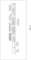
- STA2 and STA3 may select a radio resource with a smaller (earlier) transmission timing from the plurality of radio resources. For example, in the above-described example, as illustrated in FIG. 23 , STA2 may select RU1, which has the earlier transmission timing of "SIFS + 9us” between the transmission timing of "SIFS + 9us” in RU1 and the transmission timing of "SIFS + 18us” in RU2, and may transmit a UL signal (for example, EHT TB PPDU) at the transmission timing of "SIFS + 9us" in RU1.
- a UL signal for example, EHT TB PPDU
- STA3 may select RU2, which has the earlier transmission timing of "SIFS” between the transmission timings of "SIFS + 18us" in RU1 and “SIFS” in RU2, and may transmit a UL signal (for example, EHT TB PPDU) at the transmission timing of "SIFS" in RU2.
- a UL signal for example, EHT TB PPDU
- the carrier sensing executed before UL transmission may be executed in a subchannel including an RU to be transmitted by each terminal 200, for example.
- STA2 may perform carrier sensing in RU1 and need not perform carrier sensing in RU2.
- STA3 may perform carrier sensing in RU2 and need not perform carrier sensing in RU1.
- the result of the carrier sensing for RU1 becomes Idle even when RU2 is used for STA3, so that STA2 can transmit an uplink signal in RU1.
- terminal 200 may select one RU randomly from the plurality of RUs with the same transmission timing, for example. The random selection can maintain the fairness of transmission opportunities.
- the procedure in which terminal 200 selects one RU from a plurality of RU candidates may be as follows.
- terminal 200 may calculate the time length of the Packet extension (PE) field, which is the field at the end of the TB-PPDU constituting a UL signal, based on the UL transmission timing (offset amount).
- PE Packet extension
- terminal 200 may, for example, prioritize the RU indicated by the User Info field in which the individual AID is configured, and may apply the SIFS offset to transmit the UL signal.
- the delay can be reduced by individually allocating a radio resource to terminal 200 by an individual AID.
- terminal 200 may, for example, prioritize the RU indicated by the User Info field in which the Group AID is configured, and may apply the offset corresponding to the terminal group information to transmit the UL signal.
- interference of signals among terminals 200 may occur in the reception processing of AP 100.
- OFDM modulation is applied to UL signals
- the orthogonality of OFDM is possibly lost and interference possibly occurs when the transmission timing of terminal 200 exceeds the CP length.
- exemplary UL transmission methods for example, Transmission Method 1 and Transmission Method 2 that reduce interference will be described below.
- Transmission Method 1 is a method of configuring a guard band at the boundary of 20 MHz ⁇ N in an RU indicated by Group AID.
- a guard band for example, a non-transmission section
- a predetermined number of Tones may be applied to the boundary of 242 tones (20 MHz channel).
- AP 100 performs reception processing per allocation RU (for example, 20 MHz ⁇ N) of each of the plurality of terminals 200, for example.
- allocation RU for example, 20 MHz ⁇ N
- a guard band is configured at the boundary with another resource, and thus, AP 100 can reduce the influence of interference in a case where UL signals transmitted by a plurality of terminals 200 at different timings are frequency-multiplexed.
- Transmission Method 2 is a method (for example, newly defined method) in which a TB-PPDU format including a UL signal in response to a Trigger frame including a Group AID is different from the existing TB-PPDU format.
- the format of a UL signal (for example, EHT TB-PPDU for Group AID) assigned by a User Info field corresponding to a Group AID (for example, identification information common to a plurality of terminals 200) and the format of a UL signal (for example, an EHT TB-PPDU) assigned by a User Info field corresponding to an AID individual to terminal 200 may be different from each other.
- a PPDU format in which the number of Repetitions of a predetermined symbol in the UL signal is changed depending on the offset amount (or transmission timing) configured for each terminal 200 in the terminal group may be applied to the format of the EHT TB-PPDU for Group AID.
- the number of Repetitions of the RL-SIG symbol may be configured to be larger as the offset amount from the end timing of the PPDU including the Trigger frame is smaller.
- the difference in the timing of receiving an OFDM symbol after U-SIG in AP 100 can be reduced within the CP length regardless of the offset amount, thereby preventing the occurrence of interference.
- AP 100 can perform FFT processing on a band including all allocation RUs for a plurality of terminals 200 at once, for example.
- a PPDU format in which the time length of a predetermined symbol (for example, L-STF) in a UL signal is changed depending on the offset amount (or transmission timing) configured for each terminal 200 in the terminal group may be applied.
- the L-STF symbol length may be configured to be longer by repeating a predetermined sequence as the offset amount from the end timing of the PPDU including the Trigger frame is smaller.
- the difference in the timing of receiving an OFDM symbol after U-SIG in AP 100 can be reduced within the CP length regardless of the offset amount, thereby preventing the occurrence of interference.
- AP 100 can perform FFT processing on a band including all allocation RUs for a plurality of terminals 200 at once, for example.
- the above describes an example of a UL transmission method that reduces interference.
- the 11ax and 11be each have a rule for the transmission order (or priority) of the User Info fields in the Trigger frame that the User Info fields are transmitted in the following order based on the RU indicated by each User Info field.
- AP 100 transmits information of the User Info fields in the Trigger frame in accordance with this rule. This allows terminal 200 to start the processing of generating a high-priority UL signal early.
- the transmission order for RU allocation (for example, referred to as "RU allocation by Group AID") limited to predetermined traffic (for example, Low Latency Traffic) for a terminal group may be newly defined.
- the transmission order (or priority) of the User Info fields in the Trigger frame may be based on the RU indicated by each User Info field, and the transmission rule may be as follows. In the following rule, the User Info field indicating RU allocation by Group AID may be configured earlier than the User Info field indicating another RU.
- the transmission order of the User Info field corresponding to the Group AID may be earlier than the transmission order of the User Info field corresponding to the AID individual to terminal 200.
- terminal 200 can complete the processing of decoding the User Info field including the transmission indication for Low latency Traffic early, and can start the preparation for UL transmission early. This makes it possible to reduce the delay in Low Latency Traffic.
- AP 100 may allocate an RU of 20 MHz or less to Low latency Traffic.
- AP 100 may schedule 15 terminals 200 (for example, 3 terminals/RU) in 5 RUs within 20 MHz, as illustrated in FIG. 29 .
- the signals of terminals 200 for which an earlier transmission timing is configured among terminals 200 having data can be frequency-multiplexed.
- STA1 and STA10 can be frequency multiplexed in RUs of 20 MHz or less (for example, RU1 and RU4).
- an RU of 20 MHz or less is allocated to Low latency Traffic. Consequently, for example, the transmission of another terminal 200 is prioritized, resulting in the carrier sense being Busy, which reduces the impact of not being capable of transmitting a UL signal.
- a large number of terminals 200 can be efficiently allocated in a small number of radio resources.
- the specification may be changed such that the carrier sense immediately before UL transmission by terminal 200 is executed in an RU band of 20 MHz or less.
- UL signals with different transmission timings can be frequency-multiplexed even in 20 MHz or less.
- AP 100 generates a Trigger frame that indicates the allocation of a transmission resource for a UL signal of one or some of the plurality of traffic types, using an AID (Group AID) common to a plurality of terminals 200 included in a terminal group, and transmits the Trigger frame to terminal 200. Further, terminal 200 receives a Trigger frame that indicates the allocation of a transmission resource for a UL signal of one or some of the plurality of traffic types using a Group AID common to a plurality of terminals 200 included in a terminal group, and controls UL transmission based on the Trigger frame.
- AID Group AID
- terminal 200 can perform UL transmission limited to the one or some of traffic types (for example, traffic for which low latency is required), and thus, it is possible to reduce the collision of UL signals among a plurality of terminals 200 and to reduce the delay without increasing the resource that can be allocated to the terminal group.
- traffic types for example, traffic for which low latency is required
- both the allocation of a UL transmission resource limited to UL transmission of one or some of traffic types (for example, the configuration of Restricted UL TID) and the configuration of the timing of transmitting a UL signal (for example, the configuration of Offset) are associated with terminal group information, but the present disclosure is not limited thereto.
- the allocation of a UL transmission resource limited to UL transmission of one or some of traffic types (for example, the configuration of Restricted UL TID) may be configured, and the timing of transmitting a UL signal need not be configured. Even in this case, the collision of UL signals can be reduced and the delay can be reduced by limiting the traffic type.
- the timing of transmitting a UL signal may be configured, and the allocation of a UL transmission resource limited to UL transmission of one or some of traffic types need not be configured. Even in this case, the difference in the timing of transmitting the UL signal can reduce the collision of UL signals and reduce the delay.
- traffic types are not limited to traffic for which low latency is required (for example, Low latency Traffic), and may be another traffic type.
- parameters such as a transmission timing (Offset), the value of Restricted UL TID Bitmap, a Group AID, an AID individual to terminal 200, the number of terminals included in the terminal group, a resource size, and the number of resources are merely examples, and other values may be used.
- the field indicating information on the terminal group is not limited to the above-described field, and the information may be mapped in another field. Further, the number of bits for indicating each control information on the terminal group is not limited to the example described above, and may be another number of bits.
- the configuration of a Trigger frame, and the configurations of a Common Info field and a User Info field in the Trigger frame are not limited to the above-described examples and may be other configurations in which, in the above-described fields, at least one of the addition of another subfield and the deletion of some subfields has been performed, for example.
- the configurations of a Management frame and a UL signal are not limited to the examples described above, and may be other configurations in which, for example, at least one of the addition of another field and the deletion of some fields has been performed in the configurations described above.
- Information indicating whether terminal 200 supports the functions, operations, or processes that have been described in the above-mentioned embodiments may be transmitted (or indicated) from terminal 200 to AP 100, as capability information or a capability parameter of/for terminal 200, for example.
- the capability information may include information elements (IEs) that individually indicate whether terminal 200 supports at least one of the functions, operations, or processes that have been described in the above-mentioned embodiments.
- the capability information may include information elements that indicate whether terminal 200 supports a combination of any two or more of the functions, operations, or processes that have been described in the above-mentioned embodiments.
- the information elements may be also simply called elements.
- AP 100 may determine (or decide or assume), for example, based on the capability information received from terminal 200, the functions, operations, or processes that are supported (or not supported) by terminal 200, which is a transmission source of the capability information. AP 100 may execute operations, processes, or control in accordance with a determination result based on the capability information. By way of example, AP 100 may control a terminal group based on the capability information received from terminal 200.
- terminal 200 not supporting, by terminal 200, some of the functions, operations, or processes described in each of the above-described embodiments may be read as limitations on some of such functions, operations, or processes in terminal 200. For example, information or a request relating to such limitation may be indicated to AP 100.
- the information on the capability or the limitation of terminal 200 may be defined by standards or may be implicitly indicated to AP 100 in association with information known in AP 100 or information to be transmitted to AP 100, for example.
- the present disclosure can be realized by software, hardware, or software in cooperation with hardware.
- Each functional block used in the description of each embodiment described above can be partly or entirely realized by an LSI such as an integrated circuit, and each process described in the each embodiment may be controlled partly or entirely by the same LSI or a combination of LSIs.
- the LSI may be individually formed as chips, or one chip may be formed so as to include a part or all of the functional blocks.
- the LSI may include a data input and output coupled thereto.
- the LSI herein may be referred to as an IC, a system LSI, a super LSI, or an ultra LSI depending on a difference in the degree of integration.
- the technique of implementing an integrated circuit is not limited to the LSI and may be realized by using a dedicated circuit, a general-purpose processor, or a special-purpose processor.
- a FPGA Field Programmable Gate Array
- a reconfigurable processor in which the connections and the settings of circuit cells disposed inside the LSI can be reconfigured may be used.
- the present disclosure can be realized as digital processing or analogue processing.
- the present disclosure can be realized by any kind of apparatus, device or system having a function of communication, which is referred to as a communication apparatus.
- the communication apparatus may comprise a transceiver and processing/control circuitry.
- the transceiver may comprise and/or function as a receiver and a transmitter.
- the transceiver, as the transmitter and receiver, may include an RF (radio frequency) module and one or more antennas.
- the RF module may include an amplifier, an RF modulator/demodulator, or the like.
- Such a communication apparatus include a phone (e.g., cellular (cell) phone, smart phone), a tablet, a personal computer (PC) (e.g., laptop, desktop, netbook), a camera (e.g., digital still/video camera), a digital player (digital audio/video player), a wearable device (e.g., wearable camera, smart watch, tracking device), a game console, a digital book reader, a telehealth/telemedicine (remote health and medicine) device, and a vehicle providing communication functionality (e.g., automotive, airplane, ship), and various combinations thereof.
- a phone e.g., cellular (cell) phone, smart phone
- a tablet e.g., a personal computer (PC) (e.g., laptop, desktop, netbook)
- a camera e.g., digital still/video camera
- a digital player digital audio/video player
- a wearable device e.g., wearable camera, smart watch, tracking device
- the communication apparatus is not limited to be portable or movable, and may also include any kind of apparatus, device or system being non-portable or stationary, such as a smart home device (e.g., an appliance, lighting, smart meter, control panel), a vending machine, and any other "things” in a network of an "Internet of Things (IoT).”
- a smart home device e.g., an appliance, lighting, smart meter, control panel
- vending machine e.g., a vending machine, and any other "things” in a network of an "Internet of Things (IoT).”
- IoT Internet of Things
- the communication may include exchanging data through, for example, a cellular system, a wireless LAN system, a satellite system, etc., and various combinations thereof.
- the communication apparatus may comprise a device such as a controller or a sensor which is coupled to a communication device performing a function of communication described in the present disclosure.
- the communication apparatus may comprise a controller or a sensor that generates control signals or data signals which are used by a communication device performing a communication function of the communication apparatus.
- the communication apparatus also may include an infrastructure facility, such as, e.g., a base station, an access point, and any other apparatus, device or system that communicates with or controls apparatuses such as those in the above non-limiting examples.
- an infrastructure facility such as, e.g., a base station, an access point, and any other apparatus, device or system that communicates with or controls apparatuses such as those in the above non-limiting examples.
- An access point includes: control circuitry, which, in operation, generates a control signal indicating, using identification information common to a plurality of terminals included in a terminal group, allocation of a transmission resource for an uplink signal of one or some of a plurality of traffic types; and transmission circuitry, which, in operation, transmits the control signal.
- the one or some of the traffic types are traffic types for which low latency is required.
- information on the one or some of the traffic types is associated with the identification information.
- a size of the transmission resource is an integer multiple of 20 MHz.
- timings of transmitting the uplink signal are different from each other, the timings being configured for the plurality of terminals in the terminal group.
- At least one of the timings of transmitting the uplink signal is randomly selected from a plurality of candidates.
- the timings of transmitting the uplink signal are individually configured for the plurality of terminals in the terminal group.
- control signal includes a plurality of pieces of terminal-specific information corresponding to the identification information common to the plurality of terminals.
- a transmission resource with an earlier transmission timing is applied among the plurality of the transmission resources.
- a guard band is configured at a boundary with another resource in the transmission resource for each of the plurality of terminals.
- a first format of the uplink signal allocated by terminal-specific information corresponding to the identification information common to the plurality of terminals and a second format of the uplink signal allocated by terminal-specific information corresponding to identification information individual to a terminal are different from each other.
- a number of repetitions of a symbol in the uplink signal is configured based on a timing of transmitting the uplink signal.
- a length of a symbol in the uplink signal is configured based on a timing of transmitting the uplink signal.
- a format of terminal-specific information corresponding to the identification information common to the plurality of terminals and a format of terminal-specific information corresponding to identification information individual to a terminal are different from each other.
- a transmission order of terminal-specific information corresponding to the identification information common to the plurality of terminals is earlier than a transmission order of terminal-specific information corresponding to identification information individual to a terminal.
- a terminal includes: reception circuitry, which, in operation, receives a control signal indicating, using identification information common to a plurality of terminals included in a terminal group, allocation of a transmission resource for an uplink signal of one or some of a plurality of traffic types; and control circuitry, which, in operation, controls uplink transmission based on the control signal.
- an access point In a communication method according to an embodiment of the present disclosure, an access point generates a control signal indicating, using identification information common to a plurality of terminals included in a terminal group, allocation of a transmission resource for an uplink signal of one or some of a plurality of traffic types, and transmits the control signal.
- a terminal receives a control signal indicating, using identification information common to a plurality of terminals included in a terminal group, allocation of a transmission resource for an uplink signal of one or some of a plurality of traffic types, and controls uplink transmission based on the control signal.
- An exemplary embodiment of the present disclosure is useful for radio communication systems.
Landscapes
- Engineering & Computer Science (AREA)
- Computer Networks & Wireless Communication (AREA)
- Signal Processing (AREA)
- Mobile Radio Communication Systems (AREA)
Applications Claiming Priority (2)
| Application Number | Priority Date | Filing Date | Title |
|---|---|---|---|
| JP2022104711 | 2022-06-29 | ||
| PCT/JP2023/021596 WO2024004596A1 (ja) | 2022-06-29 | 2023-06-09 | アクセスポイント、端末、及び通信方法 |
Publications (2)
| Publication Number | Publication Date |
|---|---|
| EP4550917A1 true EP4550917A1 (de) | 2025-05-07 |
| EP4550917A4 EP4550917A4 (de) | 2025-10-15 |
Family
ID=89382050
Family Applications (1)
| Application Number | Title | Priority Date | Filing Date |
|---|---|---|---|
| EP23831045.2A Pending EP4550917A4 (de) | 2022-06-29 | 2023-06-09 | Zugangspunkt, endgerät und kommunikationsverfahren |
Country Status (6)
| Country | Link |
|---|---|
| US (1) | US20250380256A1 (de) |
| EP (1) | EP4550917A4 (de) |
| JP (1) | JPWO2024004596A1 (de) |
| KR (1) | KR20250028271A (de) |
| CN (1) | CN119452717A (de) |
| WO (1) | WO2024004596A1 (de) |
Families Citing this family (1)
| Publication number | Priority date | Publication date | Assignee | Title |
|---|---|---|---|---|
| WO2025177533A1 (ja) * | 2024-02-22 | 2025-08-28 | Ntt株式会社 | 基地局、端末装置および通信システム |
Family Cites Families (6)
| Publication number | Priority date | Publication date | Assignee | Title |
|---|---|---|---|---|
| TWI710272B (zh) * | 2015-09-11 | 2020-11-11 | 美商內數位專利控股公司 | 無線區域網路(wlan)多使用者同時隨機存取方法及裝置 |
| KR102161973B1 (ko) * | 2016-03-04 | 2020-10-06 | 파나소닉 아이피 매니지먼트 가부시키가이샤 | 스테이션, 통신 방법 및 집적 회로 |
| US10440649B2 (en) * | 2017-01-02 | 2019-10-08 | Lg Electronics Inc. | Method for performing power management in wireless LAN system and wireless device using the same |
| US11291036B2 (en) * | 2017-03-24 | 2022-03-29 | Qualcomm Incorporated | Scheduling requests and buffer status reports for low latency wireless communications |
| WO2020231649A1 (en) * | 2019-05-10 | 2020-11-19 | Interdigital Patent Holdings, Inc. | Efficient uplink resource requests in wlan systems |
| JP7591925B2 (ja) | 2020-12-29 | 2024-11-29 | オルガノ株式会社 | 複合吸収体及び高分子吸収剤 |
-
2023
- 2023-06-09 WO PCT/JP2023/021596 patent/WO2024004596A1/ja not_active Ceased
- 2023-06-09 JP JP2024530636A patent/JPWO2024004596A1/ja active Pending
- 2023-06-09 CN CN202380049441.8A patent/CN119452717A/zh active Pending
- 2023-06-09 US US18/876,571 patent/US20250380256A1/en active Pending
- 2023-06-09 KR KR1020247041883A patent/KR20250028271A/ko active Pending
- 2023-06-09 EP EP23831045.2A patent/EP4550917A4/de active Pending
Also Published As
| Publication number | Publication date |
|---|---|
| WO2024004596A1 (ja) | 2024-01-04 |
| US20250380256A1 (en) | 2025-12-11 |
| KR20250028271A (ko) | 2025-02-28 |
| EP4550917A4 (de) | 2025-10-15 |
| CN119452717A (zh) | 2025-02-14 |
| JPWO2024004596A1 (de) | 2024-01-04 |
Similar Documents
| Publication | Publication Date | Title |
|---|---|---|
| EP4535910A1 (de) | Zugangspunkt, endgerät und kommunikationsverfahren | |
| US11611885B2 (en) | Radio communication device and radio communication method | |
| US12225518B2 (en) | Base station, terminal, and communication method | |
| US20240373456A1 (en) | Access point, terminal, and communication method | |
| EP4351243A1 (de) | Endgerät, basisstation und kommunikationsverfahren | |
| US10321457B2 (en) | Wireless communication method and terminal for multi-user uplink transmission | |
| US20250203589A1 (en) | Communication device and communication method | |
| US20250039863A1 (en) | Base station, transmission method, and reception method | |
| US20260113170A1 (en) | Access point, terminal, and communication method | |
| AU2025271574A1 (en) | Information transmission method, communication apparatus, computer-readable storage medium, and chip | |
| EP4576902A1 (de) | Kommunikationsvorrichtung und kommunikationsverfahren | |
| US20250380256A1 (en) | Access point, terminal, and communication method | |
| US20240251287A1 (en) | Terminal, base station, and communication method | |
| CN113892246B (zh) | 用于侧链路传输的解调参考信号配置 | |
| EP4340443A1 (de) | Basisstation, endgerät und kommunikationsverfahren | |
| EP4734648A1 (de) | Endgerät, zugangspunkt und kommunikationsverfahren | |
| RU2816991C2 (ru) | Базовая станция, способ передачи и способ приема | |
| WO2025009394A1 (ja) | アクセスポイント、端末、及び、通信方法 | |
| EP4742792A1 (de) | Zugangspunkt, endgerät und kommunikationsverfahren | |
| WO2023007792A1 (ja) | 無線通信端末、無線通信装置、および無線通信方法 | |
| JP2018524901A (ja) | ワイヤレスネットワークシステムにおけるofdmaベースのデータack/baフレーム交換の改善されたシグナリング方法 |
Legal Events
| Date | Code | Title | Description |
|---|---|---|---|
| STAA | Information on the status of an ep patent application or granted ep patent |
Free format text: STATUS: THE INTERNATIONAL PUBLICATION HAS BEEN MADE |
|
| PUAI | Public reference made under article 153(3) epc to a published international application that has entered the european phase |
Free format text: ORIGINAL CODE: 0009012 |
|
| STAA | Information on the status of an ep patent application or granted ep patent |
Free format text: STATUS: REQUEST FOR EXAMINATION WAS MADE |
|
| 17P | Request for examination filed |
Effective date: 20241205 |
|
| AK | Designated contracting states |
Kind code of ref document: A1 Designated state(s): AL AT BE BG CH CY CZ DE DK EE ES FI FR GB GR HR HU IE IS IT LI LT LU LV MC ME MK MT NL NO PL PT RO RS SE SI SK SM TR |
|
| REG | Reference to a national code |
Ref country code: DE Ref legal event code: R079 Free format text: PREVIOUS MAIN CLASS: H04W0072126800 Ipc: H04W0072040000 |
|
| DAV | Request for validation of the european patent (deleted) | ||
| DAX | Request for extension of the european patent (deleted) | ||
| A4 | Supplementary search report drawn up and despatched |
Effective date: 20250915 |
|
| RIC1 | Information provided on ipc code assigned before grant |
Ipc: H04W 72/04 20230101AFI20250909BHEP Ipc: H04W 72/0453 20230101ALI20250909BHEP Ipc: H04W 72/12 20230101ALI20250909BHEP Ipc: H04W 72/121 20230101ALI20250909BHEP Ipc: H04W 72/1268 20230101ALI20250909BHEP Ipc: H04W 72/23 20230101ALI20250909BHEP Ipc: H04W 72/512 20230101ALI20250909BHEP Ipc: H04W 74/02 20090101ALI20250909BHEP Ipc: H04W 74/04 20090101ALI20250909BHEP Ipc: H04W 74/08 20240101ALI20250909BHEP Ipc: H04W 84/12 20090101ALN20250909BHEP |