EP4550942A1 - X-band-beschleuniger mit kleinem brennfleck für zerstörungsfreie prüfung - Google Patents
X-band-beschleuniger mit kleinem brennfleck für zerstörungsfreie prüfung Download PDFInfo
- Publication number
- EP4550942A1 EP4550942A1 EP23830504.9A EP23830504A EP4550942A1 EP 4550942 A1 EP4550942 A1 EP 4550942A1 EP 23830504 A EP23830504 A EP 23830504A EP 4550942 A1 EP4550942 A1 EP 4550942A1
- Authority
- EP
- European Patent Office
- Prior art keywords
- accelerator
- magnetron
- accelerating tube
- focus
- electron gun
- Prior art date
- Legal status (The legal status is an assumption and is not a legal conclusion. Google has not performed a legal analysis and makes no representation as to the accuracy of the status listed.)
- Withdrawn
Links
Images



Classifications
-
- H—ELECTRICITY
- H05—ELECTRIC TECHNIQUES NOT OTHERWISE PROVIDED FOR
- H05H—PLASMA TECHNIQUE; PRODUCTION OF ACCELERATED ELECTRICALLY-CHARGED PARTICLES OR OF NEUTRONS; PRODUCTION OR ACCELERATION OF NEUTRAL MOLECULAR OR ATOMIC BEAMS
- H05H9/00—Linear accelerators
-
- H—ELECTRICITY
- H05—ELECTRIC TECHNIQUES NOT OTHERWISE PROVIDED FOR
- H05H—PLASMA TECHNIQUE; PRODUCTION OF ACCELERATED ELECTRICALLY-CHARGED PARTICLES OR OF NEUTRONS; PRODUCTION OR ACCELERATION OF NEUTRAL MOLECULAR OR ATOMIC BEAMS
- H05H9/00—Linear accelerators
- H05H9/04—Standing-wave linear accelerators
- H05H9/048—Lepton LINACS
-
- H—ELECTRICITY
- H05—ELECTRIC TECHNIQUES NOT OTHERWISE PROVIDED FOR
- H05H—PLASMA TECHNIQUE; PRODUCTION OF ACCELERATED ELECTRICALLY-CHARGED PARTICLES OR OF NEUTRONS; PRODUCTION OR ACCELERATION OF NEUTRAL MOLECULAR OR ATOMIC BEAMS
- H05H9/00—Linear accelerators
- H05H9/02—Travelling-wave linear accelerators
-
- G—PHYSICS
- G01—MEASURING; TESTING
- G01N—INVESTIGATING OR ANALYSING MATERIALS BY DETERMINING THEIR CHEMICAL OR PHYSICAL PROPERTIES
- G01N23/00—Investigating or analysing materials by the use of wave or particle radiation, e.g. X-rays or neutrons, not covered by groups G01N3/00 – G01N17/00, G01N21/00 or G01N22/00
- G01N23/02—Investigating or analysing materials by the use of wave or particle radiation, e.g. X-rays or neutrons, not covered by groups G01N3/00 – G01N17/00, G01N21/00 or G01N22/00 by transmitting the radiation through the material
-
- H—ELECTRICITY
- H05—ELECTRIC TECHNIQUES NOT OTHERWISE PROVIDED FOR
- H05H—PLASMA TECHNIQUE; PRODUCTION OF ACCELERATED ELECTRICALLY-CHARGED PARTICLES OR OF NEUTRONS; PRODUCTION OR ACCELERATION OF NEUTRAL MOLECULAR OR ATOMIC BEAMS
- H05H7/00—Details of devices of the types covered by groups H05H9/00, H05H11/00, H05H13/00
- H05H7/02—Circuits or systems for supplying or feeding radio-frequency energy
-
- H—ELECTRICITY
- H05—ELECTRIC TECHNIQUES NOT OTHERWISE PROVIDED FOR
- H05H—PLASMA TECHNIQUE; PRODUCTION OF ACCELERATED ELECTRICALLY-CHARGED PARTICLES OR OF NEUTRONS; PRODUCTION OR ACCELERATION OF NEUTRAL MOLECULAR OR ATOMIC BEAMS
- H05H7/00—Details of devices of the types covered by groups H05H9/00, H05H11/00, H05H13/00
- H05H7/22—Details of linear accelerators, e.g. drift tubes
-
- G—PHYSICS
- G01—MEASURING; TESTING
- G01N—INVESTIGATING OR ANALYSING MATERIALS BY DETERMINING THEIR CHEMICAL OR PHYSICAL PROPERTIES
- G01N2223/00—Investigating materials by wave or particle radiation
- G01N2223/03—Investigating materials by wave or particle radiation by transmission
-
- G—PHYSICS
- G01—MEASURING; TESTING
- G01N—INVESTIGATING OR ANALYSING MATERIALS BY DETERMINING THEIR CHEMICAL OR PHYSICAL PROPERTIES
- G01N2223/00—Investigating materials by wave or particle radiation
- G01N2223/10—Different kinds of radiation or particles
- G01N2223/101—Different kinds of radiation or particles electromagnetic radiation
- G01N2223/1016—X-ray
-
- G—PHYSICS
- G01—MEASURING; TESTING
- G01N—INVESTIGATING OR ANALYSING MATERIALS BY DETERMINING THEIR CHEMICAL OR PHYSICAL PROPERTIES
- G01N2223/00—Investigating materials by wave or particle radiation
- G01N2223/20—Sources of radiation
- G01N2223/201—Sources of radiation betatron
-
- G—PHYSICS
- G01—MEASURING; TESTING
- G01N—INVESTIGATING OR ANALYSING MATERIALS BY DETERMINING THEIR CHEMICAL OR PHYSICAL PROPERTIES
- G01N2223/00—Investigating materials by wave or particle radiation
- G01N2223/60—Specific applications or type of materials
- G01N2223/646—Specific applications or type of materials flaws, defects
-
- H—ELECTRICITY
- H05—ELECTRIC TECHNIQUES NOT OTHERWISE PROVIDED FOR
- H05H—PLASMA TECHNIQUE; PRODUCTION OF ACCELERATED ELECTRICALLY-CHARGED PARTICLES OR OF NEUTRONS; PRODUCTION OR ACCELERATION OF NEUTRAL MOLECULAR OR ATOMIC BEAMS
- H05H7/00—Details of devices of the types covered by groups H05H9/00, H05H11/00, H05H13/00
- H05H7/02—Circuits or systems for supplying or feeding radio-frequency energy
- H05H2007/027—Microwave systems
-
- H—ELECTRICITY
- H05—ELECTRIC TECHNIQUES NOT OTHERWISE PROVIDED FOR
- H05H—PLASMA TECHNIQUE; PRODUCTION OF ACCELERATED ELECTRICALLY-CHARGED PARTICLES OR OF NEUTRONS; PRODUCTION OR ACCELERATION OF NEUTRAL MOLECULAR OR ATOMIC BEAMS
- H05H2277/00—Applications of particle accelerators
- H05H2277/14—Portable devices
- H05H2277/1405—Detection systems, e.g. for safety
Definitions
- the present disclosure relates to a field of electron linear accelerator technology, and in particular to an X-band small-focus accelerator for non-destructive testing.
- An X-ray source refers to a device that generates X-rays, usually including an X-ray tube (X-ray machine) and an electron linear accelerator.
- X-rays with energy below 500 keV (the energy here refers to an energy of an electron beam before targeting) mainly use an X-ray tube as the X-ray source.
- a focal size of the X-ray tube may reach below 0.5 mm, which is conductive to improving a spatial resolution of radiation imaging. However, due to a low energy and a weak radiation penetration, it may only be used to detect a thin work-piece.
- X-rays with energy above 1 MeV mainly use an electron linear accelerator as the X-ray source.
- the electron linear accelerator may generate high-energy X-rays having strong penetrating power and may be used to detect a large work-piece.
- the X-ray tube has a small focus and a high image resolution but a low energy
- the S-band accelerator has a large focus, a low image resolution, a large weight and a large head size, which may not meet the needs of non-destructive testing in special fields. Therefore, there is a need to provide an electron linear accelerating device with a small focus, a small weight and a compact structure to meet the market demand in the field.
- an X-band small-focus accelerator for non-destructive testing, including: a magnetron configured to generate microwaves; an accelerating tube configured to accelerate electrons, where the accelerating tube is an X-band accelerating tube; a microwave system connected between the magnetron and the accelerating tube and configured to feed the microwaves generated by the magnetron into the accelerating tube; an electron gun connected to the accelerating tube and configured to emit an electron beam into the accelerating tube; and an electron gun power supply configured to supply power to the electron gun, where the accelerating tube, the microwave system, the magnetron and the electron gun power supply are arranged in sequence in a front-rear direction of the accelerator to determine a length of the accelerator.
- the microwave system includes a waveguide configured to transmit microwave power and a circulator configured to isolate microwave power fed back to the magnetron.
- the waveguide includes a gas-filled straight waveguide and a gas-filled bending waveguide, the gas-filled straight waveguide is connected between the magnetron and the circulator, and the gas-filled bending waveguide is connected between the circulator and the accelerating tube.
- the circulator includes a four-port circulator arranged in the front-rear direction of the accelerator.
- the accelerator further includes a solid-state switch component configured to convert an input direct-current high voltage into a pulse high voltage, the solid-state switch component is connected to the magnetron, and the magnetron is configured to receive the pulse high voltage of the solid-state switch component to generate the microwaves.
- the solid-state switch component when the accelerator is installed, the solid-state switch component is located at a bottom of the magnetron.
- the accelerator further includes an external collimator and an external collimator control unit, and when the accelerator is installed, the external collimator control unit is located at a bottom of the magnetron.
- the accelerator further includes a magnetic pulse transformer connected to the solid-state switch component and the magnetron, and the magnetic pulse transformer, the solid-state switch component and the external collimator control unit are arranged in sequence in a left-right direction of the accelerator to determine a width of the accelerator.
- the accelerator further includes a head rack having a frame structure, the accelerating tube, the microwave system, the magnetron and the electron gun power supply are arranged inside the frame structure and distributed in a length direction of the frame structure, and the magnetic pulse transformer, the solid-state switch component and the external collimator control unit are arranged inside the frame structure and distributed in a width direction of the frame structure.
- the electron gun power supply includes an electron gun low-voltage power supply and an electron gun high-voltage power supply.
- the accelerating tube is an X-band accelerating tube, which may achieve a small focus easier, so that the image resolution is high.
- the X-band accelerating tube has a smaller volume and weight, and the accelerating tube, the microwave system, the magnetron and the electron gun power supply are closely arranged in the front-rear direction of the accelerator, so that the accelerator may have a more compact internal structure and a smaller overall dimension, thereby meeting non-destructive testing requirements of a large high-precision machined part in a case of limited space.
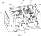
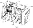
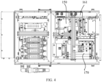
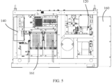
- 100 represents an accelerator
- 110 represents a magnetron
- 120 represents an accelerating tube
- 130 represents a microwave system
- 131 represents a circulator
- 132 represents a gas-filled straight waveguide
- 133 represents a gas-filled bending waveguide
- 134 represents a large water-cooled load
- 135 represents a small load
- 140 represents an electron gun power supply
- 150 represents a solid-state switch component
- 160 represents an external collimator
- 161 represents an external collimator control unit
- 170 represents a magnetic pulse transformer
- 180 represents a head rack.
- An embodiment of the present disclosure provides an X-band small-focus accelerator for non-destructive testing, including: a magnetron used to generate microwaves; an accelerating tube used to accelerate electrons, where the accelerating tube is an X-band accelerating tube; a microwave system connected between the magnetron and the accelerating tube, where the microwave system is used to feed the microwaves generated by the magnetron into the accelerating tube; an electron gun connected to the accelerating tube and used to emit an electron beam into the accelerating tube; and an electron gun power supply used to supply power to the electron gun; where the accelerating tube, the microwave system, the magnetron and the electron gun power supply are arranged in sequence in a front-rear direction of the accelerator to determine a length of the accelerator.
- the X-band accelerating tube by using the X-band accelerating tube, it is easy to achieve a small focus and a high image resolution. Since the X-band accelerating tube has a smaller volume than the S-band accelerating tube, the volume of the accelerating tube and its surrounding shielding may be reduced, and a weight of the accelerator may be reduced.
- the accelerating tube, the microwave system, the magnetron and the electron gun power supply required by the accelerator are arranged in sequence to define the length of the accelerator, so that an internal space of the accelerator may be fully utilized and an overall dimension of the accelerator may be reduced, thereby providing an electron linear acceleration device with a small focus, a small weight and a compact structure to meet application requirements in fields such as security inspection and non-destructive testing using an accelerator as a radiation source.
- FIG. 1 shows a schematic diagram of a three-dimensional structure of an X-band small-focus accelerator for non-destructive testing according to an embodiment of the present disclosure.
- FIG. 2 shows a schematic diagram of the three-dimensional structure of the X-band small-focus accelerator for non-destructive testing from another perspective according to an embodiment of the present disclosure, in which an external collimator control unit is hidden.
- FIG. 3 shows a schematic front view of an X-band small-focus accelerator for non-destructive testing according to an embodiment of the present disclosure.
- FIG. 4 shows a schematic top view of an X-band small-focus accelerator for non-destructive testing according to an embodiment of the present disclosure.
- FIG. 1 shows a schematic diagram of a three-dimensional structure of an X-band small-focus accelerator for non-destructive testing according to an embodiment of the present disclosure.
- FIG. 2 shows a schematic diagram of the three-dimensional structure of the X-band small-focus accelerator for non-destructive testing from another perspective according to an
- FIG. 5 shows a schematic rear view of an X-band small-focus accelerator for non-destructive testing according to an embodiment of the present disclosure.
- FIG. 6 shows a schematic left view of an X-band small-focus accelerator for non-destructive testing according to an embodiment of the present disclosure.
- FIG. 7 shows a schematic right view of an X-band small-focus accelerator for non-destructive testing according to an embodiment of the present disclosure.
- an X-band small-focus accelerator 100 for non-destructive testing may include at least a magnetron 110, an accelerating tube 120, a microwave system 130, an electron gun, and an electron gun power supply 140.
- the magnetron 110 is used as a microwave source for receiving high voltage pulses to generate microwaves and transmitting the microwaves to the accelerating tube 120.
- the accelerating tube 120 has a plurality of accelerating cavities. An electron beam may be accelerated and focused when passing through the accelerating cavities, so as to achieve an electron acceleration.
- the accelerating tube 120 is an X-band accelerating tube. Compared with existing S-band accelerating tubes, the X-band accelerating tube has a smaller volume in a case of achieving the same electron beam energy because a microwave frequency of X-band is higher. Accordingly, a shielding around the accelerating tube 120 has a smaller volume, and a weight of the accelerating tube 120 is reduced.
- the X-band accelerating tube needs to be provided with more accelerating cavities, and the electron beam may be accelerated and focused when passing through each cavity. Since the number of accelerating cavities of the X-band accelerating tube is greater than that of the S-band accelerating tube, a design flexibility of the X-band accelerating tube in electron bunching design is significantly better than that of the S-band accelerating tube, and it is easier to achieve a small focus.
- the microwave system 130 is connected between the magnetron 110 and the accelerating tube 120.
- the microwave system 130 is used to feed the microwaves generated by the magnetron 110 into the accelerating tube 120, that is, the microwave system 130 is used to transmit a microwave power generated by the magnetron 110 to the accelerating tube 120.
- the electron gun is connected to the accelerating tube 120 and is used to emit an electron beam into the accelerating tube 120, so that the electron beam may be accelerated and focused by using the accelerating tube 120.
- the electron gun power supply 140 is electrically connected to the electron gun and is used to supply power to the electron gun.
- the accelerating tube 120, the microwave system 130, the magnetron 110 and the electron gun power supply 140 are arranged in sequence in a front-rear direction of the accelerator 100 to determine a length of the accelerator 100.
- the front-rear direction of the accelerator 100 is parallel to a ray emission direction of the accelerator 100, and a left-right direction of the accelerator 100 is perpendicular to the ray emission direction of the accelerator 100, which will not be repeated later.
- the accelerating tube 120 is an X-band accelerating tube 120, which may easier achieve a small focus and a higher image resolution.
- the volume of the X-band accelerating tube 120 is smaller than that of the S-band accelerating tube, the volume and weight of the accelerating tube 120 and its shielding may be reduced accordingly.
- the accelerating tube 120, the microwave system 130, the magnetron 110 and the electron gun power supply 140 are closely arranged in the front-rear direction of the accelerator 100 to determine the length of the accelerator 120, so that the overall dimension of the accelerator 100 may be minimized.
- embodiments of the present disclosure may provide an X-band electron linear accelerator with a focal size of no more than 0.5 mm, a small weight and a compact structure that may generate electron energy of more than 1.95 MeV, which may meet the non-destructive testing needs of a large high-precision machined part in a case of limited space.
- FIG. 8 shows a schematic diagram of a three-dimensional structure of a magnetron and a microwave system according to an embodiment of the present disclosure.
- FIG. 9 shows a schematic front view of a magnetron and a microwave system according to an embodiment of the present disclosure.
- the microwave system 130 includes a waveguide and a circulator 131.
- the waveguide is used to transmit the microwave power
- the circulator 131 is used to isolate the microwave power fed back to the magnetron 110.
- the waveguide connects the magnetron 110 and the accelerating tube 120, and is used to transmit the microwave power generated by the magnetron 110 to the accelerating tube 120.
- the circulator 131 is arranged between the magnetron 110 and the accelerating tube 120.
- the circulator 131 is connected to the waveguide to form a microwave power transmission channel. Under an isolation effect of the circulator 131, the microwave power may be prevented from being fed back to the magnetron 110.
- the waveguide includes a gas-filled straight waveguide 132 and a gas-filled bending waveguide 133.
- the gas-filled straight waveguide 132 is connected between the magnetron 110 and the circulator 131
- the gas-filled bending waveguide 133 is connected between the circulator 131 and the accelerating tube 120.
- the magnetron 110 serves as a microwave power source, and may be an X-band coaxial magnetron.
- the microwave power generated by the magnetron 110 is fed into the accelerating tube 120 through the waveguide and the circulator 131.
- the waveguide only includes a gas-filled straight waveguide 132 and a gas-filled bending waveguide 133.
- the gas-filled straight waveguide 132 connects the magnetron 110 and the circulator 131
- the gas-filled bending waveguide 133 connects the circulator 131 and the accelerating tube 120. That is, the magnetron 110, the gas-filled straight waveguide 132, the circulator 131 and the gas-filled bending waveguide 133 are arranged in sequence in the front-rear direction of the accelerator 100. Therefore, it is possible to minimize a space occupied by the waveguide without affecting the microwave transmission between the magnetron 110, the circulator 131 and the accelerating tube 120, which may help reduce the dimension of the accelerator 100.
- the circulator 131 includes a four-port circulator, which is arranged in the front-rear direction of the accelerator 100.
- the four-port circulator mainly plays the role of directional power transmission and isolation protection in the accelerator 100.
- the microwave power output by the magnetron 110 is fed into port 1 of the four-port circulator and directionally transmitted to the accelerating tube 120 at port 2, and the microwave reflected back from the accelerating tube 120 is directionally transmitted to a large water-cooled load 134 at port 3 for absorption.
- the microwave power reflected by the large water-cooled load 134 may be absorbed by a small load 135 at port 4.
- the microwave power reflected by port 4 is very low, and may not affect a normal operation even if it returns to the magnetron 110 at port 1, so that the magnetron 110 may be protected.
- the four-port circulator is a differential phase-shift circulator 131, which consists of three parts, namely a magic T, a ⁇ /2 differential phase shifter and a 3dB narrow-side crack bridge.
- a connecting portion between the magic T, the ⁇ /2 differential phase shifter and the bridge is compressed as much as possible while ensuring a certain degree of isolation, thereby achieving a miniaturized four-port circulator.
- a length of the four-port circulator is reduced by about 1/3 compared with the original length while ensuring a 30 dB isolation, so that an overall length of the accelerator 100 may be reduced, and the accelerator 100 may be miniaturized.
- the circulator 131 may not be limited to a four-port circulator.
- the circulator 131 may also be a three-port circulator.
- the accelerator 100 further includes a gas filling system for supplying gas to the waveguide.
- the gas filling system may include a sulfur hexafluoride gas cylinder, a flow meter, a pipeline, a valve, etc., and the gas filling system may be placed in a gap inside the accelerator 100.
- the accelerator 100 further includes a modulator and a solid-state switch component 150.
- the solid-state switch component 150 includes eight charging and discharging modules, which are used to convert an input direct-current high voltage into a pulsed high voltage.
- the solid-state switch component 150 is connected to the magnetron 110.
- the magnetron 110 may receive the pulsed high voltage of the solid-state switch component 150 to generate microwaves.
- the modulator may be a lightweight solid-state modulator, which is mainly used to provide a high-voltage power supply, a low-voltage power supply and a timing control required by the accelerator 100.
- the solid-state switch component 150 is arranged inside the accelerator 100. Specifically, when the accelerator 100 is installed, the solid-state switch component 150 is located at a bottom of the magnetron 110, and is used to form a pulsed high voltage that is provided to the magnetron 110 to generate microwaves.
- the solid-state switch component 150 is a device that converts a direct-current high voltage into a pulse high voltage based on a principle of MARX generator. When a trigger signal has not yet arrived, the direct-current high voltage charges each energy storage capacitor in parallel. When the trigger signal is received, all the energy storage capacitors instantly discharge to the load in series.
- a structure of the solid-state switch component 150 may be compressed because the magnetron 110 is an X-band magnetron and an operating voltage of the X-band magnetron is lower than that of the S-band magnetron.
- a common solid-state switch component 150 includes a plurality of charging and discharging modules. In such embodiments, the number of charging and discharging modules may be appropriately reduced while meeting the operating voltage requirements of the X-band magnetron. Accordingly, an overall dimension of the solid-state switch component 150 may also be reduced, that is, a space occupied by the solid-state switch component 150 may be reduced, so that the internal structure of the accelerator 100 is more compact.
- the accelerator 100 further includes an external collimator 160 and an external collimator control unit 161.
- the external collimator 160 is arranged on a side of the accelerator 100 where the rays are emitted, and is located outside the accelerator 100.
- the external collimator 160 is used to collimate the emitted rays of the accelerator 100. It may be understood that providing the external collimator 160 is equivalent to extending the length of the accelerator 100.
- the external collimator 160 is separated from the external collimator control unit 161.
- the external collimator control unit 161 is arranged inside the accelerator 100 and electrically connected to the external collimator 160 to control the external collimator 160 to adjust an irradiation field.
- the external collimator control unit 161 is located at a bottom of the magnetron 110, which may minimize an impact on the length of the accelerator 100.
- the accelerator 100 further includes a magnetic pulse transformer 170, which connects the solid-state switch component 150 and the magnetron 110.
- the high-voltage pulse generated by the solid-state switch component 150 may be converted into a suitable pulse by the magnetic pulse transformer 170 and then supplied to the magnetron 110 serving as a microwave source.
- the magnetron 110 After receiving the high voltage pulse, the magnetron 110 outputs microwaves in the form of pulses, and the microwaves are transmitted to the accelerating tube 120 through the microwave system 130.
- the magnetic pulse transformer 170 and the solid-state switch component 150 have relatively large volume, if the magnetic pulse transformer 170 and the solid-state switch component 150 are arranged in the front-rear direction of the accelerator 100 according to an existing design, the accelerator 100 may have a too large length and a too large overall dimension. Therefore, in embodiments of the present disclosure, the magnetic pulse transformer 170 and the solid-state switch component 150 are arranged in the left-right direction of the accelerator 100. Since the accelerating tube 120 and its shielding have a particular width, an overall width of the accelerator 100 may not increase too much even if the magnetic pulse transformer 170 and the solid-state switch component 150 are arranged side by side. As shown in FIG. 1 , FIG. 2 , FIG. 4 and FIG.
- the magnetic pulse transformer 170, the solid-state switch component 150 and the external collimator control unit 161 are all located below the magnetron 110.
- the magnetic pulse transformer 170, the solid-state switch component 150 and the external collimator control unit 161 are arranged in sequence in the left-right direction of the accelerator 100 to determine the width of the accelerator 100.
- the accelerating tube 120 and its shielding may be normally accommodated inside the accelerator 100 without causing too large length and width of the accelerator 100.
- the electron gun power supply 140 includes an electron gun low-voltage power supply and an electron gun high-voltage power supply.
- the electron gun is a core component for generating electrons, which is welded together with a tube body of the accelerating tube 120 and is located in a vacuum environment. In operation, it is needed to heat a gun filament, and a gun cathode emits electrons to form an electron cloud after being heated. When emitting the beam, it is needed to apply a high voltage to the electron gun, so that the electrons are accelerated and injected into a first accelerating cavity of the accelerating tube 120.
- a common accelerator is provided with a gun high-voltage power supply, a high-voltage line, a pulse transformer and an electron gun filament power supply, these supporting components are installed at scattered positions, and the space in the accelerator 100 is wasted.
- low voltage, high voltage and boost functions of the electron gun are integrated into one power supply to form the electron gun power supply 140, which saves a lot of space and makes the structure of the accelerator 100 more compact.
- the electron gun power supply 140 is arranged in the front-rear direction of the accelerator 100 in embodiments of the present disclosure in order to avoid interference between the electron gun power supply 140 and other components in the accelerator 100, such as the magnetron 110 and the accelerating tube 120. In this way, the electron gun power supply 140 may not affect a normal installation of other components, and the accelerator 100 may not have a too large overall dimension.
- the accelerator 100 further includes a head rack 180, which has a frame structure.
- the head rack 180 forms an outer contour of the accelerator 100
- the external collimator 160 is arranged outside the head rack 180
- other components of the accelerator 100 are arranged inside the head rack 180.
- the accelerating tube 120, the microwave system 130, the magnetron 110 and the electron gun power supply 140 are all arranged inside the frame structure and distributed in a length direction of the frame structure, that is, arranged in sequence in the front-rear direction of the accelerator 100 to determine a length of the head rack 180;
- the magnetic pulse transformer 170, the solid-state switch component 150 and the external collimator control unit 161 are all arranged inside the frame structure and distributed in a width direction of the frame structure, that is, arranged in sequence in the left-right direction of the accelerator 100 to determine a width of the head rack 180; and the remaining components such as the gas filling system may be arranged in a remaining space in the frame structure of the head rack 180.
- the overall dimension including the length and the width of the head rack 180 may be limited and the space inside the head rack 180 may be fully utilized while ensuring that the accelerator 100 may achieve a small focus.
- the X-band small-focus accelerator for non-destructive testing has at least one of the following technical effects.
Landscapes
- Physics & Mathematics (AREA)
- Engineering & Computer Science (AREA)
- Plasma & Fusion (AREA)
- Spectroscopy & Molecular Physics (AREA)
- Health & Medical Sciences (AREA)
- Life Sciences & Earth Sciences (AREA)
- Chemical & Material Sciences (AREA)
- Analytical Chemistry (AREA)
- Biochemistry (AREA)
- General Health & Medical Sciences (AREA)
- General Physics & Mathematics (AREA)
- Immunology (AREA)
- Pathology (AREA)
- Particle Accelerators (AREA)
Applications Claiming Priority (2)
| Application Number | Priority Date | Filing Date | Title |
|---|---|---|---|
| CN202210775367.5A CN114980475A (zh) | 2022-07-01 | 2022-07-01 | 用于无损检测的x波段小焦点加速器 |
| PCT/CN2023/104644 WO2024002341A1 (zh) | 2022-07-01 | 2023-06-30 | 用于无损检测的x波段小焦点加速器 |
Publications (1)
| Publication Number | Publication Date |
|---|---|
| EP4550942A1 true EP4550942A1 (de) | 2025-05-07 |
Family
ID=82967395
Family Applications (1)
| Application Number | Title | Priority Date | Filing Date |
|---|---|---|---|
| EP23830504.9A Withdrawn EP4550942A1 (de) | 2022-07-01 | 2023-06-30 | X-band-beschleuniger mit kleinem brennfleck für zerstörungsfreie prüfung |
Country Status (4)
| Country | Link |
|---|---|
| US (1) | US20250227835A1 (de) |
| EP (1) | EP4550942A1 (de) |
| CN (1) | CN114980475A (de) |
| WO (1) | WO2024002341A1 (de) |
Families Citing this family (3)
| Publication number | Priority date | Publication date | Assignee | Title |
|---|---|---|---|---|
| CN114980475A (zh) * | 2022-07-01 | 2022-08-30 | 同方威视技术股份有限公司 | 用于无损检测的x波段小焦点加速器 |
| CN116113134A (zh) * | 2023-03-28 | 2023-05-12 | 北京机械工业自动化研究所有限公司 | 一种用于小型轻量化x波段电子直线加速器微波系统 |
| CN116261251A (zh) * | 2023-03-28 | 2023-06-13 | 北京机械工业自动化研究所有限公司 | 一种轻量化x波段无损检测用电子直线加速器 |
Family Cites Families (11)
| Publication number | Priority date | Publication date | Assignee | Title |
|---|---|---|---|---|
| CA990404A (en) * | 1974-08-01 | 1976-06-01 | Stanley O. Schriber | Double pass linear accelerator operating in a standing wave mode |
| CN202077262U (zh) * | 2011-01-18 | 2011-12-14 | 北京机械工业自动化研究所 | 无损检测用驻波电子直线加速器装置 |
| CN104822221B (zh) * | 2015-05-14 | 2017-12-12 | 丹东市无损检测设备有限公司 | 驻波电子直线加速器 |
| CN205648169U (zh) * | 2016-04-18 | 2016-10-12 | 清华大学 | 一种医用电子直线加速器 |
| CN208509358U (zh) * | 2018-07-26 | 2019-02-15 | 中国人民解放军96630部队 | 一种微波功率传输系统及工业ct检测设备 |
| CN111068189B (zh) * | 2019-11-27 | 2025-03-11 | 广东清大创新研究院有限公司 | 一种医用加速器、剂量监测系统及其剂量监测方法 |
| CN113058167A (zh) * | 2021-03-26 | 2021-07-02 | 成都奕康真空电子技术有限责任公司 | 一种机器人放疗系统 |
| CN113722871B (zh) * | 2021-11-03 | 2021-12-31 | 华中科技大学 | 一种x波段行波加速管的结构参数优化方法 |
| CN217608030U (zh) * | 2022-07-01 | 2022-10-18 | 同方威视技术股份有限公司 | 用于无损检测的x波段小焦点加速器 |
| CN114980475A (zh) * | 2022-07-01 | 2022-08-30 | 同方威视技术股份有限公司 | 用于无损检测的x波段小焦点加速器 |
| CN119815670A (zh) * | 2025-01-03 | 2025-04-11 | 兰州大学 | 一种用于x射线术中放疗设备的电子直线加速器 |
-
2022
- 2022-07-01 CN CN202210775367.5A patent/CN114980475A/zh active Pending
-
2023
- 2023-06-30 US US18/879,244 patent/US20250227835A1/en active Pending
- 2023-06-30 WO PCT/CN2023/104644 patent/WO2024002341A1/zh not_active Ceased
- 2023-06-30 EP EP23830504.9A patent/EP4550942A1/de not_active Withdrawn
Also Published As
| Publication number | Publication date |
|---|---|
| WO2024002341A1 (zh) | 2024-01-04 |
| CN114980475A (zh) | 2022-08-30 |
| US20250227835A1 (en) | 2025-07-10 |
Similar Documents
| Publication | Publication Date | Title |
|---|---|---|
| EP4550942A1 (de) | X-band-beschleuniger mit kleinem brennfleck für zerstörungsfreie prüfung | |
| Belomestnykh et al. | An 8 GeV linac as the Booster replacement in the Fermilab power upgrade: a Snowmass 2021 white paper | |
| EP3427553B1 (de) | Hybrider stehender- ,wandernderwelle linearbeschleuniger zur erzeugung von beschleunigten geladenen teilchen oder strahlungsbündeln und verfahren mit demselben | |
| EP2750486B1 (de) | Stehwellen- Elektronenlinearbeschleuniger mit stufenlos einstellbarer Energie und Verfahren dafür | |
| EP4369869A1 (de) | Strahlerzeugungsvorrichtung und steuerungsverfahren dafür | |
| US20080100236A1 (en) | Multi-section particle accelerator with controlled beam current | |
| CN106455288A (zh) | 一种能量可调节电子直线加速器 | |
| CN217608030U (zh) | 用于无损检测的x波段小焦点加速器 | |
| CN116261251A (zh) | 一种轻量化x波段无损检测用电子直线加速器 | |
| Kutsaev et al. | Ku-band electron linac for battery-powered hand-portable 2-MeV X-ray generator | |
| US7724876B2 (en) | Multi-color X-ray generator | |
| US7491958B2 (en) | Radiographic inspection system for inspecting the contents of a container having dual injector and dual accelerating section | |
| US20210018649A1 (en) | Multi-ray-source accelerator and inspection method | |
| Kutsaev et al. | Man-portable linac-based X-ray sources for NDT and nuclear security applications | |
| Miller et al. | A novel compact and portable linear accelerator electron beam system | |
| Belomestnykh et al. | An 8 GeV linac as the Booster replacement in the Fermilab Power Upgrade | |
| Neuffer et al. | An 8 GeV linac as the Booster replacement in the Fermilab Power Upgrade | |
| Enomoto et al. | Focusing system of the KEK positron generator | |
| US20250332452A1 (en) | Radiofrequency apparatus for a radiotherapy system | |
| CN121751456A (zh) | 多能级射线发生器和辐射成像设备 | |
| US10910189B2 (en) | Portable accelerator based X-ray source for active interrogation systems | |
| Pirozhenko et al. | Complex for X-ray Inspection of Large Containers | |
| Davis et al. | Modern electron induction LINACs | |
| JP2011165543A (ja) | X線発生装置 | |
| JP2019215294A (ja) | 中性子発生装置及び中性子発生方法 |
Legal Events
| Date | Code | Title | Description |
|---|---|---|---|
| STAA | Information on the status of an ep patent application or granted ep patent |
Free format text: STATUS: THE INTERNATIONAL PUBLICATION HAS BEEN MADE |
|
| PUAI | Public reference made under article 153(3) epc to a published international application that has entered the european phase |
Free format text: ORIGINAL CODE: 0009012 |
|
| STAA | Information on the status of an ep patent application or granted ep patent |
Free format text: STATUS: REQUEST FOR EXAMINATION WAS MADE |
|
| 17P | Request for examination filed |
Effective date: 20241227 |
|
| AK | Designated contracting states |
Kind code of ref document: A1 Designated state(s): AL AT BE BG CH CY CZ DE DK EE ES FI FR GB GR HR HU IE IS IT LI LT LU LV MC ME MK MT NL NO PL PT RO RS SE SI SK SM TR |
|
| STAA | Information on the status of an ep patent application or granted ep patent |
Free format text: STATUS: THE APPLICATION HAS BEEN WITHDRAWN |
|
| 18W | Application withdrawn |
Effective date: 20250410 |