EP4552449A2 - Système de connexion - Google Patents
Système de connexion Download PDFInfo
- Publication number
- EP4552449A2 EP4552449A2 EP24208781.5A EP24208781A EP4552449A2 EP 4552449 A2 EP4552449 A2 EP 4552449A2 EP 24208781 A EP24208781 A EP 24208781A EP 4552449 A2 EP4552449 A2 EP 4552449A2
- Authority
- EP
- European Patent Office
- Prior art keywords
- drawbar
- coupling
- agricultural machine
- extension
- connection system
- Prior art date
- Legal status (The legal status is an assumption and is not a legal conclusion. Google has not performed a legal analysis and makes no representation as to the accuracy of the status listed.)
- Pending
Links
Images


Classifications
-
- A—HUMAN NECESSITIES
- A01—AGRICULTURE; FORESTRY; ANIMAL HUSBANDRY; HUNTING; TRAPPING; FISHING
- A01B—SOIL WORKING IN AGRICULTURE OR FORESTRY; PARTS, DETAILS, OR ACCESSORIES OF AGRICULTURAL MACHINES OR IMPLEMENTS, IN GENERAL
- A01B59/00—Devices specially adapted for connection between animals or tractors and agricultural machines or implements
- A01B59/04—Devices specially adapted for connection between animals or tractors and agricultural machines or implements for machines pulled or pushed by a tractor
- A01B59/042—Devices specially adapted for connection between animals or tractors and agricultural machines or implements for machines pulled or pushed by a tractor having pulling means arranged on the rear part of the tractor
- A01B59/043—Devices specially adapted for connection between animals or tractors and agricultural machines or implements for machines pulled or pushed by a tractor having pulling means arranged on the rear part of the tractor supported at three points, e.g. by quick-release couplings
-
- A—HUMAN NECESSITIES
- A01—AGRICULTURE; FORESTRY; ANIMAL HUSBANDRY; HUNTING; TRAPPING; FISHING
- A01B—SOIL WORKING IN AGRICULTURE OR FORESTRY; PARTS, DETAILS, OR ACCESSORIES OF AGRICULTURAL MACHINES OR IMPLEMENTS, IN GENERAL
- A01B59/00—Devices specially adapted for connection between animals or tractors and agricultural machines or implements
- A01B59/04—Devices specially adapted for connection between animals or tractors and agricultural machines or implements for machines pulled or pushed by a tractor
- A01B59/042—Devices specially adapted for connection between animals or tractors and agricultural machines or implements for machines pulled or pushed by a tractor having pulling means arranged on the rear part of the tractor
-
- A—HUMAN NECESSITIES
- A01—AGRICULTURE; FORESTRY; ANIMAL HUSBANDRY; HUNTING; TRAPPING; FISHING
- A01B—SOIL WORKING IN AGRICULTURE OR FORESTRY; PARTS, DETAILS, OR ACCESSORIES OF AGRICULTURAL MACHINES OR IMPLEMENTS, IN GENERAL
- A01B59/00—Devices specially adapted for connection between animals or tractors and agricultural machines or implements
- A01B59/002—Details, component parts
- A01B59/006—Latched hooks
-
- B—PERFORMING OPERATIONS; TRANSPORTING
- B60—VEHICLES IN GENERAL
- B60D—VEHICLE CONNECTIONS
- B60D1/00—Traction couplings; Hitches; Draw-gear; Towing devices
- B60D1/01—Traction couplings or hitches characterised by their type
- B60D1/02—Bolt or shackle-type couplings
-
- B—PERFORMING OPERATIONS; TRANSPORTING
- B60—VEHICLES IN GENERAL
- B60D—VEHICLE CONNECTIONS
- B60D1/00—Traction couplings; Hitches; Draw-gear; Towing devices
- B60D1/14—Draw-gear or towing devices characterised by their type
- B60D1/143—Draw-gear or towing devices characterised by their type characterised by the mounting of the draw-gear on the towed vehicle
-
- B—PERFORMING OPERATIONS; TRANSPORTING
- B60—VEHICLES IN GENERAL
- B60D—VEHICLE CONNECTIONS
- B60D1/00—Traction couplings; Hitches; Draw-gear; Towing devices
- B60D1/14—Draw-gear or towing devices characterised by their type
- B60D1/145—Draw-gear or towing devices characterised by their type consisting of an elongated single bar or tube
-
- B—PERFORMING OPERATIONS; TRANSPORTING
- B60—VEHICLES IN GENERAL
- B60D—VEHICLE CONNECTIONS
- B60D1/00—Traction couplings; Hitches; Draw-gear; Towing devices
- B60D1/24—Traction couplings; Hitches; Draw-gear; Towing devices characterised by arrangements for particular functions
- B60D1/26—Traction couplings; Hitches; Draw-gear; Towing devices characterised by arrangements for particular functions for remote control, e.g. for releasing
-
- B—PERFORMING OPERATIONS; TRANSPORTING
- B60—VEHICLES IN GENERAL
- B60D—VEHICLE CONNECTIONS
- B60D1/00—Traction couplings; Hitches; Draw-gear; Towing devices
- B60D2001/001—Traction couplings; Hitches; Draw-gear; Towing devices specially adapted for use on vehicles other than cars
- B60D2001/008—Traction couplings; Hitches; Draw-gear; Towing devices specially adapted for use on vehicles other than cars specially adapted for implements, e.g. towed tools
Definitions
- the present invention relates to a connection system according to the preamble of claim 1 and a method according to the preamble of claim 17.
- Agricultural machinery that is pulled by a tractor during field work, and self-propelled agricultural machinery that is controlled by a driver during field work have long been known. These machines can also be moved in the same way during transfer journeys or road journeys, i.e., on the way to or from the field, i.e., either pulled by the tractor or steered autonomously by the driver.
- the brakes are powered and controlled by the towing vehicle. Where available, this also applies to steerable axles of the towed agricultural machinery.
- autonomous agricultural machinery is increasingly being used. These have their own drive and steering and carry out field work independently, without control commands from a driver. Since these vehicles cannot carry out a transfer journey on the road autonomously, they must be loaded onto a low-loader, for example, which is complex and increases the costs of the entire operation.
- One possible alternative is to attach the agricultural machine to a towing vehicle for a transfer journey, similar to a trailer.
- the agricultural machine could, for example, be coupled to the towing vehicle via a drawbar, whereby any change in the position of the towing vehicle relative to the agricultural machine influences the drawbar angle or articulation angle of the drawbar, which could be detected by sensors and used to steer the agricultural machine.
- At least one axle could also be mechanically steered by the drawbar.
- a drawbar that remains permanently attached to the agricultural machine represents a significant hindrance during field use, as it is inevitably located in an area that could be used by a cultivation implement such as a plough, harrow, mower, etc.
- drawbar that can be freely pivoted and attached to both the towing vehicle and the agricultural machine, and then removed again after the road trip. After the road trip, the drawbar must be removed and stowed away, which requires additional effort. The same applies to reassembly for the next road trip. Furthermore, while the drawbar transmits tensile and compressive forces, it does not transmit any torque, so it cannot be used for forced steering, for example.
- the object of the invention is to provide an improved system with which an agricultural machine can be temporarily coupled to a towing vehicle for road travel.
- the agricultural machine can also be referred to as an agricultural work machine.
- it can be a harvesting machine such as a forage harvester, a combine harvester, a baler, or a loader wagon.
- it could also be, for example, a tedder, a plough, a fertilizer spreader, a slurry tanker, or the like.
- the agricultural machine is designed for field cultivation, for example, for plowing, fertilizing, mowing, tedding, harvesting crops, or the like.
- the agricultural machine can be designed for coupling various attachments, such as a plough, a tedder, a header. etc. In this case, the actual vehicle body of the agricultural machine may not be set up for any specific field cultivation.
- the agricultural machine may have coupling structures such as a three-point linkage, via which an attachment adapted to the respective field cultivation can be coupled.
- the agricultural machine is also set up for field cultivation in this case.
- the agricultural machine can be a trailer that is towed by a tractor during field cultivation.
- the agricultural machine preferably has its own drive system that drives it during field cultivation.
- the agricultural machine is particularly preferably designed as an autonomous vehicle that is set up to carry out field cultivation without control commands from a driver or operator.
- the agricultural machine it would also be conceivable for the agricultural machine to have a control station or a driver's cab and to be controlled by a driver if necessary.
- the towing vehicle can be an agricultural machine itself, but it can also be another vehicle, such as a truck.
- the towing vehicle is a motor vehicle with its own drive, but it could also be, for example, a trailer without its own drive that is itself towed. It can be a vehicle driven by a driver or an autonomous vehicle.
- the agricultural machine and/or the towing vehicle may be considered, in whole or in part, part of the connection system. However, preferably, at least the towing vehicle is not considered part of the connection system.
- connection system is designed to connect the agricultural machine to the towing vehicle.
- a temporary connection for road travel is provided.
- the connection is configured at least to transmit tensile and compressive forces between the towing vehicle and the agricultural machine.
- transverse forces and/or torques can also be transmitted.
- the support part is designed to support the towing vehicle.
- the support part is designed to be coupled to the towing vehicle, whereby the term "support” implies that the support part can transfer at least a predominant portion of the weight force acting on the drawbar unit to the towing vehicle, preferably the entire weight force.
- the support part is preferably connectable to the towing vehicle in such a way that torques acting on the drawbar unit are absorbed by the towing vehicle. Such torques therefore do not lead to pivoting or tilting of the support part.
- the support part is preferably designed to be connected to the towing vehicle at a plurality of points.
- a connection to a lifting gear of the towing vehicle can be provided, for example, to a three-point linkage.
- the support part is preferably rigid in itself, but could consist of a plurality of rigidly connected individual elements.
- the drawbar extension is at least indirectly connected to the support part. This means that it is either directly connected to the support part or via at least one additional intermediate element. It is pivotable relative to the support part, i.e., relative to the support part, about a front drawbar axis.
- the front drawbar axis preferably runs at least predominantly vertically, for example, at an angle of less than 20° to the direction of gravity or to a vertical axis of the towing vehicle, based on the intended coupled state of the drawbar unit.
- the term "front drawbar axis" should not be interpreted to mean that the connection system must necessarily have a rear drawbar axis. This pivotability allows the drawbar extension to be aligned in various horizontal directions relative to the support part and the towing vehicle.
- the drawbar extension can be at least predominantly straight. It is preferably elongated, i.e., it has a dimension (“length") that can be at least twice, at least five times, or at least ten times larger than the other dimensions ("width,""height”). It is preferably rigid in itself. In particular, it is designed to transfer tensile and compressive forces between the towing vehicle and the agricultural machine.
- At least one coupling element is arranged on the drawbar extension for at least indirect coupling to the agricultural machine.
- the coupling element can be part of the drawbar extension or connected to it. It can be a rigid or a movable connection.
- the at least one coupling element is designed to at least indirectly couple the drawbar extension, and thus the drawbar unit and the towing vehicle, to the agricultural machine.
- the coupling is preferably based at least partially on a positive connection. It can be provided directly with the agricultural machine or with an intermediate element that is itself coupled to the agricultural machine.
- connection system according to the invention thus enables a connection during road travel similar to a drawbar permanently connected to the agricultural machine.
- no drawbar is necessary on the agricultural machine side, as the connection is at least partially established by the pivoting drawbar extension.
- At least part of the connection system can be separated from the agricultural machine for field cultivation and can remain on the towing vehicle.
- the drawbar unit is still coupled and supported there via the support part and therefore does not need to be removed and stowed away.
- connection system comprises a drawbar element which is designed for an at least indirect connection to a frame of the agricultural machine which can be pivoted about a rear drawbar axis, wherein corresponding coupling elements are arranged on the drawbar arm and on the drawbar element, which coupling elements are designed to lock the drawbar arm and the drawbar element in a locking position at least to couple translationally when they are arranged in a coupling position relative to one another, wherein at least one coupling element is adjustable into a release position in order to release the drawbar arm from the drawbar element.
- the drawbar element is designed for an at least indirect connection to a frame of the agricultural machine, pivotable about a rear drawbar axis.
- a frame is generally rigid, although it can consist of a plurality of rigidly connected individual elements. It forms a mechanically stable base on which further components of the agricultural machine can be arranged.
- at least one front axle and one rear axle can be arranged on the frame.
- both axles are advantageously steerable.
- the drawbar element can have a pivot bearing or at least a receptacle for a pivot bearing, through which the pivotability relative to the frame is achieved. In the assembled state, it can be connected directly to the frame or to an intermediate element (e.g., the front axle), which in turn is connected to the frame.
- the drawbar element is rigidly connected to the intermediate element, while the intermediate element is pivotally connected to the frame.
- both elements can also be considered together as a "drawbar element" within the meaning of this embodiment.
- the rear drawbar axle also preferably runs at least predominantly vertically, for example at an angle of less than 20° to the direction of gravity or to a vertical axis of the agricultural machine, based on the state of the drawbar element connected to the frame. It is preferably provided that the drawbar element is permanently connected to the frame, either directly or indirectly.
- the frame of the agricultural machine or the agricultural machine as a whole can be regarded as part of the connection system.
- the drawbar element is pivotally connected to the frame of the agricultural machine about the rear drawbar axis.
- the drawbar element can be pivotally mounted on the frame about the rear drawbar axis.
- the drawbar element is preferably rigid in itself. It is also designed to transmit tensile and compressive forces between the towing vehicle and the agricultural machine.
- the drawbar element can be significantly shorter than the drawbar extension.
- a maximum dimension of the drawbar element can correspond to a maximum of 50% or a maximum of 30% of a maximum dimension of the drawbar extension.
- Corresponding coupling elements are arranged on the drawbar arm and the drawbar element, which are designed to at least translationally couple the drawbar arm and the drawbar element in a locking position when they are arranged in a coupling position relative to one another, wherein at least one coupling element is adjustable into a release position in order to release the drawbar arm from the drawbar element. At least one coupling element is arranged on the drawbar arm, and at least one coupling element corresponding thereto is arranged on the drawbar element. “Corresponding" means that these coupling elements are designed to interact with one another. The interaction serves to couple the drawbar arm and the drawbar element to one another.
- an at least partial rotational locking is provided, i.e., the number of rotational degrees of freedom is reduced to a maximum of two.
- the drawbar arm and the drawbar element can be pivoted relative to each other about a coupling pivot axis, which is defined by the Coupling elements can be defined.
- the coupling elements can be designed such that they do not form a tangential positive connection with respect to the coupling pivot axis in the locking position.
- the coupling pivot axis preferably runs at least partially horizontally. If a rotational degree of freedom is missing, the drawbar arm and drawbar element behave like a single rigid body. Even if the rotational degree of freedom is given, they together form a drawbar that connects the towing vehicle to the agricultural machine.
- This drawbar can be pivoted about the front drawbar axis on the one hand and the rear drawbar axis on the other. This preferably enables relative movements within the horizontal plane. If the coupling pivot axis runs at least partially horizontally, relative movements in the vertical direction are also possible. It goes without saying that the drawbar arm extends at least predominantly horizontally, at least when coupled. The same applies to the drawbar formed from the drawbar arm and drawbar element.
- At least one coupling element can be adjusted to a release position in order to detach the drawbar extension from the drawbar element.
- the corresponding coupling element can therefore be adjusted between the locking position and the release position, for example, it can be pivoted and/or moved.
- the connection between the drawbar extension and the drawbar element is therefore not permanent, but can be separated again if necessary. This can be done particularly with autonomous agricultural machinery after the end of the road journey.
- one part, preferably the larger part, of the connection system is separated from the agricultural machine and can remain on the towing vehicle.
- This part, namely the drawbar unit is still coupled and supported there via the support part and therefore does not need to be removed and stowed away.
- Another part, preferably the smaller part can remain on the agricultural machine.
- the corresponding drawbar element can be designed so small that it does not interfere with the use of a field tillage implement, for example. Nevertheless, torque could be transmitted via a drawbar element pivoted on the frame, allowing, for example, forced steering of an axle.
- the drawbar element may be mechanically connected to an element of the axle, for example via a tie rod to a steering knuckle.
- a preferred embodiment provides that at least one first stop coupling element is rigidly connected to the drawbar element and at least one second stop coupling element is rigidly connected to the drawbar extension and, in the coupling position, forms a positive connection with the at least one first coupling element, wherein at least one adjusting coupling element is adjustable between the locking position and the release position.
- at least one coupling element is rigidly connected to both the drawbar element and the drawbar extension, which coupling element is referred to as the (first or second) stop coupling element.
- the positive connection between the stop coupling elements can define the coupling position at least on one side, i.e., it can prevent movement beyond the coupling position.
- the tractive force between the towing vehicle and the agricultural machine is transmitted at least partially via the stop coupling elements.
- At least one adjusting coupling element is adjustably connected to the drawbar arm, and in the locking position, at least one first stop coupling element is positively received between an adjusting coupling element and a second stop coupling element.
- the adjustable adjusting coupling element is thus assigned to the drawbar unit, whereby the structure in the area of the drawbar element remains simple.
- a remote control of the adjusting coupling element on the drawbar arm which will be discussed below, can also be used. can be implemented more easily than on the drawbar element.
- the adjusting coupling element can, in particular, be pivotably connected to the drawbar extension, although translational adjustability would also be conceivable, for example, in the manner of a slider.
- the adjusting coupling element When the adjusting coupling element has reached the locking position, it positively encloses the second stop coupling element together with a first stop coupling element, whereby it is preferably locked at least translationally.
- the further stop coupling element can be in contact with both the adjusting coupling element and the first stop coupling element.
- the drawbar arm and the drawbar element can be guided into the coupling position in an at least partially horizontal coupling direction, wherein the stop coupling elements form a positive connection in the coupling position, at least in the coupling direction.
- the coupling device can be defined as the direction of movement of the drawbar arm relative to the drawbar element.
- the two elements can move into the coupling position without colliding with each other.
- the movement into the coupling position can be at least partially guided. This means that interacting guide structures can be arranged on the drawbar arm and the drawbar element.
- the first and second stop coupling elements form a positive connection with each other, which at least relates to the coupling device.
- the coupling device extends at least partially horizontally and can, in particular, extend at an angle of less than 20° to the horizontal plane.
- the positive engagement of the stop coupling elements can also transmit a tensile force between the drawbar extension and the drawbar element.
- connection system has stationary first guide surfaces opposite the drawbar element and stationary second guide surfaces opposite the drawbar arm, which define a clearance transverse to the coupling direction, wherein at least one guide surface is at least partially bevelled with respect to the coupling direction in such a way that the clearance decreases when approaching the coupling position.
- the first guide surfaces can be formed on the drawbar element itself or on a component that is stationary connected to it, for example a first stop coupling element.
- the second guide surfaces can be formed on the drawbar element itself or on a component that is stationary connected to it, for example a second stop coupling element. Through their dimensions and/or their arrangement relative to one another, the guide surfaces define a clearance transverse to the coupling direction.
- the clearance is zero.
- the clearance should be minimal, i.e., virtually zero, since the relative position of the drawbar element and the drawbar extension should be precisely defined.
- Pairs of guide surfaces can be provided, arranged opposite each other in a cheek-like manner. Alternatively, a single guide surface could be designed in the manner of a funnel, for example, conically.
- a locking mechanism is arranged on the drawbar extension, which has the at least one actuating coupling element and by means of which the at least one actuating coupling element can be remotely controlled.
- the locking mechanism has the actuating coupling element and additionally at least one element by means of which the remote control function is realized.
- Remote control means in the broadest sense that a user does not have to directly access the actuating coupling element. In terms of user-friendliness, it can already be a significant advantage if the user must access an area that is, for example, at least 1 m away from the adjustment coupling element. This distance allows the operator to perform the adjustment even if an attachment is attached to the agricultural machine that is positioned above the drawbar extension.
- the locking mechanism comprises a pivotally mounted operating lever on the drawbar arm, which is spaced apart from the at least one actuating coupling element and connected to it in a force-transmitting manner, in particular via at least one coupling rod.
- the at least one actuating coupling element can be adjusted between the release position and the locking position, for example, also pivotally.
- the force transmission could in principle be hydraulic.
- a mechanical force transmission is preferred.
- at least one coupling rod can be interposed between the operating lever and the actuating coupling element. It can be pivotally connected on both sides. If the actuating coupling element is also pivotable, the pivot axes involved form a quadrilateral.
- the at least one actuating coupling element is adjustable by the locking mechanism.
- the locking mechanism has at least one actuator, by means of which the corresponding adjustment is possible.
- the actuator which can be designed as a hydraulic cylinder, for example, can preferably be controlled from the tractor.
- a corresponding actuator could act on an operating lever mentioned above, but the locking mechanism could also be designed completely differently.
- At least one actuating coupling element is designed as a latching element, which is configured to be elastically deflected out of the locking position against a restoring force when approaching the coupling position and to return to the locking position following the restoring force when the coupling position is reached.
- the actuating coupling element can, for example, interact with a first stop coupling element and be deflected out of the locking position by this.
- the shape of the two elements can be coordinated such that the deflection ends when the coupling position is reached and the actuating coupling element returns to the locking position. This can be referred to as latching of the actuating coupling element.
- the drawbar extension extends horizontally far from the towing vehicle when the drawbar unit is coupled to it.
- the corresponding length of the drawbar extension is an advantage, as it ensures sufficient distance between the inside wheels of the towing vehicle and the agricultural machine, for example, when negotiating tight curves.
- the far-projecting drawbar extension on the towing vehicle represents a disadvantage, particularly with regard to possible participation in road traffic.
- the drawbar extension can be pivoted about an at least partially horizontal installation axis relative to the support part between a towing position and a setup position, wherein it can preferably be pivoted about the installation axis by means of an actuator.
- the towing position is normally an at least approximately horizontal position and corresponds to a position in which the drawbar extension is coupled to the drawbar element. is or at least can be coupled to.
- the setup position can in particular be an approximately vertical position. This means that the pivoting between the towing position and the setup position can take place through an angle of, for example, between 70° and 110°, in particular between 80° and 100°.
- the drawbar boom is in the setup position, the towing vehicle can easily take part in road traffic, depending on the design.
- the setup axis preferably runs horizontally, for example parallel to a transverse axis of the towing vehicle.
- an actuator This can be done, for example, by means of a hydraulic cylinder that can be controlled from the towing vehicle.
- the drawbar extension could be directly connected to the support section. However, this would make it difficult to achieve both pivoting about the front drawbar axis and pivoting about the erection axis.
- An advantageous embodiment provides for the drawbar unit to have a pivoting part pivotally connected to the support section about the front drawbar axis, to which the drawbar extension is pivotally connected about the erection axis. This means that the pivoting part can be pivoted together with the drawbar extension about the front drawbar axis.
- the drawbar extension can be pivoted relative to the pivoting part and the support section about the erection axis. Their orientation relative to the support section naturally depends on the current pivoting position of the pivoting part.
- the drawbar boom can be pivoted relative to the support part about a further pivot axis, which at least in some embodiments can be referred to as a pendulum pivot axis or a rolling pivot axis. It preferably runs at an angle of 80° to 100°, in particular 90°, to the erection axis. Furthermore, it preferably runs at an angle of between 70° and 100°, in particular 80° to 100°, to the horizontal plane, at least in the pulling position of the drawbar boom. Said pivot axis can run parallel to a longitudinal axis of the drawbar boom, in particular at least in the pulling position.
- This additional pivot axis can enable rotational relative movements about the The longitudinal axis of the towing vehicle and/or the longitudinal axis of the agricultural machine can be compensated for. This can also be referred to as rolling movement or movement around a rolling axis.
- the support section, the pivoting section, and/or the drawbar extension could be replaced by two parts that pivot relative to each other.
- the drawbar extension should be able to pivot freely around the front drawbar axis.
- the drawbar extension can be retained in a central position relative to the support section with respect to the front drawbar axis.
- the central position is preferably a position in which the drawbar extension is aligned parallel to the longitudinal axis of the towing vehicle.
- "Retainable" can specifically mean “lockable,” but it can also refer to elastic retention. In the latter case, external torques can cause deflection from the central position, but this is counteracted by a restoring torque that limits the deflection and ensures return to the central position.
- the drawbar extension can be aligned by adjusting the towing vehicle. This means that the steering and drive of the towing vehicle provide at least a sufficiently precise means of moving the drawbar extension into a desired position, for example, the coupling position. If the drawbar extension is connected to the support part via the above-mentioned pivoting part, in this embodiment the pivoting part can be retained relative to the support part, resulting in the retention of the drawbar extension relative to the front pivot axis.
- the drawbar extension can be guided into the central position by an actuator and/or can be retained in the central position by an actuator.
- At least one actuator is provided which guides the drawbar extension (or the pivoting part including the drawbar extension) from a position pivoted sideways, for example, into the central position.
- an actuator can be configured to retain the drawbar extension in the central position.
- a locking actuator for example a hydraulic locking cylinder, can move a locking element into a tangential Form-fit connection with a retaining structure.
- the locking actuator can be arranged on the drawbar arm or on the pivoting part, and the retaining structure on the support part.
- the reverse arrangement is also possible.
- the retaining structure could be formed by a curved track whose contour recedes radially to an area in which the locking element is arranged in the center position. If the locking element is pressed against the curved track, a torque results around the front drawbar axis, which guides the drawbar arm into the center position.
- the connection system can have at least one monitoring sensor configured to monitor an approach to the coupling position.
- the monitoring sensor can be used to monitor whether and, if so, how the coupling position is being approached.
- the data supplied by the monitoring sensor can either be made available to a user, for example, the driver of the towing vehicle, or it could also be used by an autonomous system that carries out the coupling process entirely or partially automatically.
- a monitoring sensor can be designed as a camera.
- the camera can be arranged on the drawbar unit, for example, on the support part or on the drawbar arm, but possibly also on the pivoting part, if present. An arrangement on the drawbar element is also conceivable.
- the monitoring sensor should detect an area in which at least one coupling element is arranged during the coupling process. When directly approaching the coupling position, all coupling elements can be arranged in this area. In the case of a camera, detecting the area naturally means that the area is in the camera's field of view.
- connection system comprises at least one coupling sensor configured to detect when the locking position has been reached and to send a locking signal to a control unit of the agricultural machine. Once the coupling position has been reached, reaching the locking position indicates the successful completion of the coupling process.
- the coupling sensor can be The locking position can be determined in different ways, possibly even contactlessly.
- One possibility is for the coupling sensor to be designed as a simple touch sensor or switch. It could be arranged on the first stop coupling element and activated when touched by the actuating coupling element. This would also ensure that it is not triggered when the actuating coupling element assumes the locking position but the drawbar arm and the drawbar element are not in the coupling position.
- various other arrangements for the coupling sensor are also possible.
- the coupling sensor can, for example, be connected to the control unit via a wire. It could also be connected to a wireless interface that sends the locking signal wirelessly to an interface assigned to the control unit.
- the control unit of the agricultural machine can receive the locking signal and use this to recognize that the agricultural machine is now coupled to the towing vehicle.
- the control unit of the agricultural machine can react in different ways. For example, it can output an acoustic, optical, or other signal via a corresponding interface to inform the user that the coupling process has been successful. It can also transmit information about the coupling process to the towing vehicle or a mobile device via an interface.
- the control unit can be configured to switch to a mode intended for road travel upon receipt of the locking signal.
- the control unit can make various settings on the agricultural machine. For example, it can switch to a delay steering mode in which a rear axle is deflected in the opposite direction to the front axle if the absolute value of a front axle deflection exceeds a threshold.
- control unit can also switch to a mode in which the front axle is forced to steer by the drawbar element.
- control unit can set an individual steering mode in which both the front and rear axles are steered individually.
- control unit can control steering actuators that are assigned to the axles.
- the object is further achieved by a method for connecting an agricultural machine to a towing vehicle, wherein a drawbar unit having a support part and a drawbar arm connected at least indirectly to the support part and pivotable relative thereto about a front drawbar axis is supported on the towing vehicle with the support part, and wherein at least one coupling element is arranged on the drawbar arm, by means of which the drawbar arm is at least indirectly coupled to the agricultural machine.
- a drawbar unit having a support part and a drawbar arm connected at least indirectly to the support part and pivotable relative thereto about a front drawbar axis is supported on the towing vehicle with the support part, and wherein at least one coupling element is arranged on the drawbar arm, by means of which the drawbar arm is at least indirectly coupled to the agricultural machine.
- the towing vehicle with the drawbar unit and the agricultural machine can approach one another until a coupling position is reached in which the drawbar arm is at least indirectly coupled to the agricultural machine.
- a drawbar element can be pivotable about a rear drawbar axis, at least indirectly connected to a frame of the agricultural machine, wherein corresponding coupling elements are arranged on the drawbar arm and on the drawbar element, wherein the drawbar arm and the drawbar element are arranged in a coupling position and are coupled at least translationally by means of the coupling elements, for which purpose at least one coupling element is adjusted from a release position for releasing the drawbar arm from the drawbar element into a locking position.
- At least one coupling element can be moved from the locking position to the release position, after which the drawbar unit and the drawbar element are moved out of the coupling position.
- the towing vehicle and/or the agricultural machine can be moved, in particular driven.
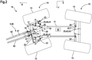
- Fig. 1 and 2 show bottom views of an agricultural machine 10, which in this example is designed as an autonomous vehicle.
- a longitudinal axis X, a transverse axis Y and a vertical axis Z of the agricultural machine 10 are shown, as well as a direction of travel R pointing opposite to the longitudinal axis X.
- various parts of the agricultural machine 10 have been omitted, in particular the majority of a vehicle body 12, which in Fig. 5 is indicated.
- a frame 11 can be seen, on which a steerable front axle 14 and a likewise steerable rear axle 15 are arranged, which is arranged behind the front axle 14 with respect to the direction of travel R.
- Both axles 14, 15 each have two wheels 13 arranged next to one another with respect to the transverse axis Y.
- Each axle 14, 15 has a steering knuckle, wherein a steering knuckle (not visible in the figures) of the respective wheel 13 is steered via tie rods 23, 24.
- Front axle tie rods 23 are coupled to a front axle steering cylinder (not shown for reasons of clarity), while rear axle tie rods 24 are coupled to a rear axle steering cylinder 43, more precisely to a steering cylinder piston rod 43.7 of the same.
- both axles 14, 15 are operated in an individual steering mode, whereby a control unit 45 can steer each of the axles 14, 15 independently of each other depending on the situation by means of the respective steering cylinders 43.
- a drawbar element 16 which can pivot about a first or rear drawbar axis A running parallel to the vertical axis Z. It is connected to one of the steering knuckles of the front axle 14 via an articulated drawbar tie rod 22.
- the agricultural machine 10 is operated in a deceleration steering mode.
- the front axle steering cylinder is switched to passive mode, and the steering of the front axle is determined entirely by the deflection of the drawbar element 16 due to the forced coupling via the drawbar tie rod 22.
- the drawbar element 16 has a release element 19 with two release fingers 20 projecting on both sides.
- Each release finger 20 is associated with a release cylinder 41, which leads to a release part 40 of a Transmission device 25.
- the transmission device 25 serves to transmit steering movements of the front axle 14 in a specific manner to the rear axle 15.
- Both release cylinders 41 are pivotally connected to the frame 11 about vertically extending release cylinder pivot axes D.
- the rear axle steering cylinder 43 forms a steering part 42 of the transmission device 25.
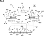
- Each trigger cylinder 41 comprises a cylinder body 41.1 having an end wall 41.2 at one end and also a partition wall 41.3.
- the partition wall 41.3 is traversed by a trigger cylinder piston rod 41.7 of a piston element 41.4.
- the piston element 41.4 also has two trigger cylinder piston parts 41.5, 41.6, which are rigidly connected by the trigger cylinder piston rod 41.7.
- a first trigger cylinder chamber 41.8 is formed between the partition wall 41.3 and the first trigger cylinder piston part 41.5, while a second trigger cylinder chamber 41.9 is formed between the partition wall 41.3 and the second trigger cylinder piston part 41.6.
- a third trigger cylinder chamber 41.10 is formed between the end wall 41.2 and the second trigger cylinder piston part 41.6.
- the third trigger cylinder chambers 41.10 are connected to a first hydraulic branch 26. In the deceleration steering mode, this branch is connected to a pressure accumulator 33 via a first valve 30 of a valve arrangement 29. This maintains a substantially constant hydraulic pressure in the third release cylinder chambers 41.10.
- the first release cylinder chamber 41.8 of the Fig. 3 and 4 left trigger cylinder 41 is connected via a second valve 31 to a second hydraulic branch 27, while the second trigger cylinder chamber 41.9 is connected via the second valve 31 to a third hydraulic branch 28.
- the first trigger cylinder chamber 41.8 of the Fig. 3 and 4 right trigger cylinder 41 is connected to the third hydraulic branch 28 via a third valve 32, while the second trigger cylinder chamber 41.9 is connected to the second hydraulic branch 27 via the third valve 31.
- the rear axle steering cylinder 43 has a cylinder body 43.1, which is bounded on both sides by end walls 43.2.
- the aforementioned steering cylinder piston rod 43.7 of a piston element 43.4 is passed through the end walls 43.2.
- the piston element 43.4 has a steering cylinder piston part 43.5 rigidly connected to the steering cylinder piston rod 43.7.
- a first steering cylinder chamber 43.8 and a second steering cylinder chamber 43.9 are defined between the latter and each of the end walls 43.2.
- the first steering cylinder chamber 43.8 is permanently connected to the second hydraulic branch 27, while the second steering cylinder chamber 43.9 is connected to the third hydraulic branch 28.
- Each of the trigger fingers 20 is designed to act on the piston element 41.4 of one of the trigger cylinders 41, more precisely to apply force to this on the side of the first trigger cylinder piston part 41.5.
- Fig. 1 shows a condition in which an absolute value of a front axle deflection of the front axle 14 is below a certain threshold value, which is particularly typical at high speeds, since the drawbar element 16 is usually only slightly deflected at these speeds.
- a front axle steering angle can be 8°, while the threshold value is 10°.
- Both release fingers 20 are out of contact with the release cylinders 41, which is why the rear axle 15 remains in its neutral position.
- Fig. 2 shows a state in which the absolute value of the front axle deflection is above the threshold value.
- the value of the front axle steering angle can be, for example, 17°.
- One of the release fingers 20 contacts the release cylinder 41 assigned to it and thus acts on the piston element 41.3 of the latter. As described above, this leads to a deflection of the piston element 43.3 of the rear axle steering cylinder 43, whereby the wheels 13 of the rear axle 15 are deflected in the opposite direction to the front axle 14 via the rear axle tie rods 24.
- Fig. 4 shows the transmission device in individual steering mode.
- the first hydraulic branch 26 is connected to a pressureless tank 34 via the first valve 29.
- the first trigger cylinder chamber 41.8 and the second trigger cylinder chamber 41.9 of the left trigger cylinder 41 are connected to each other via the second valve 31 and are simultaneously fluidically separated from the second hydraulic branch 27 and the third hydraulic branch 28.
- the first trigger cylinder chamber 41.8 and the second trigger cylinder chamber 41.9 of the right trigger cylinder 41 are connected to each other via the third valve 32 and are simultaneously fluidically separated from the second hydraulic branch 27 and the third hydraulic branch 28.
- the piston element 41.4 of each trigger cylinder 41 can be moved freely and there is no hydraulic power transmission to the rear axle steering cylinder 43. This can be Fig.
- each of the release cylinders 41 can be pivoted about the respective release cylinder pivot axis D pivoted so that it cannot be acted upon by the trigger element 19 in the single steering mode.
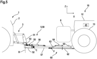
- the agricultural machine 10 is connected during road travel via the connection system 5 to the towing vehicle 1, which may be a tractor, for example.
- a three-point linkage 3 is arranged on the vehicle body 2 of the towing vehicle.
- the connection system 5 has a drawbar unit 50. The latter is coupled to the three-point linkage 3 by a support part 51 and supported thereon.
- a pivoting part 52 is pivotally connected to the support part 51 about a vertically extending second or front drawbar axis B.
- a drawbar extension 57 is connected to the pivoting part 52 about a horizontally extending installation axis C.
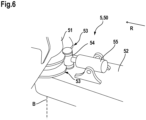
- a locking cylinder 55 is arranged on the pivoting part 52, by means of which a locking element 54 can be extended and retracted.
- Fig. 6 shows the locking element 54 in an extended position.
- the locking element 54 interacts with a curved track 53 fixedly attached to the support part 51. Its profile is designed such that extending the locking element 54 pivots the pivoting part 52, including the connected drawbar extension 57, into a central position and holds it there. This can mean complete locking or elastic retention. In the latter case, the pivoting part 52 can be deflected from the central position to a limited extent by an external torque against a restoring torque, but is returned to the central position in the absence of the external torque.
- the pivoting part 52 could also be actively pivotable about the front drawbar axis B by means of a corresponding actuator. Any position, in particular the central position, could then be set via the actuator.
- the drawbar extension 57 is connected to the pivoting part 52 by an erection cylinder 56.
- Fig. 5 shows the erection cylinder 56 in the extended position, with the drawbar extension 57 aligned approximately horizontally in a pulling position.
- the drawbar extension 57 can be pivoted into a not shown, approximately vertical erection position. This can be adjusted if the towing vehicle 1 is traveling on a road without the agricultural machine 10.
- the pivoting part 52 is also moved to the center position and retained there.
- the drawbar extension 57 can be pivoted relative to the support part 51 about a further pivot axis, which preferably runs at an angle of 80° to 100°, in particular 90°, to the installation axis C and which likewise preferably runs at an angle between 70° and 100°, in particular 80° to 100°, to the horizontal plane, at least in the towing position.
- Said pivot axis can, in particular, run parallel to the longitudinal axis of the drawbar extension 57, at least in the towing position. This could compensate for rotational relative movements about the longitudinal axis of the towing vehicle 1 and/or about the longitudinal axis X of the agricultural machine 10.
- the support part 51, the pivot part 52 and/or the drawbar extension 57 could be replaced by two parts that can pivot relative to one another.
- the drawbar unit 50 can be coupled to the drawbar element 16 via interacting coupling elements 18, 58, 61. Once the location of the agricultural machine has been reached, the drawbar unit 50 is decoupled and the agricultural machine 10 can carry out field work.
- a Fig. 5 highly schematically indicated attachment 8 can be used, which is preferably coupled to the vehicle body 12 even when driving on the road and is arranged comparatively close above the drawbar extension 57.
- a cylindrical first stop coupling element 18 is rigidly connected to the drawbar element 16.
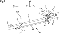
- the drawbar extension 57 has two hook-like second stop coupling elements 58 at its ends, which are designed to engage around the first stop coupling element 18 from behind when the drawbar extension 57 and the drawbar element 16 are in a Fig.7 and 8 shown coupling position to each other.
- the second stop coupling elements 58 are first placed behind the first stop coupling element 18.
- the drawbar extension 57 can first be pivoted slightly downwards relative to the horizontal by means of the erection cylinder 56, so that the second stop coupling elements 58 can be guided under the first stop coupling element 18 while the tractor 1 is reversing.
- the drawbar extension 57 is then pivoted into the horizontal position and the towing vehicle 1 can move forward, with the drawbar extension 57 with the second stop coupling elements 58 moving relative to the drawbar element 16 along a coupling direction K, which in this case runs antiparallel to the longitudinal axis X.
- the width of the drawbar element 16 is matched to the lateral distance between the second stop coupling elements 58 such that in the coupling position it is received between them with practically no play.
- the width of the drawbar element 16 increases with respect to the transverse axis Y along the coupling direction K, with first guide surfaces 17 extending obliquely relative to the coupling direction K being formed on both sides of the drawbar element 16, which interact with second guide surfaces 59 formed by the second stop coupling elements 58.
- a clearance defined between the guide surfaces 17, 59 decreases along the coupling direction until it is negligibly small in the coupling position. This provides a practically complete positive connection with respect to the transverse axis Y.
- the coupling between the drawbar unit 50 and the drawbar element 16 is completed by means of a locking mechanism 60.
- This has adjusting coupling elements 61 arranged on both sides outside the second stop coupling elements 58, which can be pivoted about a coupling element pivot axis E. They are connected via two coupling rods 62 to a rigid operating lever 63, which in turn is connected to the drawbar extension 57 so that it can pivot about an operating lever pivot axis F.
- Each coupling rod is rigid in itself and is pivotably connected on both sides.
- the first stop coupling element 18 is between the second stop coupling elements 58 and the adjusting coupling elements 61, i.e. there is a positive connection with respect to the longitudinal axis X, the transverse axis Y and the vertical axis Z.
- the connection is also rotationally secure with respect to the vertical axis Z, whereby pivoting movements from the drawbar unit are transmitted directly to the drawbar element 16.
- the drawbar arm 57 and the drawbar element 16 are thus locked against one another in a translational and partially rotational manner.
- a rotational degree of freedom is retained, since the drawbar arm 57 can pivot relative to the drawbar element 16 about a coupling pivot axis G, which runs horizontally through the first stop coupling element 18.
- the reaching of the locking position of the adjusting coupling elements 61 can be registered on the drawbar element 16 side by a coupling sensor (not shown), whereupon the control unit 45 of the agricultural machine 10 can automatically switch from the individual steering mode to the deceleration steering mode intended for road travel.
- the coupling rods 62 are designed so long that the operating lever 63 is arranged in front of the attachment 8 with respect to the longitudinal axis X. Accordingly, a user does not have to reach into the confined space below the attachment 8 to operate the operating lever 63.
- the length of each coupling rod 62 i.e. the distance between their pivot points, does not correspond to the distance of the coupling element pivot axis E from the operating lever pivot axis F, but is somewhat larger.
- pivoting of the operating lever 63 is only possible with slight deformation of the components involved, whereby Fig. 7 shown position and the one in Fig. 8 In the position shown, an unstable point results, which must be overcome by a corresponding torque. From this unstable point, the operating lever 63 returns to the nearest position without external forces. This ensures, on the one hand, that the locking mechanism 60 is guided into the locking position and, on the other hand, that it does not leave this position again without significant external forces.
- connection system 5 may have a camera 65 or another sensor by means of which a driver of the towing vehicle 1 can monitor the coupling process.
- Fig. 5 The camera is shown very schematically by a dashed line, where it is arranged, for example, on the drawbar boom 57, near the drawbar element 16. However, it could also be arranged, for example, on the pivoting part 52, on the support part 51 or even on the drawbar element 16. In the latter case, a wireless image transmission to the towing vehicle 1 could take place.
- an operating actuator 64 which in Fig. 5 is also shown in dashed lines and is attached to the drawbar extension 57 on the one hand and to the operating lever 63 on the other. In this case, it would of course also be possible to redesign the locking mechanism 60 entirely, for example, dispensing with the long coupling rods 62.
- the operating actuator 64 can advantageously be controlled from the tractor 1.
- the locking mechanism 60 can also have an actuating coupling element 61 designed as a latching element, which, when approaching the coupling position, is first elastically deflected by the first stop coupling element 18 from a rest position corresponding to the locking position and, when reaching the coupling position, returns to the rest position, establishing a positive connection with the first stop coupling element 18.
- an actuating coupling element 61 designed as a latching element, which, when approaching the coupling position, is first elastically deflected by the first stop coupling element 18 from a rest position corresponding to the locking position and, when reaching the coupling position, returns to the rest position, establishing a positive connection with the first stop coupling element 18.
- a further alternative, not shown, provides that the coupling direction K does not point forward, but backward in the direction of the longitudinal axis X, wherein the drawbar unit 50 can be brought into the coupling position by the towing vehicle 1 reversing towards the agricultural machine 10.
- guide surfaces bevelled relative to the coupling direction K could form a funnel through which the drawbar unit 50 with the at least one second stop coupling element 58 is guided, so to speak, automatically into the coupling position when reversing.
Landscapes
- Engineering & Computer Science (AREA)
- Mechanical Engineering (AREA)
- Life Sciences & Earth Sciences (AREA)
- Transportation (AREA)
- Zoology (AREA)
- Soil Sciences (AREA)
- Environmental Sciences (AREA)
- Agricultural Machines (AREA)
Applications Claiming Priority (1)
| Application Number | Priority Date | Filing Date | Title |
|---|---|---|---|
| DE102023131191.3A DE102023131191A1 (de) | 2023-11-09 | 2023-11-09 | Verbindungssystem |
Publications (2)
| Publication Number | Publication Date |
|---|---|
| EP4552449A2 true EP4552449A2 (fr) | 2025-05-14 |
| EP4552449A3 EP4552449A3 (fr) | 2025-09-03 |
Family
ID=93284579
Family Applications (1)
| Application Number | Title | Priority Date | Filing Date |
|---|---|---|---|
| EP24208781.5A Pending EP4552449A3 (fr) | 2023-11-09 | 2024-10-24 | Système de connexion |
Country Status (3)
| Country | Link |
|---|---|
| US (1) | US20250169387A1 (fr) |
| EP (1) | EP4552449A3 (fr) |
| DE (1) | DE102023131191A1 (fr) |
Family Cites Families (6)
| Publication number | Priority date | Publication date | Assignee | Title |
|---|---|---|---|---|
| DE8907918U1 (de) * | 1989-06-29 | 1990-10-31 | H. Niemeyer Söhne GmbH & Co KG, 4446 Hörstel | Landwirtschaftliches Anhängegerät |
| DE10257595B3 (de) * | 2002-12-09 | 2004-03-18 | Hans Sauermann | Anhängerkupplung für ein Fahrzeug |
| DE50309887D1 (de) * | 2003-10-07 | 2008-07-03 | Kurmann Technik Ag | Einrichtung für den Anbau einer landwirtschaftlichen Maschine |
| DE102008004318B4 (de) * | 2008-01-15 | 2016-07-28 | Amazonen-Werke H. Dreyer Gmbh & Co. Kg | Anhängevorrichtung |
| ITPD20120330A1 (it) * | 2012-11-06 | 2014-05-07 | Maschio Gaspardo Spa | Dispositivo di aggancio per attrezzature agricole trainate |
| US10899182B2 (en) * | 2017-08-15 | 2021-01-26 | Nathan Lasater | Tractor hitch |
-
2023
- 2023-11-09 DE DE102023131191.3A patent/DE102023131191A1/de active Pending
-
2024
- 2024-10-24 EP EP24208781.5A patent/EP4552449A3/fr active Pending
- 2024-11-06 US US18/938,312 patent/US20250169387A1/en active Pending
Also Published As
| Publication number | Publication date |
|---|---|
| EP4552449A3 (fr) | 2025-09-03 |
| DE102023131191A1 (de) | 2025-05-15 |
| US20250169387A1 (en) | 2025-05-29 |
Similar Documents
| Publication | Publication Date | Title |
|---|---|---|
| EP2621257B1 (fr) | Combinaison constituée d'un véhicule tracteur et d'un appareil | |
| EP0316896B1 (fr) | Machine de fenaison | |
| DE2948899A1 (de) | Fahrzeug mit geraete-schnellkuppler | |
| DE10120732A1 (de) | Anbauschnittstelle zwischen Arbeitsfahrzeug und Arbeitsgeräten sowie Steuereinrichtung | |
| EP2186713A2 (fr) | Dispositif de ballastage et véhicule agricole équipé avec ce dernier | |
| EP1466813B1 (fr) | Axe de dolly avec train de roues orientables | |
| EP1048195B1 (fr) | Dispositif de pivotement pour roues de support | |
| DE2707513C3 (de) | Rahmen für ein landwirtschaftliches Arbeitsgerät | |
| EP2269847B1 (fr) | Véhicule doté d'un axe à mouvement oscillant | |
| EP4101275B1 (fr) | Appareil accessoire destiné au traitement du sol | |
| EP3689119B1 (fr) | Outil de travail agricole, dispositif timon et combinaison de véhicule de traction et d'outil de travail | |
| EP3326844A1 (fr) | Raccordement de remorque de transport et train de remorque de transport dotés d'au moins deux tels raccordements de remorque de transport | |
| EP1859665B1 (fr) | Machine agricole tractée à grande largeur de travail | |
| DE3002354C2 (de) | Zug-und Lenkvorrichtung für einen Lastzug | |
| EP4552449A2 (fr) | Système de connexion | |
| EP4074156A1 (fr) | Dispositif timon pour une machine agricole tractée | |
| EP4272527A1 (fr) | Outil de montage pour l'usinage de champs | |
| DE29514980U1 (de) | Landwirtschaftliches Anhängegerät | |
| EP4555844A1 (fr) | Machine agricole | |
| DE3926381C1 (en) | Agricultural machine drive system - incorporates clutch with operating element connected to swivelling outer frame parts | |
| EP4101276B1 (fr) | Appareil accessoire destiné au traitement du sol | |
| EP1081021A2 (fr) | Remorque de véhicule à essieu dirigeable | |
| DE69907053T2 (de) | Bodenbearbeitungsmaschine mit seitlich aus-und einfaltbaren Werkzeugen | |
| DE3930078C2 (de) | Kurzkupplung | |
| EP4169370A1 (fr) | Appareil additionnel pour une machine agricole |
Legal Events
| Date | Code | Title | Description |
|---|---|---|---|
| PUAI | Public reference made under article 153(3) epc to a published international application that has entered the european phase |
Free format text: ORIGINAL CODE: 0009012 |
|
| STAA | Information on the status of an ep patent application or granted ep patent |
Free format text: STATUS: THE APPLICATION HAS BEEN PUBLISHED |
|
| AK | Designated contracting states |
Kind code of ref document: A2 Designated state(s): AL AT BE BG CH CY CZ DE DK EE ES FI FR GB GR HR HU IE IS IT LI LT LU LV MC ME MK MT NL NO PL PT RO RS SE SI SK SM TR |
|
| PUAL | Search report despatched |
Free format text: ORIGINAL CODE: 0009013 |
|
| AK | Designated contracting states |
Kind code of ref document: A3 Designated state(s): AL AT BE BG CH CY CZ DE DK EE ES FI FR GB GR HR HU IE IS IT LI LT LU LV MC ME MK MT NL NO PL PT RO RS SE SI SK SM TR |
|
| RIC1 | Information provided on ipc code assigned before grant |
Ipc: A01B 59/00 20060101AFI20250728BHEP Ipc: A01B 59/043 20060101ALI20250728BHEP Ipc: B60D 1/26 20060101ALI20250728BHEP |
|
| STAA | Information on the status of an ep patent application or granted ep patent |
Free format text: STATUS: REQUEST FOR EXAMINATION WAS MADE |
|
| 17P | Request for examination filed |
Effective date: 20260122 |