EP4552525A1 - Portémonnaie ou porténaie. ailette avec puce pour fonction de paiement et/ou de localisation - Google Patents
Portémonnaie ou porténaie. ailette avec puce pour fonction de paiement et/ou de localisation Download PDFInfo
- Publication number
- EP4552525A1 EP4552525A1 EP24178932.0A EP24178932A EP4552525A1 EP 4552525 A1 EP4552525 A1 EP 4552525A1 EP 24178932 A EP24178932 A EP 24178932A EP 4552525 A1 EP4552525 A1 EP 4552525A1
- Authority
- EP
- European Patent Office
- Prior art keywords
- chip
- wallet
- purse
- outer side
- payment
- Prior art date
- Legal status (The legal status is an assumption and is not a legal conclusion. Google has not performed a legal analysis and makes no representation as to the accuracy of the status listed.)
- Granted
Links
Images

Classifications
-
- A—HUMAN NECESSITIES
- A45—HAND OR TRAVELLING ARTICLES
- A45C—PURSES; LUGGAGE; HAND CARRIED BAGS
- A45C1/00—Purses; Money-bags; Wallets
- A45C1/06—Wallets; Notecases
-
- A—HUMAN NECESSITIES
- A45—HAND OR TRAVELLING ARTICLES
- A45C—PURSES; LUGGAGE; HAND CARRIED BAGS
- A45C1/00—Purses; Money-bags; Wallets
- A45C1/06—Wallets; Notecases
- A45C2001/065—Wallets; Notecases combined with card holders
Definitions
- the present invention relates to a purse or wallet with a payment chip according to the features in claim 1.
- Such wallets are also known as bifold or trifold wallets, meaning they can be folded out once or twice.
- the trend is increasingly shifting towards wallets that store cards inside the wallet, for example, with a hard case made of plastic or aluminum, into which several cards can be inserted. These cards can then be gradually ejected via a dispensing mechanism.
- the invention therefore has the object of providing a payment option that offers the consumer more security and at the same time more convenience than the prior art, and alternatively or additionally provides a location function for a corresponding purse or wallet.
- the purse or wallet has an exterior. This exterior is made of a flexible material, particularly leather. This leather material can be animal leather, synthetic leather, or even a microfiber material. Inside the purse or wallet, there is an interior space for cards and/or cash. There may be various card slots. The wallet may also contain a hard case for credit cards.
- a chip is now integrated into the outer wall, such that it can be used for wireless contact payment, for example, as a payment chip.
- a tracking chip which can also be called a tag or tracker.
- two chips can be used.
- a tracking chip and a payment chip can also be combined in a single chip, and this chip can be integrated into the outer wall accordingly.
- the chip is therefore an electronic component, which can also be referred to as an electrical circuit board.
- the chip is programmable within the meaning of the invention.
- the chip can also be referred to as a tracking chip or payment chip below. Both functions, i.e., tracking and payment, can also be fulfilled together by a single chip.
- the chip is incorporated into a leather or artificial leather or other flexible material on the outside in such a way that the chip is covered from the outside in relation to the environment, and is therefore covered or covered by the leather.
- the chip is preferably based on NFC or RFID technology; in particular, it is a passive chip.
- the chip is particularly formed from a microchip and antenna.
- the chip can also be referred to as a board or module.
- a battery can also be present to supply power to the chip and/or its antennas.
- the payment chip can be individually loaded by the user with a specific amount of currency, or a credit card can be mirrored onto the payment chip. If a user now wants to pay for an item on-site, for example, in a restaurant, bakery, or even a store, they simply pull out their wallet and hold the payment chip against the payment terminal, usually a card reader.
- the payment chip is programmed so that the predetermined currency is debited from the payment chip, similar to the function of an EC card or credit card.
- the key advantage of the present invention is that it is no longer necessary to remove individual cards or cash from the wallet's interior; instead, the wallet is simply held in front of the card reader or payment terminal. It does not even have to be opened. This is particularly evident More convenient for multiple individual payments, especially for smaller amounts. For example, when picking up a few rolls from a bakery every day, where you only need to pay a few euros, you don't have to take your credit card out of your wallet.
- the payment chip can be loaded with a predefined limit. Even if the payment chip were fraudulently read, the maximum amount debited will be the amount up to the limit, but not the entire amount, such as the balance on an EC card or the limit on a credit card.
- RFID protection is the flat incorporation of an RFID grid or RFID film into the outer shell or underneath the outer shell. This RFID grid or RFID film then surrounds the interior of the purse or wallet.
- RFID protection can also be the case, for example, made of a light metal, in which the credit cards are located. The chip is then located outside the case.
- the chip is a tracking chip, it is also located outside or above the RFID protection, and the tracking function is not restricted or disrupted by the RFID protection.
- the tracking chip also offers the advantage that a separate tracking device, such as an additional tag or tracker or even an additional tracking card, i.e. a credit card-sized tracking chip, is not required, since it is already present in the wallet.
- the chip can be charged with money, but in the case of a tracking chip, it can also be charged with electrical energy, for example, through inductive charging. While current battery technology allows for a tracking chip with a lifespan of two or three years, inductive charging can extend this lifespan even further.
- the outer skin is designed with a wall thickness of more than 1 mm, especially with a wall thickness of 1.5 mm to 5 mm and very particularly advantageously of 2 mm to 3 mm.
- the payment chip itself has a construction height of less than 3 mm, preferably less than 2 mm, preferably less than 1 mm and can thus be integrated seamlessly and almost invisibly, in particular without adding to the thickness of the outer skin.
- either the outer side or outer skin is designed as a single layer. This can then be cut at least partially along its plane. The resulting two parts of the outer skin, also referred to as skin flaps, are folded open, the payment chip is inserted and then glued and/or sewn together.
- the payment chip can be arranged between layers. Furthermore, a recess is particularly preferably provided in which the chip is arranged. Thus, increasing the wall thickness of the outer side is not necessary.
- the payment chip is then arranged almost invisibly beneath the outer side, at least away from visual access. Furthermore, if the interior of the wallet is filled, causing it to bulge outward, the payment chip would not be unnecessarily stretched or damaged due to tension. To this end, the payment chip is still positioned in the corner of the wallet, rather than centrally in the middle of the outer side.
- a logo, emblem, or pattern can be placed on the outside of the purse or wallet.
- the payment chip is then positioned in the wall directly below this logo. This provides the user with orientation and allows them to place the purse or wallet directly on the appropriate location on the payment terminal.
- the payment process This means that it is highly likely to always work on the first attempt, which increases user satisfaction.
- the chip is positioned relatively centrally. If the chip and/or a corresponding antenna has a corresponding dimension greater than 1 cm x 1 cm, the central position of the chip in the wallet positions it in such a way that a credit card is inserted, in particular, on the inside.
- the credit card provides the wallet with inherent stability in this area, reliably preventing accidental bending and thus damage to the chip or the antennas surrounding the chip.
- Figure 1 shows a purse or wallet 1, which has an outer side 2. This is a classic purse with an interior 3.
- the purse 1 is constructed from two foldable parts. Credit cards or cash (not shown in detail) are arranged in the interior 3.
- the outer side 2 is A payment chip 4 is now integrated, which is represented by a dashed line.
- the payment chip 4 is thus integrated into the outer side 2 and thus arranged below a surface 5 of the outer side.
- the payment chip 4 is arranged in an upper right corner relative to the image plane, i.e., in the area of a corner of the wallet.
- the payment chip 4 is arranged below a logo or coat of arms, thus a marking 6.
- the marking 6 is arranged in or on the surface 5 so that a user can easily locate the payment chip 4, thus increasing user-friendliness.
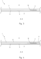
- FIG 3 now shows a cross section according to between the line AA from Figure 1
- the chip 4 is arranged beneath a surface 5 of the outside of the wallet.
- the outside 2 here is constructed in multiple layers with an outer layer 7.
- an RFID film or an RFID grid 8 is incorporated flatly.
- a lining 9 or an inner layer is incorporated in the region of an inner side.
- the chip 4 is now arranged beneath the surface 5, in particular in a space between the outer layer 7 and the lining 9.
- a recess 10 is particularly preferably arranged, with the chip 4 being within the recess 10. In particular, as can be clearly seen in the image, this also prevents any outward curvature of the outer layer 7, so that the chip 4 is not squeezed or clamped and is inevitably not visible from the outside.
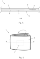
- Figure 4 shows an alternative design variant.
- the outer side 2 is formed as a single layer by an outer layer 7.
- the outer layer 7 itself has an incision 11 coming from one side and present in its longitudinal plane in order to arrange the chip 4 in an intermediate space or recess 10. After the chip 4 has been positioned, this incision 11 is again glued.
- an RFID film 8 is then arranged here too with respect to an interior space 3.
- an outer layer 2 in the form of a wax layer 12 or the like can optionally be applied to the outside.
- a lining 9 can again be arranged on an inner side.
- Figure 5 shows a further alternative design variant.
- an outer layer 7 is provided.
- the recess can, for example, be designed in the form of a specific milled recess, thus enabling optimal positioning of the chip 4.
- a stabilizing layer 13, for example, a hard case for credit cards (not shown in detail), can be arranged beneath the inner side of the lining 9.
- Figure 6 shows a design variant of a purse or wallet 1. It is a classic bifold wallet.
- the chip 4 is arranged centrally on one outer side 2. From the inner side 14, i.e. on the back of the chip 4 (not shown in detail here), it is possible to directly insert a credit card 15.
- This credit card 15 is thus arranged on the back of the chip 4 and gives the chip 4 its own stability, so that damage to or destruction of the chip 4 due to bending or kinking of the wallet is avoided as far as possible.
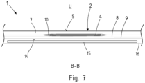
- the layer structure is in Figure 7 shown along section line BB.
- the outer side 2 in turn has an outer layer 7 with a surface 5.
- an RFID film or an RFID grid 8 is incorporated over a large area.
- the chip 4 is arranged below the surface 5, in particular in a recess 10 between the RFID film 8 and the outer layer 7, so that the overall wall thickness is not completely increased or thickened by the chip 4, but only to a justifiable extent.
- An inner lining or lining 9 is arranged below the RFID film 8.
- the individual layers can optionally be glued together.
- a pocket 16 for a credit card 15 is then shown directly on the inner side 14.
- the credit card 15 is thus located on the inner side 14 or on the back of the chip 4 and thereby provides the outer side 2, in which the chip 4 is mounted, with inherent stability, so that unintentional damage to the chip 4 is reliably avoided.
Landscapes
- Purses, Travelling Bags, Baskets, Or Suitcases (AREA)
Priority Applications (1)
| Application Number | Priority Date | Filing Date | Title |
|---|---|---|---|
| PCT/DE2024/100949 WO2025098570A1 (fr) | 2023-11-09 | 2024-11-08 | Porte-monnaie ou portefeuille ayant une puce pour fonction de paiement et/ou fonction de localisation |
Applications Claiming Priority (1)
| Application Number | Priority Date | Filing Date | Title |
|---|---|---|---|
| DE202023106571 | 2023-11-09 |
Publications (3)
| Publication Number | Publication Date |
|---|---|
| EP4552525A1 true EP4552525A1 (fr) | 2025-05-14 |
| EP4552525C0 EP4552525C0 (fr) | 2025-10-22 |
| EP4552525B1 EP4552525B1 (fr) | 2025-10-22 |
Family
ID=95398927
Family Applications (1)
| Application Number | Title | Priority Date | Filing Date |
|---|---|---|---|
| EP24178932.0A Active EP4552525B1 (fr) | 2023-11-09 | 2024-05-29 | Portemonnaie ou portefeuille avec une puce pour fonction de paiement et/ou de localisation |
Country Status (1)
| Country | Link |
|---|---|
| EP (1) | EP4552525B1 (fr) |
Citations (3)
| Publication number | Priority date | Publication date | Assignee | Title |
|---|---|---|---|---|
| CN205671679U (zh) * | 2016-06-17 | 2016-11-09 | 浪潮集团有限公司 | 一种物联网钱包 |
| CN111904123A (zh) * | 2019-05-10 | 2020-11-10 | 永惠企业有限公司 | 用于折叠式皮夹的防盗录及低射频信号隔离片 |
| EP4079183A1 (fr) * | 2021-04-23 | 2022-10-26 | PiNkey AG | Porte-monnaie ou portefeuille doté d'un logement pour une balise / un traqueur |
-
2024
- 2024-05-29 EP EP24178932.0A patent/EP4552525B1/fr active Active
Patent Citations (3)
| Publication number | Priority date | Publication date | Assignee | Title |
|---|---|---|---|---|
| CN205671679U (zh) * | 2016-06-17 | 2016-11-09 | 浪潮集团有限公司 | 一种物联网钱包 |
| CN111904123A (zh) * | 2019-05-10 | 2020-11-10 | 永惠企业有限公司 | 用于折叠式皮夹的防盗录及低射频信号隔离片 |
| EP4079183A1 (fr) * | 2021-04-23 | 2022-10-26 | PiNkey AG | Porte-monnaie ou portefeuille doté d'un logement pour une balise / un traqueur |
Also Published As
| Publication number | Publication date |
|---|---|
| EP4552525C0 (fr) | 2025-10-22 |
| EP4552525B1 (fr) | 2025-10-22 |
Similar Documents
| Publication | Publication Date | Title |
|---|---|---|
| DE60303565T2 (de) | Tragbares Informationsverarbeitungsgerät | |
| DE69818803T2 (de) | Kartenlesevorrichtung, ins besondere für ic karten | |
| WO2010097342A2 (fr) | Porte-monnaie ou portefeuille pouvant recevoir des cartes de crédit | |
| EP2685343A1 (fr) | Holder device for a mobile terminal | |
| EP4552525B1 (fr) | Portemonnaie ou portefeuille avec une puce pour fonction de paiement et/ou de localisation | |
| DE102006015782A1 (de) | Vorrichtung zur Speicherung und drahtlosen Übertragung von Daten | |
| DE102023124196A1 (de) | Kleines kartenetui mit ladefunktion | |
| WO2025098570A1 (fr) | Porte-monnaie ou portefeuille ayant une puce pour fonction de paiement et/ou fonction de localisation | |
| EP2756774B1 (fr) | Étui à coque dure | |
| DE202005013346U1 (de) | Ausweis-Schutzhülle | |
| DE19939956A1 (de) | Vorrichtung zum Datenaustausch zwischen einer Schreib-/Leseeinrichtung für kontaktbehaftete Chipkarten und einem kontaktlosen Datenträger | |
| DE102004027125A1 (de) | Sicherheitsdokument | |
| DE102013010389B4 (de) | Umhüllung für Kreditkarten und dergleichen | |
| DE102019101385B4 (de) | Geldbörse oder Brieftasche | |
| DE202017001139U1 (de) | Sicherheits-Multifunktionsbörse | |
| EP3560372A1 (fr) | Porte-monnaie | |
| AT515445B1 (de) | Schutzvorrichtung mit einer Aufnahme für mindestens eine Chipkarte | |
| DE19629085C2 (de) | Datenverarbeitungsvorrichtung zur Dokumentation und/oder zur Auswertung von Transaktionen eines Benutzers | |
| EP1159703B1 (fr) | Appareil d'introduction de donnees | |
| DE202025106119U1 (de) | Hülle für Kartenhalter | |
| DE29704071U1 (de) | Mappe, insbesondere Geldbörse oder Brieftasche | |
| DE202019002454U1 (de) | Kartenetui | |
| DE102019130049A1 (de) | Kartenetui | |
| DE69731239T2 (de) | Tragbare Vorrichtung für finanzbezogene Ferntransaktionen mit Mikroprozessorkarte | |
| EP3132388B1 (fr) | Appareil pour la prévention d'un vol de données, fraude d'identité et de payement lors d'une transmission sans contact de données par ondes électromagnétiques |
Legal Events
| Date | Code | Title | Description |
|---|---|---|---|
| PUAI | Public reference made under article 153(3) epc to a published international application that has entered the european phase |
Free format text: ORIGINAL CODE: 0009012 |
|
| STAA | Information on the status of an ep patent application or granted ep patent |
Free format text: STATUS: REQUEST FOR EXAMINATION WAS MADE |
|
| 17P | Request for examination filed |
Effective date: 20250409 |
|
| AK | Designated contracting states |
Kind code of ref document: A1 Designated state(s): AL AT BE BG CH CY CZ DE DK EE ES FI FR GB GR HR HU IE IS IT LI LT LU LV MC ME MK MT NL NO PL PT RO RS SE SI SK SM TR |
|
| GRAP | Despatch of communication of intention to grant a patent |
Free format text: ORIGINAL CODE: EPIDOSNIGR1 |
|
| STAA | Information on the status of an ep patent application or granted ep patent |
Free format text: STATUS: GRANT OF PATENT IS INTENDED |
|
| INTG | Intention to grant announced |
Effective date: 20250729 |
|
| GRAS | Grant fee paid |
Free format text: ORIGINAL CODE: EPIDOSNIGR3 |
|
| GRAA | (expected) grant |
Free format text: ORIGINAL CODE: 0009210 |
|
| STAA | Information on the status of an ep patent application or granted ep patent |
Free format text: STATUS: THE PATENT HAS BEEN GRANTED |
|
| AK | Designated contracting states |
Kind code of ref document: B1 Designated state(s): AL AT BE BG CH CY CZ DE DK EE ES FI FR GB GR HR HU IE IS IT LI LT LU LV MC ME MK MT NL NO PL PT RO RS SE SI SK SM TR |
|
| REG | Reference to a national code |
Ref country code: CH Ref legal event code: F10 Free format text: ST27 STATUS EVENT CODE: U-0-0-F10-F00 (AS PROVIDED BY THE NATIONAL OFFICE) Effective date: 20251022 Ref country code: GB Ref legal event code: FG4D Free format text: NOT ENGLISH |
|
| REG | Reference to a national code |
Ref country code: CH Ref legal event code: R17 Free format text: ST27 STATUS EVENT CODE: U-0-0-R10-R17 (AS PROVIDED BY THE NATIONAL OFFICE) Effective date: 20251027 |
|
| REG | Reference to a national code |
Ref country code: DE Ref legal event code: R096 Ref document number: 502024000319 Country of ref document: DE |
|
| REG | Reference to a national code |
Ref country code: IE Ref legal event code: FG4D Free format text: LANGUAGE OF EP DOCUMENT: GERMAN |
|
| U01 | Request for unitary effect filed |
Effective date: 20251107 |
|
| U07 | Unitary effect registered |
Designated state(s): AT BE BG DE DK EE FI FR IT LT LU LV MT NL PT RO SE SI Effective date: 20251113 |
|
| PG25 | Lapsed in a contracting state [announced via postgrant information from national office to epo] |
Ref country code: ES Free format text: LAPSE BECAUSE OF FAILURE TO SUBMIT A TRANSLATION OF THE DESCRIPTION OR TO PAY THE FEE WITHIN THE PRESCRIBED TIME-LIMIT Effective date: 20251022 |
|
| PG25 | Lapsed in a contracting state [announced via postgrant information from national office to epo] |
Ref country code: NO Free format text: LAPSE BECAUSE OF FAILURE TO SUBMIT A TRANSLATION OF THE DESCRIPTION OR TO PAY THE FEE WITHIN THE PRESCRIBED TIME-LIMIT Effective date: 20260122 |
|
| PG25 | Lapsed in a contracting state [announced via postgrant information from national office to epo] |
Ref country code: HR Free format text: LAPSE BECAUSE OF FAILURE TO SUBMIT A TRANSLATION OF THE DESCRIPTION OR TO PAY THE FEE WITHIN THE PRESCRIBED TIME-LIMIT Effective date: 20251022 |
|
| PG25 | Lapsed in a contracting state [announced via postgrant information from national office to epo] |
Ref country code: RS Free format text: LAPSE BECAUSE OF FAILURE TO SUBMIT A TRANSLATION OF THE DESCRIPTION OR TO PAY THE FEE WITHIN THE PRESCRIBED TIME-LIMIT Effective date: 20260122 |
|
| PG25 | Lapsed in a contracting state [announced via postgrant information from national office to epo] |
Ref country code: IS Free format text: LAPSE BECAUSE OF FAILURE TO SUBMIT A TRANSLATION OF THE DESCRIPTION OR TO PAY THE FEE WITHIN THE PRESCRIBED TIME-LIMIT Effective date: 20260222 |
|
| PG25 | Lapsed in a contracting state [announced via postgrant information from national office to epo] |
Ref country code: PL Free format text: LAPSE BECAUSE OF FAILURE TO SUBMIT A TRANSLATION OF THE DESCRIPTION OR TO PAY THE FEE WITHIN THE PRESCRIBED TIME-LIMIT Effective date: 20251022 |
|
| U20 | Renewal fee for the european patent with unitary effect paid |
Year of fee payment: 3 Effective date: 20260325 |