EP4552596A1 - Gesteuerte konstantstromsysteme, vorrichtungen, komponenten und verfahren zur navigation oder positionsbestimmung oder ortsbestimmung einer medizinischen vorrichtung im körper eines patienten - Google Patents
Gesteuerte konstantstromsysteme, vorrichtungen, komponenten und verfahren zur navigation oder positionsbestimmung oder ortsbestimmung einer medizinischen vorrichtung im körper eines patienten Download PDFInfo
- Publication number
- EP4552596A1 EP4552596A1 EP24211929.5A EP24211929A EP4552596A1 EP 4552596 A1 EP4552596 A1 EP 4552596A1 EP 24211929 A EP24211929 A EP 24211929A EP 4552596 A1 EP4552596 A1 EP 4552596A1
- Authority
- EP
- European Patent Office
- Prior art keywords
- catheter
- patient
- electrodes
- constant current
- body surface
- Prior art date
- Legal status (The legal status is an assumption and is not a legal conclusion. Google has not performed a legal analysis and makes no representation as to the accuracy of the status listed.)
- Pending
Links
Images






Classifications
-
- A—HUMAN NECESSITIES
- A61—MEDICAL OR VETERINARY SCIENCE; HYGIENE
- A61B—DIAGNOSIS; SURGERY; IDENTIFICATION
- A61B34/00—Computer-aided surgery; Manipulators or robots specially adapted for use in surgery
- A61B34/20—Surgical navigation systems; Devices for tracking or guiding surgical instruments, e.g. for frameless stereotaxis
-
- A—HUMAN NECESSITIES
- A61—MEDICAL OR VETERINARY SCIENCE; HYGIENE
- A61B—DIAGNOSIS; SURGERY; IDENTIFICATION
- A61B18/00—Surgical instruments, devices or methods for transferring non-mechanical forms of energy to or from the body
- A61B18/04—Surgical instruments, devices or methods for transferring non-mechanical forms of energy to or from the body by heating
- A61B18/12—Surgical instruments, devices or methods for transferring non-mechanical forms of energy to or from the body by heating by passing a current through the tissue to be heated, e.g. high-frequency current
- A61B18/14—Probes or electrodes therefor
- A61B18/1492—Probes or electrodes therefor having a flexible, catheter-like structure, e.g. for heart ablation
-
- A—HUMAN NECESSITIES
- A61—MEDICAL OR VETERINARY SCIENCE; HYGIENE
- A61B—DIAGNOSIS; SURGERY; IDENTIFICATION
- A61B34/00—Computer-aided surgery; Manipulators or robots specially adapted for use in surgery
- A61B34/10—Computer-aided planning, simulation or modelling of surgical operations
-
- A—HUMAN NECESSITIES
- A61—MEDICAL OR VETERINARY SCIENCE; HYGIENE
- A61B—DIAGNOSIS; SURGERY; IDENTIFICATION
- A61B5/00—Measuring for diagnostic purposes; Identification of persons
- A61B5/06—Devices, other than using radiation, for detecting or locating foreign bodies ; Determining position of diagnostic devices within or on the body of the patient
- A61B5/061—Determining position of a probe within the body employing means separate from the probe, e.g. sensing internal probe position employing impedance electrodes on the surface of the body
- A61B5/063—Determining position of a probe within the body employing means separate from the probe, e.g. sensing internal probe position employing impedance electrodes on the surface of the body using impedance measurements
-
- A—HUMAN NECESSITIES
- A61—MEDICAL OR VETERINARY SCIENCE; HYGIENE
- A61B—DIAGNOSIS; SURGERY; IDENTIFICATION
- A61B18/00—Surgical instruments, devices or methods for transferring non-mechanical forms of energy to or from the body
- A61B2018/00053—Mechanical features of the instrument of device
- A61B2018/00214—Expandable means emitting energy, e.g. by elements carried thereon
- A61B2018/00267—Expandable means emitting energy, e.g. by elements carried thereon having a basket shaped structure
-
- A—HUMAN NECESSITIES
- A61—MEDICAL OR VETERINARY SCIENCE; HYGIENE
- A61B—DIAGNOSIS; SURGERY; IDENTIFICATION
- A61B18/00—Surgical instruments, devices or methods for transferring non-mechanical forms of energy to or from the body
- A61B2018/00315—Surgical instruments, devices or methods for transferring non-mechanical forms of energy to or from the body for treatment of particular body parts
- A61B2018/00345—Vascular system
- A61B2018/00351—Heart
-
- A—HUMAN NECESSITIES
- A61—MEDICAL OR VETERINARY SCIENCE; HYGIENE
- A61B—DIAGNOSIS; SURGERY; IDENTIFICATION
- A61B18/00—Surgical instruments, devices or methods for transferring non-mechanical forms of energy to or from the body
- A61B2018/00571—Surgical instruments, devices or methods for transferring non-mechanical forms of energy to or from the body for achieving a particular surgical effect
- A61B2018/00577—Ablation
-
- A—HUMAN NECESSITIES
- A61—MEDICAL OR VETERINARY SCIENCE; HYGIENE
- A61B—DIAGNOSIS; SURGERY; IDENTIFICATION
- A61B18/00—Surgical instruments, devices or methods for transferring non-mechanical forms of energy to or from the body
- A61B2018/00636—Sensing and controlling the application of energy
- A61B2018/00773—Sensed parameters
- A61B2018/00839—Bioelectrical parameters, e.g. ECG, EEG
-
- A—HUMAN NECESSITIES
- A61—MEDICAL OR VETERINARY SCIENCE; HYGIENE
- A61B—DIAGNOSIS; SURGERY; IDENTIFICATION
- A61B34/00—Computer-aided surgery; Manipulators or robots specially adapted for use in surgery
- A61B34/10—Computer-aided planning, simulation or modelling of surgical operations
- A61B2034/101—Computer-aided simulation of surgical operations
- A61B2034/102—Modelling of surgical devices, implants or prosthesis
-
- A—HUMAN NECESSITIES
- A61—MEDICAL OR VETERINARY SCIENCE; HYGIENE
- A61B—DIAGNOSIS; SURGERY; IDENTIFICATION
- A61B34/00—Computer-aided surgery; Manipulators or robots specially adapted for use in surgery
- A61B34/10—Computer-aided planning, simulation or modelling of surgical operations
- A61B2034/101—Computer-aided simulation of surgical operations
- A61B2034/105—Modelling of the patient, e.g. for ligaments or bones
-
- A—HUMAN NECESSITIES
- A61—MEDICAL OR VETERINARY SCIENCE; HYGIENE
- A61B—DIAGNOSIS; SURGERY; IDENTIFICATION
- A61B34/00—Computer-aided surgery; Manipulators or robots specially adapted for use in surgery
- A61B34/10—Computer-aided planning, simulation or modelling of surgical operations
- A61B2034/107—Visualisation of planned trajectories or target regions
-
- A—HUMAN NECESSITIES
- A61—MEDICAL OR VETERINARY SCIENCE; HYGIENE
- A61B—DIAGNOSIS; SURGERY; IDENTIFICATION
- A61B34/00—Computer-aided surgery; Manipulators or robots specially adapted for use in surgery
- A61B34/20—Surgical navigation systems; Devices for tracking or guiding surgical instruments, e.g. for frameless stereotaxis
- A61B2034/2046—Tracking techniques
- A61B2034/2051—Electromagnetic tracking systems
-
- A—HUMAN NECESSITIES
- A61—MEDICAL OR VETERINARY SCIENCE; HYGIENE
- A61B—DIAGNOSIS; SURGERY; IDENTIFICATION
- A61B34/00—Computer-aided surgery; Manipulators or robots specially adapted for use in surgery
- A61B34/20—Surgical navigation systems; Devices for tracking or guiding surgical instruments, e.g. for frameless stereotaxis
- A61B2034/2046—Tracking techniques
- A61B2034/2051—Electromagnetic tracking systems
- A61B2034/2053—Tracking an applied voltage gradient
-
- A—HUMAN NECESSITIES
- A61—MEDICAL OR VETERINARY SCIENCE; HYGIENE
- A61B—DIAGNOSIS; SURGERY; IDENTIFICATION
- A61B34/00—Computer-aided surgery; Manipulators or robots specially adapted for use in surgery
- A61B34/20—Surgical navigation systems; Devices for tracking or guiding surgical instruments, e.g. for frameless stereotaxis
- A61B2034/2046—Tracking techniques
- A61B2034/2055—Optical tracking systems
-
- A—HUMAN NECESSITIES
- A61—MEDICAL OR VETERINARY SCIENCE; HYGIENE
- A61B—DIAGNOSIS; SURGERY; IDENTIFICATION
- A61B34/00—Computer-aided surgery; Manipulators or robots specially adapted for use in surgery
- A61B34/20—Surgical navigation systems; Devices for tracking or guiding surgical instruments, e.g. for frameless stereotaxis
- A61B2034/2046—Tracking techniques
- A61B2034/2065—Tracking using image or pattern recognition
-
- A—HUMAN NECESSITIES
- A61—MEDICAL OR VETERINARY SCIENCE; HYGIENE
- A61B—DIAGNOSIS; SURGERY; IDENTIFICATION
- A61B34/00—Computer-aided surgery; Manipulators or robots specially adapted for use in surgery
- A61B34/20—Surgical navigation systems; Devices for tracking or guiding surgical instruments, e.g. for frameless stereotaxis
- A61B2034/2072—Reference field transducer attached to an instrument or patient
-
- A—HUMAN NECESSITIES
- A61—MEDICAL OR VETERINARY SCIENCE; HYGIENE
- A61B—DIAGNOSIS; SURGERY; IDENTIFICATION
- A61B5/00—Measuring for diagnostic purposes; Identification of persons
- A61B5/24—Detecting, measuring or recording bioelectric or biomagnetic signals of the body or parts thereof
- A61B5/25—Bioelectric electrodes therefor
- A61B5/279—Bioelectric electrodes therefor specially adapted for particular uses
- A61B5/28—Bioelectric electrodes therefor specially adapted for particular uses for electrocardiography [ECG]
- A61B5/283—Invasive
- A61B5/287—Holders for multiple electrodes, e.g. electrode catheters for electrophysiological study [EPS]
-
- A—HUMAN NECESSITIES
- A61—MEDICAL OR VETERINARY SCIENCE; HYGIENE
- A61B—DIAGNOSIS; SURGERY; IDENTIFICATION
- A61B5/00—Measuring for diagnostic purposes; Identification of persons
- A61B5/24—Detecting, measuring or recording bioelectric or biomagnetic signals of the body or parts thereof
- A61B5/316—Modalities, i.e. specific diagnostic methods
- A61B5/318—Heart-related electrical modalities, e.g. electrocardiography [ECG]
- A61B5/367—Electrophysiological study [EPS], e.g. electrical activation mapping or electro-anatomical mapping
-
- A—HUMAN NECESSITIES
- A61—MEDICAL OR VETERINARY SCIENCE; HYGIENE
- A61B—DIAGNOSIS; SURGERY; IDENTIFICATION
- A61B5/00—Measuring for diagnostic purposes; Identification of persons
- A61B5/68—Arrangements of detecting, measuring or recording means, e.g. sensors, in relation to patient
- A61B5/6846—Arrangements of detecting, measuring or recording means, e.g. sensors, in relation to patient specially adapted to be brought in contact with an internal body part, i.e. invasive
- A61B5/6847—Arrangements of detecting, measuring or recording means, e.g. sensors, in relation to patient specially adapted to be brought in contact with an internal body part, i.e. invasive mounted on an invasive device
- A61B5/6852—Catheters
-
- A—HUMAN NECESSITIES
- A61—MEDICAL OR VETERINARY SCIENCE; HYGIENE
- A61B—DIAGNOSIS; SURGERY; IDENTIFICATION
- A61B5/00—Measuring for diagnostic purposes; Identification of persons
- A61B5/68—Arrangements of detecting, measuring or recording means, e.g. sensors, in relation to patient
- A61B5/6846—Arrangements of detecting, measuring or recording means, e.g. sensors, in relation to patient specially adapted to be brought in contact with an internal body part, i.e. invasive
- A61B5/6847—Arrangements of detecting, measuring or recording means, e.g. sensors, in relation to patient specially adapted to be brought in contact with an internal body part, i.e. invasive mounted on an invasive device
- A61B5/6852—Catheters
- A61B5/6858—Catheters with a distal basket, e.g. expandable basket
Definitions
- Various embodiments described and disclosed herein relate to the field of medicine generally, and more particularly to methods, systems, devices, and components configured for navigating or determining a position, or imaging the location of, a medical device inside a patient's body.
- Radiofrequency (RF) ablation is commonly employed to treat various forms of cardiac arrhythmias in patients.
- cardiac arrhythmias such as cardiac atrial tachycardias (AT), intra-atrial re-entry arrythmias, ventricular tachycardia, (VT), and atrial fibrillation (AF), and so on
- AT cardiac atrial tachycardias
- VT ventricular tachycardia
- AF atrial fibrillation
- This stems in part from the limitations of conventional fluoroscopic imaging techniques and conventional catheter-based electrophysiological (EP) mapping, and associated intra-body positioning and navigation techniques, that are used to determine the three-dimensional (3D) locations of arrhythmogenic cardiac substrates inside a patient's heart that are ablation targets.
- EP electrophysiological
- Fluoroscopy-guided catheter navigation is imprecise, time-consuming, and generally requires multiple different views to estimate with some degree of precision the 3D location of an ablation catheter.
- fluoroscopy an ablation catheter often cannot be accurately and precisely returned to a previously mapped site. Fluoroscopy also exposes the patient and health care providers to radiation.
- Examples of such new systems include the CARTO, Ensite NavX, Rythmia, Affera, Acutus, NavX and CardioNXT systems.
- the CARTO, Ensite NavX, Rythmia, and Affera mapping, navigation and positioning systems utilize largely magnetic-based technologies, while the Acutus, NavX and CardioNXT systems utilize primarily impedance-based technologies.
- Such an embodiment may further comprise one or more of: (a) wherein following the given period of time, and during subsequent given periods of time, continuing to: (1) transmit controlled constant current signals through the body surface electrodes into the patient's body and the at least portion of the volume; (2) acquire sensed electrical signals; (3) store or record sensed electrical signal values, and (4) determine, on the basis of the sensed electrical signal values and expected electrical signal values corresponding thereto, subsequent three-dimensional locations of the at least of the catheter electrodes located within the patient's body and the at least portion of the volume during each or selected ones of the subsequent given periods of time, thereby to permit navigation or positioning of the catheter or the portion thereof inside the patient's body; (b) wherein the at least one three-dimensional location of at least one of the catheter electrodes is located within the patient's heart, and further wherein the at least portion of the volume is located within the patient's heart; (c) further comprising using controlled constant current signals sensed by or transmitted from a coronary sinus catheter to compensate for at least one of movements of the patient's
- Such an embodiment may further comprise one or more of: (a) wherein the at least one three-dimensional location of at least one of the catheter electrodes is located within the patient's heart, and further wherein the at least portion of the volume is located within the patient's heart; (b) further comprising using controlled constant current signals sensed by or transmitted from a coronary sinus catheter to compensate for at least one of movements of the patient's atria with heartbeat, movements resulting from the patient breathing, and other patient movements; (c) further comprising sensing cardiac electrical signals from the patient's heart, determining at least one shape of the patient's QRS complex from the cardiac electrical signals, and verifying or improving the accuracy of the determination of the at least one three-dimensional location; (d) further comprising, using the sensed electrical signals, reconstructing and displaying a geometry or visual model of the catheter; (e) further comprising, using the sensed electrical signals, generating an anatomical shell representation of at least a portion of an interior the patient's heart and displaying the anatomical shell representation; (f
- a system configured to navigate or position a catheter or other type of medical device, or a portion thereof, inside a patient's body, the system comprising: (a) a plurality of body surface electrodes, the body surface electrodes being configured for placement on or over a first portion of the patient's body surface; (b) a plurality of catheter electrodes mounted on or attached to the catheter, each catheter electrode having a predetermined location or position on or in the catheter; (c) at least one controlled constant current source configured to be operably connected to the plurality or selected ones of the body surface electrodes and to transmit controlled constant current signals therethrough into the patient's body; and (d) a data acquisition or recording device operably connected to at least one computing device and the catheter electrodes, and configured to acquire, or store or record, electrical signals corresponding to transmitted controlled constant current signals sensed by at least some of the plurality of catheter electrodes as sensed electrical signals, the data acquisition or recording device being further configured to relay the sensed electrical signals to the computing device as sensed electrical signal values
- Such an embodiment may further comprise one or more of the following: (a) wherein the at least one three-dimensional location of at least one of the catheter electrodes is located within the patient's heart, and further wherein the at least portion of the volume is located within the patient's heart; (b) further comprising the system being configured to use controlled constant current signals sensed by or transmitted from a coronary sinus catheter to compensate for at least one of movements of the patient's atria with heartbeat, movements resulting from the patient breathing, and other patient movements; (c) further comprising the system being configured to sense cardiac electrical signals from the patient's heart, determine at least one shape of the patient's QRS complex from the cardiac electrical signals, and verify or improve the accuracy of the determination of the at least one three-dimensional location; (d) further comprising the system being configured to use the sensed electrical signals to reconstruct and display a geometry or visual model of the catheter; (e) further comprising the system being configured to, use the sensed electrical signals, generate an anatomical shell representation of at least a portion of an interior the patient
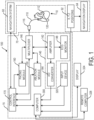
- data acquisition device 140 may be configured to provide as outputs therefrom saved or stored body surface electrogram signals, which can be, by way of example, saved or stored on a hard drive, in a memory, in the cloud, remotely, on a USB stick, or other suitable storage device, and where the saved or stored body surface electrogram signals are later or subsequently provided as inputs to computing device 300 for processing and analysis.
- multi-electrode catheter 110 is typically introduced percutaneously into the patient's heart 10.
- Catheter 110 is passed through a blood vessel (not shown), such as a femoral vein or the aorta, and thence into an endocardial site such as the atrium or ventricle of the heart 10.
- the electrogram signal data and/or controlled constant current signal data are processed by computer 300 to produce a display showing the locations(s) of the source(s) of cardiac rhythm disorders and/or irregularities in the patient's heart 10 in real-time or near-real-time, further details of which are provided below. That is, at and between the sampled locations of the patient's endocardium, computer 300 may be configured to compute and display in real-time or near-real-time an estimated, detected and/or determined location(s) of the site(s), source(s) or origin)s) of the cardiac rhythm disorder(s) and/or irregularity(s) within the patient's heart 10, and/or of the electrodes located at or near the distal end of catheter 110. This permits a medical practitioner to move interactively and quickly the electrodes of catheter 110 towards the location of the source of the cardiac rhythm disorder or irregularity.
- multiplexer 146 is separate from catheter 110 and data acquisition device 140, and in other embodiments multiplexer 146 is combined in catheter 110 or data acquisition device 140.
- system 100 includes ablation module 150, which may be configured to deliver RF ablation energy through catheter 110 and corresponding ablation electrodes disposed near distal end 112 thereof, and/or to deliver RF ablation energy through a different catheter (not shown in Fig. 1B).
- Suitable ablation systems and devices include, but are not limited to, cryogenic ablation devices and/or systems, radiofrequency ablation devices and/or systems, ultrasound ablation devices and/or systems, high-intensity focused ultrasound (HIFU) devices and/or systems, chemical ablation devices and/or systems, and laser ablation devices and/or systems.
- multi-electrode catheter 110 fitted with ablation electrodes, or a separate ablation catheter is energized by ablation module 150 under the control of computer 300, control interface 170, and/or another control device or module.
- ablation module 150 can initiate the delivery of a programmed series of electrical energy pulses to the endocardium via catheter 110 (or a separate ablation catheter, not shown in Fig. 1B).
- One embodiment of an ablation method and device is disclosed in U.S. Patent No. 5,383,917 to Desai et al..
- ablation module 150 is not controlled by computer 300, and is operated manually directly under operator control.
- pacing module 160 may also be operated manually directly under operator control.
- the connections of the various components of system 100 to catheter 110, to auxiliary catheters, or to surface electrodes may also be switched manually or using multiplexer 146 or another device or module.
- multi-electrode catheter 110 is energized by pacing module 160 operating under the control of computer 300 or another control device or module.
- pacing module 160 operating under the control of computer 300 or another control device or module.
- an operator may issue a command through input device 320 such that computer 300 controls pacing module 160 through control interface 170, and multiplexer 146 initiates the delivery of a programmed series of electrical simulating pulses to the endocardium via the catheter 110 or another auxiliary catheter (not shown in Fig. 1B).
- a pacing module is disclosed in M. E. Josephson et al., in "VENTRICULAR ENDOCARDIAL PACING II, The Role of Pace Mapping to Localize Origin of Ventricular Tachycardia," The American Journal of Cardiology, vol. 50, November 1982 .
- system 70 be controlled by computer 300 via control interface 170, or by other control means incorporated into or operably connected to imaging or navigation or positioning system 70.
- computer 300 or another computer triggers physical imaging or navigation system 60 to take "snap-shot" pictures of the heart 10 of a patient (body not shown).
- a picture image is detected by a detector 62 along each axis of imaging, and can include a silhouette of the heart as well as a display of the inserted catheter 110 and its electrodes A1-H8 (more about which is said below), which is displayed on imaging or navigation display 64.
- Digitized image or navigation data may be provided to computer 300 for processing and integration into computer graphics that are subsequently displayed on monitor or display 64 and/or 324.
- system 100 further comprises or operates in conjunction with catheter or electrode position transmitting and/or receiving coils or antennas located at or near the distal end of an EP mapping catheter 110, or that of an ablation or navigation catheter 110, which are configured to transmit electromagnetic signals for intra-body navigational and positional purposes.
- imaging or navigation system 60 is used to help identify and determine the precise two- or three-dimensional positions of the various electrodes included in catheter 110 within patient's heart 10, and is configured to provide electrode position data to computer 300. Electrodes, position markers, and/or radio-opaque markers can be located on various potions of catheter 110, mapping electrode assembly 120 and/or distal end 112, or can be configured to act as fiducial markers for imaging or navigation system 70. Alternatively, and as further described below, controlled constant current signals received by sensing or receiving electrodes included in mapping electrode assembly 120 or otherwise located on catheter 110 may be used to navigate or position catheter 110, or to provide images of the locations of such electrodes or portions of catheter 110.
- Medical navigation systems suitable for use in the various embodiments described and disclosed herein include, but are not limited to, image-based navigation systems, model-based navigation systems, optical navigation systems, electromagnetic navigation systems (e . g ., BIOSENSE ® WEBSTER ® CARTO ® system), impedance-based navigation systems (e . g ., the St. Jude ® ENSITE TM VELOCITY TM cardiac mapping system), systems that combine attributes from different types of imaging and navigation systems and devices to provide navigation within the human body (e . g ., the MEDTRONIC ® STEALTHSTATION ® system), and various embodiments of the controlled constant current navigation, positioning and/or imaging system described in detail below.
- image-based navigation systems e . g ., BIOSENSE ® WEBSTER ® CARTO ® system
- impedance-based navigation systems e . g ., the St. Jude ® ENSITE TM VELOCITY TM cardiac mapping system
- portions of the described devices and methods may be configured as processes, methods, data processing systems, and/or computer methods. Accordingly, these portions of the devices and methods described herein may take the form of a hardware embodiment, a software embodiment, or an embodiment combining software and hardware, such as shown and described with respect to computer system 300 illustrated in Fig. 2 . Furthermore, portions of the devices and methods described herein may be a process or method stored in a computer-usable storage medium having computer readable program code on the medium. Any suitable computer-readable medium may be utilized including, but not limited to, static and dynamic storage devices, hard disks, optical storage devices, and magnetic storage devices.
- These computer-executable instructions may also be stored in a computer-readable memory that can direct computer 300 or other programmable data processing apparatus to function in a particular manner, such that the instructions stored in the computer-readable memory result in an article of manufacture including instructions which implement the function specified in an individual block, plurality of blocks, or block diagram.
- the computer program instructions may also be loaded onto computer 300 or other programmable data processing apparatus to cause a series of operational steps to be performed on the computer or other programmable apparatus to produce a computer implemented process such that the instructions which execute on computer 300 or other programmable apparatus provide steps for implementing the functions specified in an individual block, plurality of blocks, or block diagram.
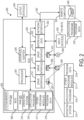
- FIG. 2 illustrates only one example of a computer system 300 (which, by way of example, can include multiple computers or computer workstations) that can be employed to execute one or more embodiments of the devices and methods described and disclosed herein, such as devices and methods configured to acquire and process sensor or electrode data, to process image data, to process received controlled constant current constant electrical signals, and/or transform sensor or electrode data and image data associated with the analysis of cardiac electrical activity and the carrying out of the combined electrophysiological mapping and analysis of the patient's heart 10 and ablation therapy delivered thereto.
- a computer system 300 which, by way of example, can include multiple computers or computer workstations
- devices and methods configured to acquire and process sensor or electrode data, to process image data, to process received controlled constant current constant electrical signals, and/or transform sensor or electrode data and image data associated with the analysis of cardiac electrical activity and the carrying out of the combined electrophysiological mapping and analysis of the patient's heart 10 and ablation therapy delivered thereto.
- Computer system 300 can be implemented on one or more general purpose computer systems or networked computer systems, embedded computer systems, routers, switches, server devices, client devices, various intermediate devices/nodes or standalone computer systems. Additionally, computer system 300 or portions thereof may be implemented on various mobile devices such as, for example, a personal digital assistant (PDA), a laptop computer and the like, provided the mobile device includes sufficient processing capabilities to perform the required functionality.
- PDA personal digital assistant
- computer system 300 includes processing unit 301 (which may comprise a CPU, controller, microcontroller, processor, microprocessor or any other suitable processing device), system memory 302, and system bus 303 that operably connects various system components, including the system memory, to processing unit 301. Multiple processors and other multiprocessor architectures also can be used to form processing unit 301.
- System bus 303 can comprise any of several types of suitable bus architectures, including a memory bus or memory controller, a peripheral bus, or a local bus.
- System memory 302 can include read only memory (ROM) 304 and random-access memory (RAM) 305.
- BIOS basic input/output system
- BIOS basic input/output system
- BIOS basic input/output system
- computer-readable media refers to a hard disk, a removable magnetic disk and a CD
- other types of media that are readable by a computer such as magnetic cassettes, flash memory cards, digital video disks and the like, in a variety of forms, may also be used in the operating environment; further, any such media may contain computer-executable instructions for implementing one or more parts of the devices and methods described and disclosed herein.
- a number of program modules may be stored in drives and RAM 303, including operating system 315, one or more application programs 316, other program modules 313, and program data 318.
- the application programs and program data can include functions and methods programmed to acquire, process and display electrical data from one or more sensors, such as shown and described herein.
- the application programs and program data can include functions and methods programmed and configured to process data acquired from a patient for assessing heart function and/or for determining parameters for delivering a therapy and/or assessing heart function, such as shown and described herein.
- a health care provider or other user may enter commands and information into computer system 300 through one or more input devices 320, such as a pointing device (e.g., a mouse, a touch screen, etc.), a keyboard, a microphone, a joystick, a game pad, a scanner, and the like.
- input devices 320 such as a pointing device (e.g., a mouse, a touch screen, etc.), a keyboard, a microphone, a joystick, a game pad, a scanner, and the like.
- the user can employ input device 320 to edit or modify the data being input into a data processing method (e.g., only data corresponding to certain time intervals).
- These and other input devices 320 may be connected to processing unit 301 through a corresponding input device interface or port 322 that is operably coupled to the system bus, but may be connected by other interfaces or ports, such as a parallel port, a serial port, or a universal serial bus (USB).
- One or more output devices 324
- Computer system 300 may operate in a networked environment employing logical connections to one or more remote computers, such as remote computer 328.
- Remote computer 328 may be a workstation, a computer system, a router, or a network node, and may include connections to many or all the elements described relative to computer system 300.
- the logical connections, schematically indicated at 330, can include a local area network (LAN) and/or a wide area network (WAN).
- LAN local area network
- WAN wide area network
- computer system 300 When used in a LAN networking environment, computer system 300 can be connected to a local network through a network interface or adapter 332. When used in a WAN networking environment, computer system 300 may include a modem, or may be connected to a communications server on the LAN. The modem, which may be internal or external, can be connected to system bus 303 via an appropriate port interface. In a networked environment, application programs 316 or program data 318 depicted relative to computer system 300, or portions thereof, may be stored in a remote memory storage device 340.
- a controlled constant current navigation or positioning, and optionally imaging, system 60 which in the illustrated embodiment comprises principal components: (a) received constant current signal conditioning and conversion module 60A; (b) computer 60B/300; (c) navigation, position and/or image display module 60C; (d) constant current signal receiving catheter 60D; (e) body surface electrode system 60E, and (f) controlled constant current system 60F.
- a) received constant current signal conditioning and conversion module 60A a computer 60B/300
- c navigation, position and/or image display module 60C
- constant current signal receiving catheter 60D e
- body surface electrode system 60E body surface electrode system 60E
- controlled constant current system 60F body surface electrode system
- a patient 5 wearing a body surface electrode vest 420 comprising a plurality of body surface electrodes 430, which are operably connected to module 60F through electrical connection 410.
- a high frequency RF generator 149 generates signals that are provided to high-fidelity controlled constant current source 151, which is configured to emit selectable current signals having a degree of accuracy and repeatability.
- the controlled constant current signals output from constant current source 151 are next provided to multiplexer 153, and thence to medical device/catheter connection 410 and body surface electrodes 430.
- Body surface electrodes 430 and module 60F of system 100 are configured to deliver individual, high-fidelity, controlled, constant current, electrical signals to the volume of interest located beneath electrodes 430.
- each electrode 430 transmits into the volume or region of interest a controlled constant current signal which is different in phase, amplitude and/or frequency from the controlled constant current signals transmitted by other electrodes 430.
- electrodes 430 may be configured to emit controlled constant current electrical signals that have the same or similar phases, amplitudes and/or frequencies, but which owing to their different locations on the surface of the patient's body, and the different portions of body 5 such signals traverse on their way to sensing or receiving electrodes located within the volume, can result in such signals having different distinguishable characteristics when they arrive at the various sensing or reception electrodes located within the volume and patient's body 5.
- each body surface electrode 430 transmits a controlled constant current signal having its own unique AC frequency.
- Such unique AC frequency signals can then be detected by electrodes located on medical device or catheter 110, and using appropriate analog signal bandpass or other digital filtering techniques be differentiated from one another to yield 3D electrode positions.
- each body surface electrode 430 transmits a controlled constant current signal that is received by each sensing electrode within the volume as a unique controlled constant current signal owing to, for example, phase, frequency and/or amplitude differences.
- Module 60A of system 100 is configured to receive and process the controlled constant current electrical signals transmitted by electrodes 430 and sensed or received by electrodes located on medical device or catheter 110. Such received or sensed controlled constant current electrical signals are routed from medical device or catheter 110 through electrical connection 123 to module 60A. (Wireless connections may also be employed to replace electrical connection 123.) Preamplifier 143 is amplify configured to receive the controlled constant current signals sensed or received thereby, and to condition and convert such signals for further processing by bandpass filter 145. In some embodiments, electrical connection or cable 123 or 410 can be replaced by a wireless connections, such as BLUETOOTH ® connection. In one embodiment, and as shown in Fig.
- sensing or receiving electrodes located on medical device 110 may also be configured to perform other functions, such as to act as fiducial markers, ablation electrodes, pacing electrodes, defibrillation electrodes, and so on.
- 16 body surface electrodes 430 are mounted on, attached to, or operably coupled to patient 5's thorax or body above the volume (or region of interest).
- a corresponding ground electrode pad or one or more ground electrodes are optimally placed diametrically opposite transmitting electrodes 430 on the patient back.
- Other numbers and configurations of body surface and ground electrodes are also contemplated.
- ground electrodes many options exist, including no explicitly provided ground electrode (a ground will nearly always be found for a transmitted electrical signal), substitutes for specific or discrete ground electrodes such as a metal or electrically conductive bed or surgery platforms, pans, leashes, collars, and so on.
- the numbers of electrodes employed may range, by way of non-limiting example, between 1 electrode and 3 electrodes, 4 electrodes, 8 electrodes, 12 electrodes, 16 electrodes, 24 electrodes , 36 electrodes, 48 electrodes, 64 electrodes, 72 electrodes, 96 electrodes, 128 electrodes, 256 electrodes, 512 electrodes, and 1,024 electrodes.
- Some examples of current manufacturers of cardiac monitoring patches which in at least some cases may be adapted or configured for use as electrode patches configured to transmit or deliver controlled constant current signals, include: (a) iRhythm ® and their Zio XT ® and Zio T ® Patch product offerings; or (b) the Bardy Dx ® Carnation Ambulatory Monitor (CAM TM ). Electrodes configured to operate wirelessly, such as those found in the NUVANT ® Mobile Cardiac Telemetry (MCT) Monitor, which communicates wirelessly with a cellular device, are also contemplated.
- MCT Mobile Cardiac Telemetry
- Apple iWatch ® , FitBit ® , Galaxy Watch3 ® , and Galaxy Watch Active2 ® are examples of watch or watch-like devices configured to acquire cardiac data from the wearer, such as ECGs, blood pressure, heart rate, etc..
- Such wearable devices likewise contain certain aspects and features that can be employed in, or adapted and modified for use in, the systems, devices, components, and methods described and disclosed herein.
- FIG. 3 there are shown 16 body surface electrodes 430 mounted on the anterior portion of vest 420, which in turn is worn on or attached to the thorax of patient 5.
- another 16 body surface electrodes 430 may be mounted on a posterior surface of vest 420 (not shown in Fig. 3 ).
- body surface electrodes 430 may be mounted, attached or coupled to the patient's thorax by means other than a vest, such as by patches, electrode strips, individually, or by other means known in the art.
- electrode strips manufactured by Goltec GmbH of Cremlingen, Germany can be used.
- Carbon and metal body surface electrode strips are available from Goltec GmbH. Carbon electrode strips have the advantage of being radio-translucent, i . e ., being transparent or substantially transparent during X-ray imaging.
- Electrodes may be provided only on the anterior portion of the patient's thorax, only on the posterior portion of the patient's thorax, on side or lateral portions of the patient's thorax, or on any suitable combination of anterior, posterior and/or lateral portions of the patient's thorax.
- transmitting electrodes 430 can be positioned above or below the volume, where the region of interest includes, by way of non-limiting example, patient 5's brain, stomach, kidneys, bladder, colon, large intestine, small intestine, and/or any other internal organ, passageway, or the like which is to be investigated and analyzed using, for example, a catheter or other device configured to be placed inside the human body.
- electrodes 430 are configured to transmit controlled constant current electrical signals in the direction of or into a volume containing or encompassing patient's heart 10.
- other types of devices and/or transducers such as ground electrodes, navigation patches, position markers, or other devices may be configured to operate in conjunction with, be incorporated into, or form a portion of vest 420, electrodes 430, and/or system 100.
- Electrodes 430 may be reusable or disposable, unipolar or bipolar, and may be configured for use with MRT/MRI, X-Ray, and/or CAT scanning imaging systems or other types of imaging systems 60.
- Imaging and/or navigation system 60 may also be employed used to help identify and determine the precise positions of the various electrodes 430 or position markers included in vest 430.
- Gels, adhesives, and liquids may be employed to improve electrical coupling of electrodes 430 with the patient's body, as is well known in the art.
- Electrodes 430 may be reusable or disposable, unipolar or bipolar, and may be configured for use with MRT/MRI, X-Ray, and/or CAT scanning imaging systems or other types of imaging systems 60.
- system 100 of Figs.1 and 3 may not include multiplexer 146, ablation module 150, pacing module 160, imaging and/or navigation system 60, or other modules or components shown in Figs. 1 and 3 .
- the embodiments of system 100 shown in Figs. 1 and 3 may be configured to detect and reconstruct cardiac activation information acquired from a patient's heart relating to cardiac rhythm disorders and/or irregularities, and may further be configured to detect and discover the locations of the source of such cardiac rhythm disorders and/or irregularities with enhanced precision relative to prior art techniques using body surface electrodes 430.
- system 100 is further configured to treat the location of the source of the cardiac rhythm disorder or irregularity, for example by ablating the patient's heart at the detected source location.
- the embodiment of system 100 shown in Figs. 1 and 3 may include at least one computer or computing device or system 300 employed to control the operation of one or more of systems, modules and/or devices included in 60, 70, 100, 140, 150, 160, and 170.
- the respective operations of systems, modules or devices 60, 70, 100, 140, 150, 160, and 170 may be controlled separately by each of such systems, modules and devices, or by some combination of such systems, modules and devices.
- body surface electrodes 430 are positioned on the thorax of patient 5, and by way of example may be mounted on a vest 420 that is configured to place individual electrodes 430 in predetermined positions on the patient's body. These predetermined electrode positions can also be provided to imaging and/or positioning or navigation system 60 and/or to computer 300 as a data file so that the spatial positions of body surface electrodes 430 are known (at least approximately), and so that EGF and/or navigation/positioning/imaging analysis can be carried out as described and disclosed herein.
- body surface electrodes 430 may also function as detectors of electrocardiographic signals.
- the analog signals obtained from body surface electrodes 430 can be routed by multiplexer 146 to data acquisition device 140, which comprises an amplifier 142 and an A/D converter (ADC) 144.
- ADC A/D converter
- the amplified or conditioned electrogram signals may be displayed by electrocardiogram (ECG) monitor 148.
- ECG electrocardiogram
- the analog signals may also be digitized via ADC 144 and input into computer 300 for data processing, EGF analysis and graphical display.
- controlled constant current medical device navigation, positioning and imaging technology employs an approximately two-dimensional scanning method, where a controlled constant current source is located over the chest of patient 5 where heart 10 is located.
- scanning is performed using a matrix or array of skin or body surface electrodes 430 driven by a multiplexer 153, and applying a spherically divergent field of electrical current in the long wave RF range of frequency.
- the voltage profile created by the current within the heart chambers and the volume is independent from the access resistances of individual electrodes 430.
- the matrix of electrodes 430 of known spacing D1 and D2 allows the controlled constant current scan to directly provide absolute rectangular coordinates.
- a coronary sinus (CS) or other catheter can be used as a reference.
- the local shape of a QRS complex in an electrogram which differs depending on a catheter electrode's location, can be mapped to 3D space using, for example, a neural network where the QRS shapes detected at each CS electrode on a CS catheter are monitored in real time or near-real-time, and shifts in position of the catheter are detected by determining whether the shapes of the QRS complexes exceed a predetermined threshold or other pertinent parameter. See: (a) U.S. Patent Application Serial No. 17/831,249 to Tenbrink et al.
- Figs. 4-23 overall controlled constant current technology will be seen to offer a unique approach to navigation, positioning and imaging that provides accurate, high-resolution imaging of the heart or a medical device without being affected by electrode access or input resistances or impedances, or patient movements.
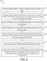
- Fig. 4 illustrates one method of employing some of the embodiments of the controlled constant current navigation, positioning and/or imaging systems described and disclosed herein.
- a model of a volume, or region or volume of interest, comprising voxels is generated for the patient's body.
- the model or volume is specifically generated to include and focus upon patient's heart 10, and may incorporate details regarding a specific patient's age, size, sex, body mass index (BMI), fatness, leanness, or thickness of tissue, musculature, bone characteristics, and/or cardiac characteristics (e.g., cardiomyopathy, etc.).
- BMI body mass index
- step 402 electrical signal values corresponding to controlled constant current signals transmitted from body surface electrodes 430 located on the patient's body 5 to the voxels in the volume are generated.
- body surface electrodes 430 are positioned and operably coupled on or to patient's 5's body surface.
- a medical device or portion thereof (such as a catheter) is positioned inside the patient's body and within the volume, where the medical device comprises receiving or sensing electrodes configured to receive controlled constant current signals transmitted by body surface electrodes 430.
- controlled constant current electrical signals are delivered to body surface electrodes 430 and transmitted into the volume or region of interest through electrodes 430.
- step 411 electrical signals corresponding to constant current electrical signals transmitted to and received by sensing electrodes mounted on near the medical device are acquired by the sensing ort receiving electrodes located on the medical device.
- step 413 the sensed constant current electrical signals values and the expected electrical signal values corresponding thereto are employed to determine the three-dimensional locations of the medical device sensing or receiving electrodes located inside the patient 5's body and within the volume or region of interest.
- the expected electrical signal values are generated using the known predetermined amplitudes, phases, and/or frequencies of the unique transmitted controlled constant current signals generated, or that are to be generated, by constant current source 151 and transmitted into the volume or region of interest by electrodes 430 for reception or sensing by electrodes located on medical device or catheter 110.
- steps 410 through 413 further aspects of such steps may include one or more of the following: (a) body surface electrodes 430 being configured for placement on or over a first portion of the patient 5's body surface; (b) a plurality of receiving or sensing electrodes mounted on or attached to the catheter or medical device 110, each such electrode having a predetermined location or position on or in the catheter or medical device; (c) at least one controlled constant current source 151 configured to be operably connected to the plurality or selected ones of the body surface electrodes 430 and to transmit controlled constant current signals therethrough; (d) a data acquisition or recording device 60A operably connected to at least one computing device 60B/300, the data acquisition or recording device 60A being operably connected to the catheter or medical device electrodes and configured to acquire, or store or record, electrical signals corresponding to transmitted controlled constant current signals sensed by at least some of the plurality of catheter electrodes as sensed electrical signals; (e) the data acquisition or recording device 60A further being configured to relay sensed electrical signals to computing device 60
- Still further aspects of employing some of the embodiments of the controlled constant current navigation, positioning and/or imaging systems described and disclosed herein include, but are not limited to, the following: (a) following the given period of time, and during subsequent given periods of time, continuing to: (i) transmit controlled constant current signals through the body surface electrodes 430 into patient's body 5 and the at least portion of the volume; (b) acquire sensed electrical signals; (c) store or record sensed electrical signal values, and (d) determine, on the basis of the sensed electrical signal values and expected electrical signal values corresponding thereto, subsequent three-dimensional locations of the catheter or medical device electrodes located within patient's body 5 and the at least portion of the volume during each or selected ones of the subsequent given periods of time, thereby to permit navigation, positioning and/or imaging of the catheter or medical device 100, or portion thereof, inside patient's body 5.
- the at least one three-dimensional location of at least one of the catheter or medical device electrodes is located within patient's heart 10, and further wherein the at least portion of the volume is located within the patient's heart; (b) using controlled constant current signals sensed by or transmitted from a coronary sinus catheter to compensate for at least one of movements of the patient's atria with heartbeat, movements resulting from the patient breathing, and other patient movements; (c) sensing cardiac electrical signals from the patient's heart, determining at least one shape of the patient's QRS complex from the cardiac electrical signals, and verifying or improving the accuracy of the determination of the at least one three-dimensional location provided by the controlled constant current navigation, positioning or imaging system 100; (d) using the sensed electrical signals, reconstructing and displaying a geometry or visual model of the catheter or medical device 110; (e) using the sensed electrical signals, generating an
- voxels are individual volume elements, and each voxel represents a value in a three-dimensional space, which in turn can correspond to a pixel for a given slice thickness. Voxels are frequently used in the visualization and analysis of medical data, such as MRIs.
- the volume or region of interest has dimensions of 15 cm ⁇ 15 cm ⁇ 15 cm, and individual voxels having dimensions of 1 mm ⁇ 1 mm ⁇ 1 mm, for a total of 3,375,000 voxels.
- receiving or sensing electrode 3D positions within the volume are associated with specific voxels within the volume, more about which is said below.
- the controlled constant current scanning method can be done quickly, and by way of non-limiting example is capable of providing the positions of 12, 24, 36, 48, 64, 128 or other numbers of independent catheter or medical device electrodes about every 200 msec. by, for example and in one embodiment, exploiting state of the art machine learning techniques to define a 3D space or volume after extracting a compensatory transformation matrix to eliminate distortions.
- Other time sampling or presentation intervals are also contemplated, such as about every 25 msec., about every 50 msec., about every 100 msec., about every 300 msec., about every 400 msec., about every 1 second, or any other suitable or useful time interval.
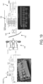
- Controlled constant current technology can interface with the Ablamap amplifier (see, e . g ., Figs. 18 and 19 ), and display results as 3D reconstructions of any catheter or medical device geometry (e . g ., a basket catheter, a pFix catheter, a loop ablation catheter, a pulse filed ablation catheter, a coronary or CS catheter, an ablation catheter, and other medical devices and device geometries) in real time or near-real-time together with the results of Ablacon's Ablamap EGF mapping system.
- catheter or medical device geometry e . g ., a basket catheter, a pFix catheter, a loop ablation catheter, a pulse filed ablation catheter, a coronary or CS catheter, an ablation catheter, and other medical devices and device geometries
- Controlled constant current technology can also be used to generate an anatomical shell (for example by using basket catheter, pFix catheter or ablation catheter outlines in the heart 10), and onto which mapping results created with the Ablamap system may then be projected.
- controlled constant current navigation, positioning and/or imaging systems include, but are not limited to, the following: (a) employ a matrix or array of controlled constant current sources in the RF frequency range, optionally combined with bioelectric signals ( e .
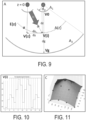
- Fig. 8 As regards basic concepts of controlled constant current navigation, positioning and/or imaging according to some embodiments, and with reference to Fig. 8 , we can start by considering 16 ⁇ 1 cm electrode patches on the chest of size A 1 (100 mm 2 and size s 1 10 mm), a body conductivity ⁇ (e.g., 7 e -4 S/mm), and a constant current I C of 10 mA multiplexed through any surface patches of size A 1 .
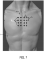
- chest electrodes 430 are assumed to be equally spaced (4 ⁇ 4 electrodes in 50 mm distance) in the x (from left to right) and y (from bottom to top) directions. See Figs. 6 and 7 .
- A is assumed to increase linearly from A 1 to A 2 and can be projected in the ventral direction to an infinitely small A 0 , where the field would theoretically be infinitely strong.
- V z I c A 1 ⁇ ⁇ ⁇ ⁇ 1 z d 0 + 1 2 dz
- V z I c ⁇ d 0 A 1 ⁇ ⁇ ⁇ ⁇ 1 z d 0 + 1 + C
- V z I c ⁇ d 0 A 1 ⁇ ⁇ ⁇ 1 z d 0 + 1 ⁇ 1 d g d 0 + 1
- V i I c ⁇ d 0 A 1 ⁇ ⁇ ⁇ 1 dx 2 + dy 2 + dz 2 d 0 + 1 ⁇ 1 d g d 0 + 1
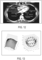
- Equation (1) can be solved to yield x c , y c and z c , the coordinates of our catheter electrode by fitting the maximum of V ( c ) of the surface of V ( i ) in dependence of the 4 ⁇ 4 matrix of the surface electrodes (see Fig. 11 ).
- V ( i ) Since the voltage V ( i ) is measured between A ( z ) and A 2 it depends on current density and conductance between the A ( z ) and A 2 . Because of the constant current source V 0 but not the current density at A ( z ) depends on the conductance between A 1 and A(z). Hence V ( i ) is independent on conductivity differences below the body surface electrodes and depends only on geometry.
- the x-y location can be fitted into this matrix along with the virtually maximal voltage, yielding the z -value according to the derived equation for V ( i ) .
- the x, y , and z values are all determined by the same fit.
- This method has a critical advantage: any distortion due to variable conductance values in the tissue between the electrodes is simply and simultaneously reflected in all values. By using the known dimensions of catheters with multiple electrodes, these distortions can be eliminated through simple linear transformations in the obtained 3D space.
- this signal is also suited to monitor and compensate for time-dependent shifts in the conductivities due to patient movements or changes in body hydration.
- the scanning process is crucial for determining the precise location of the catheter or medical device electrode within the body.
- V noise is the noise in volts
- k is the Boltzmann constant (1.38064852 ⁇ 10 -23 J/K)
- T is the temperature in Kelvin (body temperature: approximately 37°C or 310.15 K)
- R is the resistance in Ohms
- B is the bandwidth in Hertz.
- V noise is about 0.26 ⁇ V at a body temperature of 37°C and a bandwidth of 20 kHz.
- a sensitivity analysis of controlled constant current navigation, positioning and imaging technology may be carried out as follows.
- the sensitivity of the controlled constant current scanning process is calculated as change in voltage due to a 1 mm movement in the x, y, and z -directions in relation to the theoretical noise value.
- Fig. 16 illustrates the change in signals from all 16 electrodes.
- Some of the surface electrode signals show a much larger change in amplitude upon the 10 mm shift (as much as 5 mV).
- the fitted distance between the electrodes E4 and E5 yields the expected 10 mm distance very accurately and the two fits differ by several mV, which is more than 10-fold above the noise level.
- Fig. 17 illustrates the difference between a forward model electrical field computation and that which may occur in actual practice.
- Figs. 18 and 19 show one embodiment of an AblaNav controlled constant current navigation, positioning and imaging module or box, which generates high-precision, high-fidelity, controlled constant current signals and multiplexes them for transmission through body surface electrodes 430 into the volume or region of interest.
- the AblaNav module or box also receives, amplifies, filters and digitizes the corresponding sensed signals received from electrodes positioned on catheter or medical device 110. Referring to Fig.
- controlled constant current source 151 is configured and/or calibrated to provide as outputs therefrom constant current signals that have an amplitude variation from a specified output value of no more than about 1 % upon doubling of the electrode resistance or impedance per channel; as described above, the accuracy, controllability and fidelity of constant current outputs from current source 151 are important.
- a sufficiently accurate controlled constant current source 151 capable of transmitting low-variation output signals into a patient's body 5 is required to yield a suitable navigation signal within the volume or region of interest: Navigating with a properly configured controlled constant current source can significantly improve the precision of internal body distance measurements and navigation.
- a controlled constant current source 151 that is configured to automatically adjust the overall voltages at each body surface electrode 430 so as to compensate for any potential variability in resistance or impedance at the skin-electrode interface or for differences in tissue types.
- the system's ability to self-adjust for resistance and impedance variations enables the navigation system 60 to provide precise measurements of distances within the body 5, making it an optimal choice for such applications.
- This technique is particularly effective if using highfrequency alternating current (e.g., about 1 kHz to about 1 MHz), which is well-conducted by body tissues, particularly those with cell membranes, and by measuring sensed or received voltages against a reference electrode located on the patient's back.
- modules 60F and 60A may be employed in modules 60F and 60A as follows:
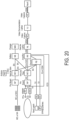
- Fig. 20 shows one embodiment of an electrical circuit block diagram for a system 100 comprising various components from Figs. 1 , 3 , 18 and 19 , including body surface electrodes 430 (NavX patch), the AblaNav Box, and body surface electrodes for electrophysiological (EPMap patches), along with other modules and components that may be employed in a controlled constant current navigation, positioning and imaging system.
- body surface electrodes 430 NavX patch
- AblaNav Box AblaNav Box
- EPMap patches electrophysiological
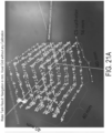
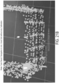
- Figs. 21A and 21B show water tank results achieved using the AblaNav module, without calibration.
- Fig. 21 A shows the results of precision and drift tests to determine the localization accuracy of system 60/100 in a 28 cm water tank with 16 electrodes arranged in a 4 ⁇ 4 array with 5 cm spacing on one side, and a 20 ⁇ 20 cm large electrode on the other side.
- the elongated structure at the bottom of Fig. 21A represents a static decapolar catheter located at a distance of approximately 50 mm from the electrode matrix.
- the elongated vertical small structure in the upper left-hand corner of Fig. 21A represents a quadripolar catheter, which was oriented perpendicular to the matrix. Only two electrodes on the tip of the quadripolar were captured.
- Fig. 21A represents one of the electrode positions captured every 10 seconds over the course of one hour.
- a robotic arm having the quadripolar catheter mounted thereon was instructed to move in sequential 40 ⁇ 40 mm square outlines at different heights to achieve the resulting cubical shape shown in Fig. 21A .
- Fig. 21B shows a 1 mm voxel grid scale (small squares) compared with recorded data.
- Fig. 21B illustrates that a high degree pf accuracy in 8 mm robot movement steps in the 3D representation is provided by the navigation system 60/100.
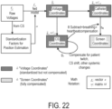
- Fig. 22 shows a block diagram for performing controlled constant current or current scanning navigation, positioning and/or imaging.
- the following accompanying pseudo-code and details provide further details regarding the block diagram of Fig. 22 and its operation.
- electrical signal values expected to be received by sensing or receiving electrodes located on medical device or catheter 110 within the volume or region of interest are generated for comparison to the controlled constant current signals that are actually received by sensing or receiving electrodes located on medical device or catheter 110 within the volume or region of interest.
- a model of the volume or region of interest comprising voxels (e.g., a volume or region of interest having dimensions of 15 cm ⁇ 15 cm ⁇ 15 cm, and individual voxels having dimensions of 1 mm ⁇ 1 mm ⁇ 1 mm, for a total of 3,375.000 voxels) is generated.
- the model of the volume or region of interest may be configured to take into account numerous factors associated with the particular patient at hand, such as the patient's age, size, sex, body mass index (BMI), fatness, leanness, or thickness of tissue, musculature, bone characteristics, and/or cardiac characteristics (e.g., cardiomyopathy, etc.).
- BMI body mass index
- a finite element simulation and analysis is carried out as a pre-calculation step.
- the volume or region of interest is divided into finite elements comprising 1 mm cubes, and for each cube a calculation of its expected voltage value is performed. These voltage values and their corresponding locations can then be stored in an efficient lookup table.
- voltage "fingerprints" sensed by electrodes on catheter or medical device 100 are compared to expected voltage values in the lookup table to find corresponding finite element values, which by construction all have 3D spatial coordinates corresponding thereto.
- h i x v 0 i x ⁇ r i d 0 + 1 ⁇ v 0 i x ⁇ r i + 0 0 ⁇ 2 d g d 0 + 1 ⁇ v 1 x z + d g d 1 + 1 + v 1
- a feedforward network maps an input x to a category y .
- the parameters ⁇ are adjusted, so that the output of the network of the given example x is close to the expected label y . This difference between the output and the expected label y is called loss.
- the adjustment of ⁇ is done usin a gradient-learning approach.
- a feedforward neural network consists of multiple layers, with a layer being defined as multiple neurons. All neurons of one layer are connected with all neurons of the next layer. Those neuron-to-neuron connections are weighted. Each neuron also has a bias, which is just a scalar value.
- the output of a neuron is the sum of the weighted inputs ⁇ i n w i x i plus the bias b . This output is then fed into a non-linear activation function a , so that the network can also learn non-linear functions.
- the overall function of a single neuron is defined as: a ⁇ i n w i x i + b , with n being the number of neurons in the previous layer.
- Feed forward networks have the major drawback that each neuron has its own connection, i.e., weight to each neuron in the next layer. Using multiple layers with multiple neurons lets the number of weights explode very quickly.
- Convolutional neural networks make use of weight sharing.
- Convolutional layers consist of a set of kernels (also called filters) that are convolved with the input.
- a convolution can be seen as a dot product between the kernel and the input. All values of the input are multiplied by their corresponding value (also called weighting) in the kernel. Then all values are summed up resulting in a scalar output.
- Fig. 5 One example of a convolution operation is visualized in Fig. 5 .
- Stacking multiple convolutional layers allows a network to learn more and higher-level features. For example, in image processing the first convolution layers learn edges and corners, and then later layers learn full objects.
- a 3 ⁇ 3 kernel is convolved over a 5 ⁇ 5 input zero padding and unit strides, resulting in the output (green).
- An autoencoder is a neural network that is trained to output a given input. Internally, it has a hidden layer h that describes a code used to represent the input.
- Undercomplete autoencoders constrain h to have a smaller dimension than x. Learning an undercomplete representation forces the autoencoder to capture the most salient features of the training data.
- the learning process may be described simply as minimizing a loss function L ( x , g ( f ( x ))), where L is a loss function penalizing g ( f ( x )) for being dissimilar from x.
- Regularized autoencoders provide the ability to train an autoencoder which fulfills other properties besides reconstructing the input.
- Autoencoders exploit the idea that data concentrates around a low-dimensional manifold or a small set of such manifolds. Autoencoders are configured to learn the structure of a manifold. An important characterization of a manifold is the set of its tangent planes. At a point x on a d -dimensional manifold, the tangent plane is given by d basis vectors that span the local directions of variation allowed on the manifold. These local directions specify how one can change x infinitesimally while staying on the manifold.
- the underlying idea is that the two terms together force the hidden representation to capture information about the structure of the input data.
- a discriminative training (DT) machine learning model works in combination with a loss or cost function module (or LM).
- the DT MLM is configured to provide its results or predictions to the LM, and in turn the LM is configured to provide outputs based on the DT MLM's results or predictions back to the DT MLM (more about which is said below).
- the DT MLM can be any suitable type of machine learning module or network, such as one or more of the following types of networks or modules: convolutional neural network (CNN), decision tree, support vector machine, logistic regression, mixture of Gaussian, a feedforward neural network or artificial neuron network, a radial basis function neural network, a Kohonen self-organizing neural network, a recurrent neural network(RNN) or long short term memory network, and/or a modular neural network.
- CNN convolutional neural network
- decision tree support vector machine
- logistic regression mixture of Gaussian
- a feedforward neural network or artificial neuron network a radial basis function neural network
- a Kohonen self-organizing neural network a recurrent neural network(RNN) or long short term memory network
- RNN recurrent neural network
- An input signal x to a machine learning model DT may comprises data recorded from catheter or medical device 110 electrodes BS (x).
- signal x potentially undergoes preprocessing steps, such as a high/low/band-pass filtering.
- the desired output(s) y of the machine learning model provides an estimate(s) for one or more properties of the constant current signals detected in the patient's heart 10.
- Training data (x, y) can be obtained from simultaneous recordings from body surface electrodes (x) and intracardiac electrodes (y).
- the machine learning model is parametrized with parameters W. These can be weights of neural network connections, etc.
- parameters W are optimized so as to minimize the error in estimating y.
- a DT MLM can be trained to directly predict electrode positions using sensed electrical signal values and expected electrical signal values corresponding thereto, thereby to provide subsequent three-dimensional locations of the catheter or medical device electrodes located within patient's body 5 and the at least portion of the volume during each or selected ones of the subsequent given periods of time, thereby to permit navigation, positioning and/or imaging of the catheter or medical device 100, or portion thereof, inside patient's body 5.
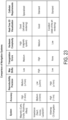
- Fig. 23 shows a table comparing various different types of well-known medical navigation systems, in addition to the controlled constant current navigation system (Ablamap CS-Navigation system) described and disclosed herein.
- Such systems in addition to the controlled constant current navigation system described and disclosed herein include the Carto system, the Ensite system, the Rhythmia system, the Affera system, the NavX system the Acutus system, and the CardioNXT system.
- the Ablamap CS-Navigation system delivers very high positional accuracy (within 1 mm in some embodiments), high reproducibility precision (+ or - 1 mm in some embodiments, low levels of map shift, no triangulation errors, low hardware complexity, excellent state-of-the-art real-time 3D visualization, and the ability to use standard catheters already in widespread use.
- the Ablamap CS-Navigation system (or controlled constant current navigation, positioning and imaging system) described and disclosed herein has many advantages and overcomes many hurdles and difficulties presented by prior art navigation system, including, but not limited to, significantly lower system cost, increased ease of use, improved accuracy, and faster real-time results.
- portions of the described devices and methods may be configured as methods, data processing systems, or computer methods. Accordingly, these portions of the devices and methods described herein may take the form of a hardware embodiment, a software embodiment, or an embodiment combining software and hardware, such as shown and described with respect to computer system 300 illustrated in Fig. 2 . Furthermore, portions of the devices and methods described herein may be a computer method stored in a computer-usable storage medium having computer readable program code on the medium. Any suitable computer-readable medium may be utilized including, but not limited to, static and dynamic storage devices, hard disks, optical storage devices, and magnetic storage devices.
- These computer-executable instructions may also be stored in a computer-readable memory that can direct computer 300 or other programmable data processing apparatus to function in a particular manner, such that the instructions stored in the computer-readable memory result in an article of manufacture including instructions which implement the function specified in an individual block, plurality of blocks, or block diagram.
- the computer program instructions may also be loaded onto computer 300 or other programmable data processing apparatus to cause a series of operational steps to be performed on the computer or other programmable apparatus to produce a computer implemented process such that the instructions which execute on computer 300 or other programmable apparatus provide steps for implementing the functions specified in an individual block, plurality of blocks, or block diagram.
- FIG. 2 illustrates only one example of a computer system 300 (which, by way of example, can include multiple computers or computer workstations) that can be employed to execute one or more embodiments of the devices and methods described and disclosed herein, such as devices and methods configured to acquire and process sensor or electrode data, to process image data, and/or transform sensor or electrode data and image data associated with the analysis of cardiac electrical activity and the carrying out of the combined electrophysiological mapping and analysis of the patient's heart 10 and ablation therapy delivered thereto (in addition to navigation, positioning and imaging modalities).
- systems 100 shown in Figs. 1 , 3 , 18 and 19 may be modified to permit the acquisition of both body surface and intra-cardiac electrode data simultaneously or sequentially.
Landscapes
- Health & Medical Sciences (AREA)
- Life Sciences & Earth Sciences (AREA)
- Engineering & Computer Science (AREA)
- Surgery (AREA)
- Public Health (AREA)
- Animal Behavior & Ethology (AREA)
- Veterinary Medicine (AREA)
- General Health & Medical Sciences (AREA)
- Molecular Biology (AREA)
- Biomedical Technology (AREA)
- Heart & Thoracic Surgery (AREA)
- Medical Informatics (AREA)
- Nuclear Medicine, Radiotherapy & Molecular Imaging (AREA)
- Robotics (AREA)
- Physics & Mathematics (AREA)
- Plasma & Fusion (AREA)
- Cardiology (AREA)
- Otolaryngology (AREA)
- Human Computer Interaction (AREA)
- Biophysics (AREA)
- Pathology (AREA)
- Measurement And Recording Of Electrical Phenomena And Electrical Characteristics Of The Living Body (AREA)
Applications Claiming Priority (1)
| Application Number | Priority Date | Filing Date | Title |
|---|---|---|---|
| US18/388,796 US12582486B2 (en) | 2023-11-10 | 2023-11-10 | Controlled constant current systems, devices, components and methods for navigating, positioning, and/or imaging a medical device inside a patient's body |
Publications (1)
| Publication Number | Publication Date |
|---|---|
| EP4552596A1 true EP4552596A1 (de) | 2025-05-14 |
Family
ID=93460575
Family Applications (1)
| Application Number | Title | Priority Date | Filing Date |
|---|---|---|---|
| EP24211929.5A Pending EP4552596A1 (de) | 2023-11-10 | 2024-11-08 | Gesteuerte konstantstromsysteme, vorrichtungen, komponenten und verfahren zur navigation oder positionsbestimmung oder ortsbestimmung einer medizinischen vorrichtung im körper eines patienten |
Country Status (2)
| Country | Link |
|---|---|
| US (1) | US12582486B2 (de) |
| EP (1) | EP4552596A1 (de) |
Citations (8)
| Publication number | Priority date | Publication date | Assignee | Title |
|---|---|---|---|---|
| US5383917A (en) | 1991-07-05 | 1995-01-24 | Jawahar M. Desai | Device and method for multi-phase radio-frequency ablation |
| US20100283484A1 (en) * | 2006-10-16 | 2010-11-11 | Cohen Richard J | Method and Apparatus for Localizing an Object in the Body |
| US20180296277A1 (en) * | 2015-05-12 | 2018-10-18 | Navix International Limited | Fiducial marking for image-electromagnetic field registration |
| US10123703B2 (en) | 2015-10-05 | 2018-11-13 | Bardy Diagnostics, Inc. | Health monitoring apparatus with wireless capabilities for initiating a patient treatment with the aid of a digital computer |
| US10299691B2 (en) | 2014-10-31 | 2019-05-28 | Irhythm Technologies, Inc. | Wearable monitor with arrhythmia burden evaluation |
| US20200093397A1 (en) * | 2018-09-24 | 2020-03-26 | Apn Health, Llc | Determining catheter-tip 3d location and orientation using fluoroscopy and impedance measurements |
| US10772522B2 (en) | 2013-03-12 | 2020-09-15 | Vital Connect, Inc. | Disposable biometric patch device |
| US20230225800A1 (en) * | 2021-06-03 | 2023-07-20 | Ablacon Inc. | Systems, Devices, Components and Methods for Electroanatomical Mapping of the Heart Using 3D Reconstructions Derived from Biosignals |
Family Cites Families (2)
| Publication number | Priority date | Publication date | Assignee | Title |
|---|---|---|---|---|
| US8137343B2 (en) * | 2008-10-27 | 2012-03-20 | Rhythmia Medical, Inc. | Tracking system using field mapping |
| US20230337931A1 (en) * | 2022-04-26 | 2023-10-26 | St. Jude Medical, Cardiology Division, Inc. | System and method for mapping repolarization of cardiac tissue |
-
2023
- 2023-11-10 US US18/388,796 patent/US12582486B2/en active Active
-
2024
- 2024-11-08 EP EP24211929.5A patent/EP4552596A1/de active Pending
Patent Citations (8)
| Publication number | Priority date | Publication date | Assignee | Title |
|---|---|---|---|---|
| US5383917A (en) | 1991-07-05 | 1995-01-24 | Jawahar M. Desai | Device and method for multi-phase radio-frequency ablation |
| US20100283484A1 (en) * | 2006-10-16 | 2010-11-11 | Cohen Richard J | Method and Apparatus for Localizing an Object in the Body |
| US10772522B2 (en) | 2013-03-12 | 2020-09-15 | Vital Connect, Inc. | Disposable biometric patch device |
| US10299691B2 (en) | 2014-10-31 | 2019-05-28 | Irhythm Technologies, Inc. | Wearable monitor with arrhythmia burden evaluation |
| US20180296277A1 (en) * | 2015-05-12 | 2018-10-18 | Navix International Limited | Fiducial marking for image-electromagnetic field registration |
| US10123703B2 (en) | 2015-10-05 | 2018-11-13 | Bardy Diagnostics, Inc. | Health monitoring apparatus with wireless capabilities for initiating a patient treatment with the aid of a digital computer |
| US20200093397A1 (en) * | 2018-09-24 | 2020-03-26 | Apn Health, Llc | Determining catheter-tip 3d location and orientation using fluoroscopy and impedance measurements |
| US20230225800A1 (en) * | 2021-06-03 | 2023-07-20 | Ablacon Inc. | Systems, Devices, Components and Methods for Electroanatomical Mapping of the Heart Using 3D Reconstructions Derived from Biosignals |
Non-Patent Citations (5)
| Title |
|---|
| JANG, N.: "A Large Current Source with High Accuracy and Fast Settling", ANALOG DIALOGUE, vol. 42-10, October 2018 (2018-10-01) |
| M. E. JOSEPHSON ET AL.: "VENTRICULAR ENDOCARDIAL PACING II, The Role of Pace Mapping to Localize Origin of Ventricular Tachycardia", THE AMERICAN JOURNAL OF CARDIOLOGY, vol. 50, November 1982 (1982-11-01) |
| MURALI ET AL., FRONT. CARDIOVASC. MED., 30 November 2020 (2020-11-30), Retrieved from the Internet <URL:https://doi.org/10.3389/fcvm.2020.587945> |
| N. SIROLA: "Closed-form algorithms in mobile positioning: Myths and misconceptions", 2010, WORKSHOP ON POSITIONING, NAVIGATION AND COMMUNICATION, pages: 38 - 44 |
| WINKLE ET AL.: "Physician-controlled costs: The choice of equipment used for atrial fibrillation ablation", J INTERV CARD ELECTROPHYSIOL, vol. 36, 2013, pages 157 - 165 |
Also Published As
| Publication number | Publication date |
|---|---|
| US12582486B2 (en) | 2026-03-24 |
| US20250152250A1 (en) | 2025-05-15 |
Similar Documents
| Publication | Publication Date | Title |
|---|---|---|
| EP3092944B1 (de) | Kombinierte elektrophysiologische messungen und herzablationssysteme | |
| US10441187B2 (en) | System and method for diagnosing arrhythmias and directing catheter therapies | |
| US9370312B2 (en) | Correlation of cardiac electrical maps with body surface measurements | |
| EP3122246B1 (de) | Herzanalysebenutzerschnittstellensystem und verfahren | |
| US20210169394A1 (en) | Cardiac information processing system | |
| JP6408563B2 (ja) | 心臓伝導状態を特徴付けるための電極の空間的配置の利用 | |
| JP5819035B2 (ja) | コンプレックス細分化心房電位図の作成のためのコンピュータプログラム、コンピュータ可読媒体および装置 | |
| US11464437B2 (en) | Mid-field signal extraction | |
| US20230225800A1 (en) | Systems, Devices, Components and Methods for Electroanatomical Mapping of the Heart Using 3D Reconstructions Derived from Biosignals | |
| EP4248859A1 (de) | Systeme, vorrichtungen, komponenten und verfahren zur elektroanatomischen abbildung des herzens unter verwendung von aus biosignalen abgeleiteten 3d-rekonstruktionen | |
| US12582486B2 (en) | Controlled constant current systems, devices, components and methods for navigating, positioning, and/or imaging a medical device inside a patient's body | |
| US11553867B2 (en) | Systems and methods for displaying EP maps using confidence metrics | |
| US20260007463A1 (en) | Systems, devices, components and methods for near-field differential complex impedance measurements in intracardiac pulsed field ablation catheters | |
| US20200397329A1 (en) | Methods and systems for transmural tissue mapping | |
| US12543995B2 (en) | Methods and systems for shaving an anatomical map | |
| Scinicariello et al. | Cardiac Mapping Technologies | |
| Mattison et al. | Cardiac Mapping Technologies | |
| JP2025088770A (ja) | 経胸腔超音波による心外膜袋へのガイド入口 | |
| IL317495A (en) | Multi-level orientation is proposed. | |
| Barley | Bioelectrical strategies for image-guided therapies | |
| HK1116379A (en) | Correlation of cardiac electrical maps with body surface measurements |
Legal Events
| Date | Code | Title | Description |
|---|---|---|---|
| PUAI | Public reference made under article 153(3) epc to a published international application that has entered the european phase |
Free format text: ORIGINAL CODE: 0009012 |
|
| STAA | Information on the status of an ep patent application or granted ep patent |
Free format text: STATUS: THE APPLICATION HAS BEEN PUBLISHED |
|
| AK | Designated contracting states |
Kind code of ref document: A1 Designated state(s): AL AT BE BG CH CY CZ DE DK EE ES FI FR GB GR HR HU IE IS IT LI LT LU LV MC ME MK MT NL NO PL PT RO RS SE SI SK SM TR |
|
| STAA | Information on the status of an ep patent application or granted ep patent |
Free format text: STATUS: REQUEST FOR EXAMINATION WAS MADE |
|
| 17P | Request for examination filed |
Effective date: 20251114 |
|
| RAP1 | Party data changed (applicant data changed or rights of an application transferred) |
Owner name: BOSTON SCIENTIFIC SCIMED, INC. |