EP4552714A1 - Vergnügungsfahrgeschäft - Google Patents
Vergnügungsfahrgeschäft Download PDFInfo
- Publication number
- EP4552714A1 EP4552714A1 EP24212781.9A EP24212781A EP4552714A1 EP 4552714 A1 EP4552714 A1 EP 4552714A1 EP 24212781 A EP24212781 A EP 24212781A EP 4552714 A1 EP4552714 A1 EP 4552714A1
- Authority
- EP
- European Patent Office
- Prior art keywords
- vehicle
- amusement ride
- track
- movement mechanism
- gondola
- Prior art date
- Legal status (The legal status is an assumption and is not a legal conclusion. Google has not performed a legal analysis and makes no representation as to the accuracy of the status listed.)
- Withdrawn
Links
Images


Classifications
-
- A—HUMAN NECESSITIES
- A63—SPORTS; GAMES; AMUSEMENTS
- A63G—MERRY-GO-ROUNDS; SWINGS; ROCKING-HORSES; CHUTES; SWITCHBACKS; SIMILAR DEVICES FOR PUBLIC AMUSEMENT
- A63G7/00—Up-and-down hill tracks; Switchbacks
-
- A—HUMAN NECESSITIES
- A63—SPORTS; GAMES; AMUSEMENTS
- A63G—MERRY-GO-ROUNDS; SWINGS; ROCKING-HORSES; CHUTES; SWITCHBACKS; SIMILAR DEVICES FOR PUBLIC AMUSEMENT
- A63G1/00—Roundabouts
- A63G1/24—Roundabouts with seats performing movements in a horizontal plane, other than circular movements
-
- A—HUMAN NECESSITIES
- A63—SPORTS; GAMES; AMUSEMENTS
- A63G—MERRY-GO-ROUNDS; SWINGS; ROCKING-HORSES; CHUTES; SWITCHBACKS; SIMILAR DEVICES FOR PUBLIC AMUSEMENT
- A63G27/00—Russian swings; Great wheels, e.g. Ferris wheels
- A63G27/02—Russian swings; Great wheels, e.g. Ferris wheels with special movements of the seat-carriers
Definitions
- the disclosed invention is directed to a family-type amusement park ride that combines safety features and other features of various types of amusement park rides.
- the so called “Whip” ride provides vehicles that travel around and on the side of an oval track.
- the vehicles travel in a trailing position with respect to a central, ovally extending driving chain along the straight portions of the track until they "whip", i.e. when they travel along the curved ends of the oval track where they are subjected to a centrifugal force that makes them change their alignment with respect to the track.
- the vehicles are provided with means that allow them to swivel and partially rotate only when at the curved ends of the track. That is, when the vehicles of the Whip ride travel along the straight portions of the oval track, they generally return to and remain in a relatively fixed rotational position, i.e. they are not rotatable.
- This ride is known e.g. from US Patent 1,128,890 .
- the improvement and advancement in the disclosed amusement ride is the rotatability of the vehicles by 360° at all locations around the track due to a central bearing about which portions of the vehicles rotate.
- a two or four-person vehicle travels along an oval shaped track portion.
- oval it is meant an elongated round shape resembling an elongated circle, for example two semi-circular portions separated by a straight portion.
- the ride of the disclosed invention has a layout which provides for and encourages spinning in all rider configurations.
- the whipping action at the end of the oval track portion may initiate a spinning of the vehicle containing the seats, such spinning continuing along at least part of the straight sections of the track. More particularly, the whipping turn may initiate a spinning of the rotatable carriage part of the vehicle that contains the seats, such spinning continuing along the straight sections of the track.
- the disclosed inventive amusement ride also finds applications in various other track configurations that at least include at least the end part of the track being an oval portion.
- the track may be generally L-shaped and contain essentially two orthogonally arranged oval portions.
- Other suitable track arrangements that include an oval portion or any end portion that causes the vehicles to accelerate and experience a whipping action, may be used in other embodiments.
- the vehicles are a plurality of gondolas that move around the track whereby the gondola whips outwardly from the ride center at the end of the oval portion of the track.
- the whipping motion serves to induce rotation about a vertical axis of the top part of the two-part gondola.
- an amusement ride comprising: a track having at least one oval portion; at least one vehicle adapted to travel around the track; a movement mechanism adapted to cause each vehicle to travel around the track; and each vehicle further adapted to rotate around a vehicle axis of the vehicle at all locations about the track.
- the movement mechanism and the track cause each vehicle to experience an acceleration when the vehicle reaches a curved end of the oval portion and wherein the acceleration causes a top portion of the vehicle to rotate about the vehicle axis.
- the track includes straight portions and the vehicle is rotatable about the vehicle axis along the straight portions.
- the movement mechanism includes a chain that engages an arm located in a bottom portion of a corresponding vehicle of the at least one vehicle and wherein a top portion of the vehicle is rotatable with respect to the bottom portion.
- the chain includes a braking member for braking the vehicle at completion of a ride cycle.
- each vehicle is coupled to the vehicle axis via a bearing. The vehicle may be adapted to rotate 360° about the vehicle axis.
- each vehicle comprises a gondola with a plurality of seats.
- each gondola includes wheels and is adapted to travel around the track on the wheels.
- each vehicle comprises a gondola with a single seat extending peripherally about a center of the gondola.
- each vehicle comprises a two-part vehicle including a lower chassis part coupled to the movement mechanism and an upper carriage portion that accommodates at least one rider, the upper carriage part rotatable with respect to the lower chassis part about the vehicle axis.
- the upper carriage part is rotatably coupled to the lower chassis part via a bearing and each vehicle comprises a spring member disposed beneath the rotatable upper carriage part, coupled to the lower chassis part, and adapted to stabilize the lower chassis part of the vehicle.
- the spring member may include an internal guide rod coupled to a chain of the movement mechanism.
- the spring member includes a slider member disposed between an inner spring portion and an outer spring portion.
- the internal guide rod includes a slider portion that moves outwardly along the guide rod to compress an outer spring of the spring member which responds by providing a restitution restoring force and according to some aspects, the amusement ride comprises a plurality of oval portions coupled to one another.
- an oval track at least one gondola adapted to travel around the oval track; a movement mechanism adapted to cause the at least one gondola to travel around the oval track; and each the gondola having a lower chassis part coupled to the movement mechanism and an upper carriage part rotatable around an axis of the gondola at all locations about the oval track, the lower chassis part rotatably coupled to the upper carriage part via a bearing.
- the movement mechanism and the track configuration cause each gondola to experience a whipping motion when the gondola reaches an end section of the oval track and wherein the whipping motion causes the upper carriage part to rotate about the axis.
- each gondola comprises a spring member disposed beneath the rotatable upper carriage part, coupled to the lower chassis part, and adapted to stabilize the lower chassis part of the vehicle, each spring member including an internal guide rod coupled to a chain of the movement mechanism.
- each gondola includes wheels and is adapted to travel around the track on the wheels
- the internal guide rod includes a slider portion that moves outwardly along the guide rod to compress an outer spring of the spring member which responds by providing a restitution restoring force.
- the movement mechanism comprises a chain that engages an arm located in a bottom portion of a corresponding gondola of the at least one gondola and wherein each gondola is adapted to rotate 360° about the axis.
- spatially relative terms such as “beneath,” “below,” “lower,” “above,” “on,” “upper” and the like, can be used herein for ease of description to describe one element or feature's relationship to another element(s) or feature(s) as illustrated in the figures.
- the spatially relative terms are intended to encompass different orientations of the device in use or operation in addition to the orientation depicted in the figures.
- the apparatus can be otherwise oriented (rotated 90 degrees or at other orientations) and the spatially relative descriptors used herein can likewise be interpreted accordingly.
- Enumerative adjectives can be used to distinguish like elements without establishing an order, hierarchy, quantity, or permanent numeric assignment (unless otherwise noted).
- first vehicle and second vehicle can be used to facilitate the distinguishing of two vehicles without specifying a particular order, hierarchy, quantity, or immutable numeric correspondence.
- the disclosed amusement ride has a layout that encourages spinning in all rider configurations
- the disclosed amusement ride includes a carriage that travels around an oval track and when the carriage approaches the round ends of the track, a whipping motion initiates spinning of the carriage, such spinning continuing at all locations around the track.
- valve it is meant an elongated round shape resembling an elongated circle, for example two semi-circular portions separated by a straight portion.
- the layout of the track of the amusement ride includes one or more curved sections that follow a straight portion but for brevity of description, the configuration of the track will be referred to collectively as “oval”.
- the carriage can contain various different seating configurations and may include a brake that locks the vehicles at the end of the ride cycle .
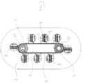
- FIG. 1 shows oval track 1 and a plurality of vehicles 3 that travel around the track.
- Vehicles 3 may be gondolas but other suitable vehicles for carrying one or more riders may be used in other embodiments.
- Movement mechanism 5 includes a main drive with one or more motors. Various suitable motors may be used. The motors may drive the rotational members 7.
- the main drive frame of movement mechanism 5 is coupled to the motors and in some embodiments, one rotational member 7 is fixed while the other rotational member 7 is positionally adjustable by jack bolts to properly tension the drive chain.
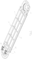
- FIG. 2 shows an embodiment of a layout of a movement mechanism 5 .
- FIG. 2 shows movement mechanism 5 with fixed bearing 15 and adjustable jack bearing 17. Movement mechanism 5 also includes frame 19 and chain guides 21. Bull sprockets 23 are associated with fixed bearing 15.
- movement mechanism 5 advantageously includes a chain, not shown in FIG. 1 , but which generally travels along trajectory 9.
- the chain connects movement mechanism 5 to the vehicles 3.
- the chain may be laterally constrained within a channel along trajectory 9 such as in chain guide 21 of FIG. 2 .
- Both a spring member 13 and the chassis frame 11, alternatively referred to as the trolley frame 11, are coupled to the chain of the movement mechanism 5.
- the chain runs horizontally and is coupled to vehicle 3 at connection point 29 of chassis frame 11 and a guide rod of a spring member 13 as will be seen more clearly in FIG. 3 .
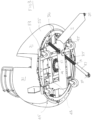
- FIG. 3 is a perspective view from beneath an exemplary vehicle such as vehicle 3 of FIG. 1 .
- the vehicle may be a gondola 31 that includes a lower chassis portion 53 and an upper rotatable carriage portion 55.
- FIG. 3 shows spring member 13 including inner spring portion 35 and an outer spring portion 36.
- Spring member 13 includes an internal guide rod disposed inside solid portion 37 and inside inner and outer spring portions 35, 36.
- a chain coupled to movement member 5 runs horizontally and is coupled to gondola 31 at connection point 29 of chassis frame 11 and at connection point 39 to the guide rod of spring member 13.
- Both the spring member 13 and the chassis frame 11, alternatively referred to as the trolley frame 11, are coupled to the chain of movement mechanism 5 at connection points 39, 29 respectively, which each may be spherical pivot connections to the chain.
- FIG. 3 also illustrates the main bearing 43 above which the rotatable carriage portion of the vehicle is completely and fully rotatable about a central vehicle axis 49.
- Caster wheels 45 are joined to chassis frame 11 which is part of lower chassis portion 53. In some embodiments, there is a rubber pad between caster wheels 45 and chassis frame 11 of lower chassis portion 53, such that caster wheels 45 are on rubber suspension to smooth out the ride.
- Spherical connection 51 includes vehicle axis 49 of rotation of gondola 31.
- vehicle 3 may be a two or four-person vehicle that travels along oval track 1 or an oval shaped track portion. Because movement mechanism 5, that imparts motion to vehicle 3, imparts motion to vehicle 3 at a steady speed, the vehicle experiences a whipping action when it reaches the ends of the oval portions such as at end portions 101 ( FIG. 1 ) because vehicle 3 speeds up to cover a greater length of track even though the chain is at a steady speed. In some embodiments a constant speed of movement mechanism 5 causes the vehicle 3 to accelerate when it approaches the ends of the oval sections. The whipping action induces the vehicle to accelerate and begin to rotate because the vehicle is completely rotational about its vertical axis 49.
- the spinning can continue as the vehicle travels along the straight sections of the track.
- the turning of the vehicle 3 causes more spinning and sometimes it causes the spinning to slow down depending on the physics such as rider configuration and the position of the seats going into the turn sections, i.e., ends of the oval shaped sections of the track.
- FIG. 4 presents a side view of vehicle 3 also shown in FIG. 3 .
- Vehicle 3 includes lower chassis portion 53 and upper rotatable carriage portion 55.
- the upper rotatable carriage portion 55 may include a plurality of seats for riders and in some embodiments will include two or four seats.
- Chassis portion 53 includes wheels 45 and is coupled to chain 57.
- Various suitable chains may be used and in one embodiment, the chain may include a minimum braking force of 360 kN. Chains of various sizes and using various types of modular links may be used in various embodiments. In one embodiment, the pitch of the chain links may be on the order of 200mm, but other chain pitches may be used in other embodiments.
- Wheels 45 travel along the surface of track 1.
- Carriage portion 55 is coupled to lower chassis portion 53 by way of bearing 43, more clearly shown in FIG. 3 , and is therefore rotatable about axis 49 and with respect to lower chassis portion 53.
- Chain 57 is part of movement mechanism 5 that travels along trajectory 9 of FIG.1 , and that imparts motion to vehicle 3 along track 1.
- FIG. 5 is another perspective view showing a section of gondola 31 of carriage portion 55 of vehicle 3.
- FIG. 5 shows chain 57 coupled to chassis frame 11 and also to solid portion 37 of spring member 13, via the indicated links at connection points 29 and 39 respectively.
- a parking brake may be electrically engaged at the conclusion of the ride when vehicle 3 is in the loading and unloading phase.
- the whipping action achieved at the ends of the oval portions of the track causes vehicle 3 to swing out to the side.
- Slider 41 is coupled to carriage portion 55 / gondola 31 such that the movement of slider 41 due to the spring force, moves carriage portion 55 / gondola 31.
- the spring member 13 expands to move slider 41, compressing outer spring portion 36 which responds by providing a restitution restoring force.
- the mechanism reaches an equilibrium during the whip, but the restoring force of the spring member 13 urges vehicle 3 back as the entire assembly of vehicle 3 reaches the straight section of track 1.
- the inner spring stabilizes the chassis portion 53 of vehicle 3 into its translational position along the track, before the next turn, while the rotatable carriage portion 55 remains rotatable about the central vehicle axis. Both the inner and outer springs have overtravel stops for redundancy.
- the disclosed invention finds application in various other arrangements that may use various other numbers of vehicles.
- the vehicles may include various arrangements of seats.
- two or four seats may be disposed side by side and in other embodiments, two or more seats may be disposed facing and across from two or more other seats or there may be 2 sets of seats arranged back-to-back.
- the vehicle may be a gondola with a single seat extending peripherally about a center of the gondola.
- various movement means may be used to move the chain coupled to the vehicle along the track at a suitable speed.
Landscapes
- Motorcycle And Bicycle Frame (AREA)
Applications Claiming Priority (1)
| Application Number | Priority Date | Filing Date | Title |
|---|---|---|---|
| US202363598218P | 2023-11-13 | 2023-11-13 |
Publications (1)
| Publication Number | Publication Date |
|---|---|
| EP4552714A1 true EP4552714A1 (de) | 2025-05-14 |
Family
ID=93521740
Family Applications (1)
| Application Number | Title | Priority Date | Filing Date |
|---|---|---|---|
| EP24212781.9A Withdrawn EP4552714A1 (de) | 2023-11-13 | 2024-11-13 | Vergnügungsfahrgeschäft |
Country Status (2)
| Country | Link |
|---|---|
| US (1) | US20250153057A1 (de) |
| EP (1) | EP4552714A1 (de) |
Citations (5)
| Publication number | Priority date | Publication date | Assignee | Title |
|---|---|---|---|---|
| US1128890A (en) | 1914-06-26 | 1915-02-16 | William Frederick Mangels | Amusement apparatus. |
| US1652975A (en) * | 1926-11-17 | 1927-12-13 | Frederick H Luff | Amusement device |
| GB281856A (en) * | 1926-11-17 | 1927-12-15 | Joseph Gilmour Davidson | Improvements in and relating to passenger carrying amusement devices of the endless track variety |
| DE202018106684U1 (de) * | 2018-11-23 | 2020-01-24 | Raw Tex International Establishment | Belustigungseinrichtung |
| EP4029583A1 (de) * | 2021-01-19 | 2022-07-20 | Willy Walser | Vergnügungsanlage für jahrmärkte, freizeitparks oder dergleichen |
-
2024
- 2024-11-12 US US18/945,265 patent/US20250153057A1/en active Pending
- 2024-11-13 EP EP24212781.9A patent/EP4552714A1/de not_active Withdrawn
Patent Citations (5)
| Publication number | Priority date | Publication date | Assignee | Title |
|---|---|---|---|---|
| US1128890A (en) | 1914-06-26 | 1915-02-16 | William Frederick Mangels | Amusement apparatus. |
| US1652975A (en) * | 1926-11-17 | 1927-12-13 | Frederick H Luff | Amusement device |
| GB281856A (en) * | 1926-11-17 | 1927-12-15 | Joseph Gilmour Davidson | Improvements in and relating to passenger carrying amusement devices of the endless track variety |
| DE202018106684U1 (de) * | 2018-11-23 | 2020-01-24 | Raw Tex International Establishment | Belustigungseinrichtung |
| EP4029583A1 (de) * | 2021-01-19 | 2022-07-20 | Willy Walser | Vergnügungsanlage für jahrmärkte, freizeitparks oder dergleichen |
Also Published As
| Publication number | Publication date |
|---|---|
| US20250153057A1 (en) | 2025-05-15 |
Similar Documents
| Publication | Publication Date | Title |
|---|---|---|
| US5433153A (en) | Amusement track ride system with helical spinning section having locking restraints and enhanced passenger view | |
| US8490550B2 (en) | Roller coaster with articulable seat backs | |
| US7610859B1 (en) | Carriage rotatable roller coaster tracks and vehicles | |
| JP2016537074A (ja) | タワー型乗り物用の軌道及び駆動部 | |
| CN109152959B (zh) | 用于使游乐设施的车辆的导轨系统的导轨部段移动的设备 | |
| CN1700944A (zh) | 大容量娱乐车 | |
| US4724771A (en) | Closed-loop amusement ride system | |
| JPH0673574B2 (ja) | 遊戯用軌道走行乗物装置の軌道構造 | |
| EP1364691B1 (de) | Amüsiervorrichtung und Verfahren zum Gebrauch der Amüsiervorrichtung | |
| US5115744A (en) | Extreme"G" accelerator amusement ride | |
| US4971314A (en) | Rotating disc amusement ride | |
| EP4552714A1 (de) | Vergnügungsfahrgeschäft | |
| US7784408B2 (en) | Ride | |
| US3403633A (en) | Amusement ride | |
| JP3439202B2 (ja) | 観覧車 | |
| US10576387B2 (en) | Amusement rides | |
| CA3136408C (en) | Amusement ride | |
| WO2004067126A1 (en) | Amusement ride | |
| JPS6348312Y2 (de) | ||
| WO2015070932A1 (en) | Amusement ride | |
| KR100320956B1 (ko) | 상부 타이어 마찰식 구조를 갖는 스윙식 놀이기구 | |
| DE19829625A1 (de) | Fahrgeschäft | |
| JP3767919B2 (ja) | 遊戯用乗物装置 | |
| JP3059026U (ja) | 乗物型の遊戯装置 | |
| JP3097759U (ja) | 給電用軌条を有する周回遊戯機 |
Legal Events
| Date | Code | Title | Description |
|---|---|---|---|
| PUAI | Public reference made under article 153(3) epc to a published international application that has entered the european phase |
Free format text: ORIGINAL CODE: 0009012 |
|
| STAA | Information on the status of an ep patent application or granted ep patent |
Free format text: STATUS: THE APPLICATION HAS BEEN PUBLISHED |
|
| AK | Designated contracting states |
Kind code of ref document: A1 Designated state(s): AL AT BE BG CH CY CZ DE DK EE ES FI FR GB GR HR HU IE IS IT LI LT LU LV MC ME MK MT NL NO PL PT RO RS SE SI SK SM TR |
|
| STAA | Information on the status of an ep patent application or granted ep patent |
Free format text: STATUS: THE APPLICATION IS DEEMED TO BE WITHDRAWN |
|
| 18D | Application deemed to be withdrawn |
Effective date: 20251115 |