EP4552717A1 - Vorrichtung zur trennung eines flüssigkeitssystems - Google Patents
Vorrichtung zur trennung eines flüssigkeitssystems Download PDFInfo
- Publication number
- EP4552717A1 EP4552717A1 EP23209508.3A EP23209508A EP4552717A1 EP 4552717 A1 EP4552717 A1 EP 4552717A1 EP 23209508 A EP23209508 A EP 23209508A EP 4552717 A1 EP4552717 A1 EP 4552717A1
- Authority
- EP
- European Patent Office
- Prior art keywords
- tank
- inlet
- debubbler
- liquid
- flow passage
- Prior art date
- Legal status (The legal status is an assumption and is not a legal conclusion. Google has not performed a legal analysis and makes no representation as to the accuracy of the status listed.)
- Pending
Links
Images

Classifications
-
- B—PERFORMING OPERATIONS; TRANSPORTING
- B01—PHYSICAL OR CHEMICAL PROCESSES OR APPARATUS IN GENERAL
- B01D—SEPARATION
- B01D19/00—Degasification of liquids
- B01D19/0042—Degasification of liquids modifying the liquid flow
-
- C—CHEMISTRY; METALLURGY
- C02—TREATMENT OF WATER, WASTE WATER, SEWAGE, OR SLUDGE
- C02F—TREATMENT OF WATER, WASTE WATER, SEWAGE, OR SLUDGE
- C02F1/00—Treatment of water, waste water, or sewage
- C02F1/20—Treatment of water, waste water, or sewage by degassing, i.e. liberation of dissolved gases
-
- C—CHEMISTRY; METALLURGY
- C02—TREATMENT OF WATER, WASTE WATER, SEWAGE, OR SLUDGE
- C02F—TREATMENT OF WATER, WASTE WATER, SEWAGE, OR SLUDGE
- C02F1/00—Treatment of water, waste water, or sewage
- C02F1/30—Treatment of water, waste water, or sewage by irradiation
- C02F1/32—Treatment of water, waste water, or sewage by irradiation with ultraviolet light
- C02F1/325—Irradiation devices or lamp constructions
-
- C—CHEMISTRY; METALLURGY
- C02—TREATMENT OF WATER, WASTE WATER, SEWAGE, OR SLUDGE
- C02F—TREATMENT OF WATER, WASTE WATER, SEWAGE, OR SLUDGE
- C02F2201/00—Apparatus for treatment of water, waste water or sewage
- C02F2201/32—Details relating to UV-irradiation devices
- C02F2201/322—Lamp arrangement
- C02F2201/3226—Units using UV-light emitting lasers
-
- C—CHEMISTRY; METALLURGY
- C02—TREATMENT OF WATER, WASTE WATER, SEWAGE, OR SLUDGE
- C02F—TREATMENT OF WATER, WASTE WATER, SEWAGE, OR SLUDGE
- C02F2303/00—Specific treatment goals
- C02F2303/04—Disinfection
Definitions
- the invention relates to a liquid system separation device (Issd).
- the liquid system separation device may comprise at least a tank having a tank volume being enclosed by a tank bottom, a tank cover and a tank sidewall connecting the tank bottom and the tank cover.
- a tank inlet may be in fluid communication with the tank volume and configured for being connected to a liquid providing system.
- a tank outlet may be in fluid communication with the tank volume and may be configured to be connected to a liquid receiving system.
- a debubbler may be located inside the tank and may be configured to receive liquid entering the tank via the inlet.
- a flow passage having a flow passage inlet may be configured to receive water from the debubbler and to provide a flow of the liquid via the flow passage towards the fluid outlet.
- a germ growth inhibiting radiation source with an enclosure may be being located between the tank cover and the debubbler.
- Backflow prevention systems are designed to ensure that water flows in one direction only, preventing the contamination of an upstream potable water supply with germs or other harm causing contaminants that might be present in a downstream water distribution system. This is critical, e.g., if there is a risk of backflow from a contaminated water distribution system, which could introduce contaminants into the potable water.
- Typical examples of such potentially contaminated water distribution systems are slaughterhouse connections, firefighting water supply systems, etc...
- liquid system separation devices have been suggested. These have a pressure tank with an inlet in a top portion and an outlet in the bottom portion. In operation, the pressure tank is partially filled, i.e., there is a water reservoir in the bottom portion of the tank. The water reservoir sources the outlet and is replenished with fresh water that pours from the inlet if water is withdrawn via the outlet. In between of the reservoir and the inlet is an air gap, preventing water being in contact with the tanks outlet from contacting the tank inlet. This measure significantly reduces the risk introducing contaminants from the water distribution system into the water supply system.
- UV light source An ultraviolet (UV) light source
- a liquid system separation device has been suggested in US-patent 11,053,669 B2 .
- it has been suggested to allow air bubbles to rise back into the air gap e.g., by installing a debubbler below the inlet.
- Some debubblers reduce the downward component of the flow speed of the water below the speed with which bubbles rise, thereby enabling bubbles to leave the liquid.
- the problem to be solved by the invention is to enhance operational safety of liquid systems that are arranged downstream of a liquid system separation device.
- a liquid system separation device may comprise at least a tank having a tank volume.
- the tank is preferably a pressure tank and may comprise a tank bottom, a tank cover and a tank sidewall connecting the tank bottom and the tank cover.
- the volume being enclosed by the tank bottom, the sidewall and the tank cover is the tank volume.
- the tank cover may as well be referred to as a tank top and is usually located opposite to the tank bottom.
- the tank may further comprise a tank inlet, being in fluid communication with the tank volume.
- the tank inlet may be configured for being coupled to a liquid supply system.
- the liquid supply system may be, e.g., a water supply system. In particular, it may be a potable water supply system.
- the liquid system separation device may comprise a tank outlet, being configured to be coupled to a liquid receiving system. Only to avoid misunderstandings, of course the tank inlet can be coupled to the liquid supply system and the tank outlet may be coupled to the liquid receiving system, but in practice, the liquid system separation device is preferably provided only with the respective inlet connector and/or outlet connector enabling to couple the liquid system separation device with a liquid supply system via the tank inlet and and/or with the downstream liquid receiving system via the tank outlet.
- potable water supply system includes the entire system of sourcing, treating, distributing, and delivering water that is safe for human consumption. It encompasses the infrastructure involved in providing potable water.
- coupling means that the tank inlet is or is configured to be in fluid communication via a corresponding connector (e.g., a fluid coupling) with a conduit of the potable water supply system that is configured to supply potable water.
- the tank outlet may be in fluid communication with the tank volume and may further be configured to be coupled to a liquid receiving system, for example a sprinkler system of a structure such as a building or any kind of machinery.
- the liquid receiving system further distributes the liquid and may hence as well be referred to as liquid distribution system.
- the tank may be a pressure tank.
- the term pressure tank shall express that other via the tank inlet or the tank outlet, the tank volume is not in fluid communication with the ambient atmosphere (under normal operating conditions, i.e., optional maintenance openings, optional pressure relief valves, etc. are assumed closed).
- the tank inlet is connected to a liquid supply system and the tank outlet is connected to a liquid receiving system, the tank provides for a pressure exchange between these two systems while the resulting pressure is at least essentially independent from ambient pressure.
- the liquid pressure provided by the liquid supply system propagates through the tank into the liquid receiving system.
- a debubbler may be located in the tank volume, i.e., inside the tank.
- the debubbler is preferably configured to receive a liquid entering the tank via the tank inlet, for example, via an air gap between the tank inlet and the debubbler.
- a debubbler is a device or system configured to remove or eliminate bubbles, specifically air bubbles or gas bubbles, from the liquid.
- the liquid system separation device may further comprise a flow passage having a flow passage inlet.
- the flow passage inlet is preferably configured to receive liquid (e.g., water) from the debubbler and to provide a flow of the liquid via the flow passage towards the tank outlet.
- a germ growth inhibiting radiation source may be located inside the tank volume and may have an enclosure. Typical enclosures are glass bulbs and/or glass tubes or other fragile germ growth inhibiting radiation transparent materials. Preferably, the germ growth inhibiting radiation source may be located between the tank cover and the debubbler. The germ growth inhibiting radiation source may preferably be configured to irradiate at least the tank inlet and/or the tank cover and/or the tank sidewall with germ growth inhibiting radiation. Many kind of germ growth inhibiting radiations are known, the most prominent example is electromagnetic radiation in the ultra-violet range, but as well ⁇ -radiation or x-ray may be used.
- a first mesh is located in the flow passage and/or in front of an intake of the flow passage and/or between the tank volume and the tank outlet.
- the first mesh may be configured to block fragments of glass or pieces of burst germ growth inhibiting radiation sources (hereinafter jointly light source fragments ) that may be inside the tank volume and thereby prevent these from entering the flow passage and hence from leaving the tank volume via the tank outlet.
- the downstream liquid receiving system remains free from light source fragments that can have a negative impact not only on sprinkler systems by clogging sprinkler openings, but as well liquid system in general as valves may be blocked and gaskets may be cut. In the food industry (slaughterhouse application), undetected light source fragments may even contaminate meat products and hence harm humans.
- a first shield is located above the flow passage inlet and extends over an outlet of the debubbler while not blocking, i.e., enabling a fluid communication between the debubbler and the flow passage inlet. This measure as well prevents light source fragments from entering the flow passage inlet.
- the first shield is hence preferably located between the at least one germ growth radiation source and the flow passage inlet.
- the shield may be a ring, extending from the tank sidewall inwards, while being located preferably above the flow passage inlet and while preferably being spaced from the flow passage inlet.
- the first shield may extend over a sidewall of debubbler, via which sidewall of the debubbler a liquid may flow into the flow passage inlet. This measure as well contributes to reduction of the risk that light source fragments may leave the tank volume via the tank outlet.
- Both examples i.e., the first mesh and the first shield, provide the same technical effect and are preferably combined, but each of these two measures may as well be used without the respective other measure.
- the invention is based on the observation that germ growth inhibiting radiation sources that are operated inside pressure tanks in a humid atmosphere require a radiation transmissive enclosure, for example a glass bulb or a glass tube or the like. These enclosures, however, have a limited life span and burst. It is assumed that these observed bursts are caused by pressure fluctuations inside the tank. The resulting light source fragments may enter the downstream liquid receiving system and cause harm there as explained above, e.g. clog sprinkler openings, valves, etc.. Operation of the downstream liquid receiving system remains ensured, even in case a burst bulb or tube remained unobserved and/or occurs during operation of the downstream liquid receiving.
- the debubbler comprises a liquid receiving pot with a pot opening facing towards the tank inlet.
- the debubbler opening (which may be the pot opening) is defined by a rim and enables access of fresh liquid pouring from the tank inlet into the pot opening. Excess liquid leaves the debubbler for example via the opening (and/or a debubbler outlet) and may simply pour over the sidewall or via a dedicated outlet opening into the flow passage. Light source fragments falling into the pot remain at the bottom and are hence retained.
- At least a portion of the flow passage may be located between the tank sidewall and the pot sidewall, as this arrangement allows a liquid flow, e.g. over the sidewall of the pot, into the flow passage.
- the liquid may flow via the flow passage into a liquid reservoir, being formed by the liquid (in operation) as explained in the prior art section.
- the technical teaching of US 2018 0155903 A1 is incorporated by reference herein as if fully disclosed.
- the term liquid reservoir encompasses both, as the liquid system separation device will be delivered without the liquid, which will be filled in the reservoir volume and thereby provide the reservoir.
- At least a section of the flow passage is formed by a gap extending between an outer surface of the pot sidewall and an inner surface of the tank sidewall, wherein the gap inlet is the flow passage inlet.
- This construction is safe and reduces the risk of new bubble formation as well as the risk that light source fragments enter the flow passage.
- the gap is a ring gap.
- the first mesh may form a ring and may be located in and/or on top of the flow passage inlet.
- This example has the advantage that a light source fragment that by chance comes to reside on the mesh may not block the entire flow passage. Further, light source fragments or other debris may not leave the tank volume, as these are retained by the first mesh.
- the liquid supply of a downstream liquid receiving system that may be sourced by the tank outlet is not reduced.
- the tank comprises a socket supporting a top portion of the germ growth inhibiting radiation source.
- the socket may be attached to the tank cover and/or the tank sidewall. Both measures allow to insert at least a lower portion of the germ growth inhibiting radiation source into the tank volume, while a top portion of the germ growth inhibiting radiation source may be supported in the socket. Connection lines of the germ growth inhibiting radiation source may extend, e.g., via a socket cap to a power supply and/or a control unit.
- the socket may comprise an outward facing surface, wherein outward references to the tank volume. The outward facing surface may support an inward facing surface of the top portion of the germ growth inhibiting light source.
- a gasket may be located between the outward facing surface of the socket and the inward facing surface of the top portion.
- the optional cap may extend over the top portion and press the downward facing surface against the up-facing surface, thereby sealing the tank preferably at least essentially gas tight (e.g. air tight).
- a first portion of the germ growth inhibiting radiation source 8 may be supported by the socket 18 relative to the tank.
- a bearing surface supports the free end of the germ growth inhibiting radiation source in at least a first direction, while allowing a translation of the free end in a second direction.
- the outward facing surface may be tubular.
- the bearing surface may support the (e.g., tubular) germ growth inhibiting light source perpendicular to the longitudinal axis of the germ growth inhibiting radiation source, while allowing for a translation of the free end of the germ growth inhibiting radiation source.
- the bearing surface may be considered as a linear bearing surface as it may allow for a translation of the free end of the germ growth inhibiting radiation source in the second direction, while blocking a translation of the free end of the germ growth inhibiting radiation source in the first direction.
- the first and the second direction are preferably orthogonal to each other.
- the second direction points towards the tank bottom and/or toward the first mesh.
- Both measures slow the lower portion down before it comes to a final abrupt stop. The risk of segmenting the lower portion of a fragmented germ growth inhibiting radiation source into a huge number of fragments is further reduced. This measure thus as well contributes to the effect of keeping the tank outlet clear of fragments while still allowing for large mesh size - which keeps pressure drop across in the liquid system separation device low.
- a second mesh may be located between the tank inlet and the tank volume and/or between the tank inlet and the debubbler. This second mesh provides two advantages, the gas bubbles are further reduced and in case a backflow occurs, solids being bigger than the mesh size can contaminate the upstream liquid supply system.
- the first mesh and/or the second mesh may preferably be configured to retain broken pieces of the enclosure of the germ growth inhibiting radiation source from entering the tank outlet and/or the tank inlet, respectively.
- the mesh essentially functions as a filter media and the mesh size has to be selected such that light source fragments of a size that may cause harm to the downstream liquid receiving system are retained by the mesh.
- the first mesh and the first shield are preferably combined to thereby have two independently operating light source fragment retention means, enhancing safety.
- a sidewall of the debubbler has at least one protrusion that extends into the flow passage, e.g., towards the tank sidewall.
- the tank sidewall may have at least one protrusion extending from the tank sidewall into the flow passage.
- an up-facing surface of the protrusion may support the first mesh. A portion of the first mesh may as well be located in the flow passage.
- the liquid system separation device may comprise a differential pressure sensor.
- the differential pressure sensor may have a first sensor inlet and a second sensor inlet.
- the first sensor inlet is preferably in fluid communication with a first portion of the tank volume above the first mesh and the second sensor inlet may be in fluid communication with a second portion of the tank volume, wherein the first portion of the tank volume and the second portion of the tank volume are separated by the first mesh.
- An increase in the pressure drop across the first mesh can be detected by a controller of the liquid system separation device. Such increase can be signaled to thereby trigger maintenance of the liquid system separation device.
- the signal can be indicative of a clogged first mesh and/or flow passage inlet.
- a preferred application of the liquid system separation device is structure, like e.g., a building having a water-based fire extinguishing media distribution system, e.g., a sprinkler system. Unless activated, the water-based fire extinguishing media distribution system is (hopefully) not regularly flushed and hence germs may populate the fire extinguishing media distribution system. If the water-based fire extinguishing media distribution system is coupled to the potable water net via the liquid system separation device, a contamination of the potable water net by germs residing in the fire extinguishing media distribution system can be excluded, further safe operation of the fire extinguishing media distribution system is not compromised by fragments of germ growth inhibiting light sources.
- a contamination of the potable water net by germs residing in the fire extinguishing media distribution system can be excluded, further safe operation of the fire extinguishing media distribution system is not compromised by fragments of germ growth inhibiting light sources.
- the structure such as a building, may comprise the above-described liquid system separation device, and the tank inlet is preferably coupled to the potable water grid of the structure, which grid may as well be referred to as plumbing of the structure.
- the tank outlet may preferably be coupled to a water inlet of the fire extinguishing media distribution system.
- the invention has been described with reference to any liquid that has to be delivered from a liquid supply system to a liquid receiving system.
- Water is only a preferred example, but the principle of the invention is not limited to water.
- gasoline tanks of aircraft or ships often suffer from germ contamination.
- the liquid system separation device may as well be used either cultivated of the vessel and/or integrated in the gas station.
- the tank inlet may be coupled to a supply pipeline connecting the tank inlet with a fuel reservoir and the tank outlet may be coupled to a fuel hose, thereby preventing contamination of the fuel reservoir. Similar problems are known in the food industry, the chemical industry and pharmaceutical industry and these may as well be solved by the liquid system separation device.
- the directions “upward” and “downward” indicate a vector pointing parallel to the tank wall from the tank bottom to the tank cover and from the tank cover to the tank bottom, respectively.
- the tank cover and the tank bottom reference to the orientation of the liquid system separation device during normal operating conditions, hence the gravity vector points from the tank cover towards the tank bottom, assuming the tank wall extends at least essentially vertically.
- two fluid transportation means like e.g., a tube, a conduit, etc.
- storage means such as a tank
- the fluid communication may be blocked by a valve, but is generally possible (if the valve is open).
- a pure attachment of these means would provide an adherence of the two parts, but not enable said fluid communication.
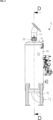
- FIG. 1 shows two first examples 1 of a liquid system separation device 1.
- the number two can be altered between 1 and any other natural number, as required, but two is a preferred example as it provides for a redundancy in case one of the two liquid system separation devices is blocked or for another reason out of order.
- the liquid system separation devices 1 may each have a tank 10 with a tank inlet 17 and a tank outlet 13.
- the tank inlets 17 may be connected to a conduit of a liquid supply system 110, which in the present case can be, e.g., a potable water grid of a building or any other kind of structure.
- the tank outlets 13 may be connected to a conduit of a liquid receiving system 120, like e.g., a sprinkler system of the structure.
- the liquid supply system 110 and the liquid receiving system 120 are each part of the structure and shall be considered to represent such structure that comprises at least one of these as pars pro toto.
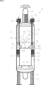
- the first liquid system separation device 1 has a tank 10 with a tank bottom 12, a tank sidewall 14 and a tank cover 16 as well referred to as tank top 16 that jointly enclose and hence define a tank volume 11.
- the tank cover 16 may have a tank inlet 17 and the tank bottom 12 may have a tank outlet 13.
- the tank inlet 17 may be configured to be coupled to the conduit of the liquid supply system 120 (see FIG. 1 ) and the tank outlet 13 may be configured to be coupled to conduit of a liquid receiving system, like, e.g., a fire extinguishing media distribution system (see FIG. 1 ).
- the debubbler 20 may be considered as a receiving pot and the debubbler may comprise a debubbler bottom 22 and debubbler sidewall 24 defining a debubbler opening 25.
- a fluid entering the tank volume 11 via the tank inlet 17 from the top may pour into the debubbler 20 via e.g., a center portion of the debubbler opening 25. Bubbles may rise and excess liquid may flow over the up-facing surface 241 of the debubbler sidewall 24.
- the up-facing surface 241 may as well be referred to as tank cover 16 facing surface 241 and may be considered as the debubbler outlet 241, but other debubbler outlets 241 can be used as well (e.g. one or more through holes in the debubbler sidewall 24).
- a flow passage 30 connecting the debubbler outlet 241 with the tank outlet via a liquid reservoir 40 that is filled when operating the liquid system separation device 1.
- the liquid reservoir 40 is indicated by a liquid level 40, to render it vivid.
- An upper portion of the flow passage 30 may form a ring gap 37 and define a flow passage inlet 37.
- one or more germ growth inhibiting radiation sources 8, such as an ultraviolet (UV) light emitting tubes 8 may be located in the tank volume 11 below the tank cover 16 and above the debubbler opening.
- a gas e.g., air
- the germ growth inhibiting radiation sources 8 may hence be configured to irradiate at least the boundary of the tank inlet 17 and/or a ring surface enclosing the tank inlet 17.
- the one or more germ growth inhibiting radiation sources 8 have a top portion that may extend through a socket 18 being attached to the tank cover 16. As shown, the socket 18 may provide an outward facing surface supporting an inward facing surface of the top portion. A gasket may be located between the up-facing surface of the socket 18 and the downward facing surface of the top portion. A cap may extend over the top portion and press the downward facing surface against the up-facing surface, thereby sealing the tank preferably at least essentially gas tight (e.g. air tight). Generally, the support provided by the socket 18 is more than sufficient to position the germ growth inhibiting radiation sources 8 in the tank volume 11.
- the free ends of the germ growth inhibiting radiation sources 8 are each supported by at least one plain bearing surface 81 enabling a movement of the free end along the axis of the respective germ growth inhibiting radiation source 8, while supporting the free end in at least one of the radial directions.
- the free ends of the germ growth inhibiting radiation sources 8 may hence slide over the respective plain bearing surfaces and thus form a linear bearing allowing for a translation of the free ends of the germ growth inhibiting radiation sources 8 relative to the tank cover.
- the plain bearing surface 81 is the inner surface of a sleeve 80 being attached (at least indirectly) to the tank 10.
- the free ends of the germ growth inhibiting radiation sources 8 may each extend into a sleeve 80 being oriented at least essentially parallel to the longitudinal axis of the respective germ growth inhibiting radiation source 8. , wherein sleeve radially supports the free end of the germ growth inhibiting radiation sources 8.
- the sleeves 80 may have openings, e.g. slits or any other kind of through hole and/or be entirely transparent for the germ growth inhibiting radiation may be emitted by the germ growth inhibiting radiation sources 8.
- the optional sleeves 80 further reduce the number of fragments, in case a germ growth inhibiting radiation source 8 breaks: It has been observed that in case a germ growth inhibiting radiation source breaks, the lower portion, i.e. the portion below the break or crack simply falls down. In the depicted example this portion slides down the sleeves without falling to the side, thereby avoiding that the lower portion of the broken germ growth inhibiting radiation source splitters in a huge number of small fragments. It is particularly preferred if the lower ends of the sleeves are open and preferably configured to be below the liquid level 40 that remains during operation on the tank bottom 12. In addition or alternatively, it is preferred, if the lower ends of the sleeves 80 are located above the first mesh 50. Both measures further reduce the risk of a huge number of fragments, as these jointly contribute to the effect of slowing the lower portion sliding down slowly, i.e. not abruptly.
- a first mesh 50 may be located above and/or in the flow passage 30, e.g. in inlet section of the flow passage 30.
- the first mesh 50 may extend above the debubbler outlet, radially and/or axially (with reference to the vertical axis 2 of the tank 10) while not blocking a fluid communication between the debubbler 20 and the flow passage inlet 37, thereby providing for an additional protection of the flow passage inlet 37, as at least some radiation source fragments falling on the first mesh 50 may slide off the first mesh into the debubbler, i.e. finally these will accumulate on the debubbler bottom 22.
- the first mesh 50 may be supported on protrusions 29 that may extend from the debubbler sidewall 24 into the flow passage.
- fragments of the germ growth inhibiting radiation sources 8 will be retained by the first mesh and may hence not be transported by the liquid flow via the tank outlet 13 into a liquid receiving system that may preferably be attached to the tank outlet 13 of the liquid system separation device 1.
- an optional first shield 60 may be located above the flow passage inlet 37 and extend over the outlet 241 of the debubbler 24 while not blocking a fluid communication between the debubbler 20 and the flow passage inlet 37.
- the optional first shield 60 as well prevents radiation source fragments from entering the flow passage inlet 37.
- the first shield 60 may hence preferably be located between below the at least one germ growth inhibiting radiation source 8 and the flow passage inlet 37.
- the first shield 60 may be a ring having a ring opening 65 being located below the tank inlet 17 and above the opening 25 of the debubbler.
- the first shield is preferably configured to provide a direct path for a liquid flowing out of the tank inlet 17 into the tank volume into the debubbler opening 25, e.g. via said ring opening 65.
- the outer edge of the first shield 60 may be located above the inner ring surface 64 which delimits the first shield towards the ring opening 65. In this sense, the shield may be frustrated cone, but other shapes are possible as well.
- the first shield 60 may preferably extend from the tank sidewall 14 inwards above the flow passage inlet 37, while being spaced from the flow passage inlet 37 vertically. In other words, a vertical projection of the inner rim of the first shield 60 may preferably be more inward than the up-facing surface 241 of the debubbler sidewall 24. Further, a ray 90 from any point of the germ growth inhibiting radiation sources 8 towards the inlet 37 of the flow passage 30 is blocked by the first shield 60. This provides the advantage that no fragment of a potentially bursting germ growth inhibiting radiation source 8 may reach the inlet 37 of the flow passage 30. Like in the depicted example, the first shield 60 may extend over the debubbler sidewall 24 and hence over the debubbler outlet 241 being defined in this example by the up-facing surface 241 of the debubbler sidewall 24.
- the first shield 60 has been shown together with the first mesh 50, which is considered as a preferred example, but in particular if the liquid system separation system 1 has a first shield 60, the first mesh 50 can be omitted and vice versa.
Landscapes
- Chemical & Material Sciences (AREA)
- Life Sciences & Earth Sciences (AREA)
- Hydrology & Water Resources (AREA)
- Engineering & Computer Science (AREA)
- Environmental & Geological Engineering (AREA)
- Water Supply & Treatment (AREA)
- Organic Chemistry (AREA)
- Health & Medical Sciences (AREA)
- Toxicology (AREA)
- Chemical Kinetics & Catalysis (AREA)
- Physical Water Treatments (AREA)
Priority Applications (1)
| Application Number | Priority Date | Filing Date | Title |
|---|---|---|---|
| EP23209508.3A EP4552717A1 (de) | 2023-11-13 | 2023-11-13 | Vorrichtung zur trennung eines flüssigkeitssystems |
Applications Claiming Priority (1)
| Application Number | Priority Date | Filing Date | Title |
|---|---|---|---|
| EP23209508.3A EP4552717A1 (de) | 2023-11-13 | 2023-11-13 | Vorrichtung zur trennung eines flüssigkeitssystems |
Publications (1)
| Publication Number | Publication Date |
|---|---|
| EP4552717A1 true EP4552717A1 (de) | 2025-05-14 |
Family
ID=88833635
Family Applications (1)
| Application Number | Title | Priority Date | Filing Date |
|---|---|---|---|
| EP23209508.3A Pending EP4552717A1 (de) | 2023-11-13 | 2023-11-13 | Vorrichtung zur trennung eines flüssigkeitssystems |
Country Status (1)
| Country | Link |
|---|---|
| EP (1) | EP4552717A1 (de) |
Citations (8)
| Publication number | Priority date | Publication date | Assignee | Title |
|---|---|---|---|---|
| JPH07124555A (ja) * | 1993-11-04 | 1995-05-16 | Takeshi Fukuyama | 水の浄水活性化方法および浄水活性化装置 |
| RU2057548C1 (ru) * | 1994-12-26 | 1996-04-10 | Акционерное общество открытого типа Холдинговая компания "Гранит-Саламандра" | Установка для обеззараживания жидкости |
| US6447721B1 (en) * | 2000-07-31 | 2002-09-10 | Remotelight, Inc. | Drinking water UV disinfection system and method |
| JP2003212754A (ja) * | 2001-03-09 | 2003-07-30 | National Institute Of Advanced Industrial & Technology | 入浴剤組成物 |
| WO2009063737A1 (ja) * | 2007-11-15 | 2009-05-22 | Ube Industries, Ltd. | 水浄化装置及び水浄化方法 |
| WO2011032543A2 (de) * | 2009-09-18 | 2011-03-24 | Alexander Schluttig | Selbstdesinfizierender geruchsverschluss |
| EP2540673A1 (de) * | 2010-02-24 | 2013-01-02 | Ube Industries, Ltd. | Vorrichtung zur ultraviolett-oxidation, vorrichtung zur herstellung von ultrareinem wasser, verahren zur ultraviolett-oxidation und verfahren zur herstellung von ultrareinem wasser |
| US20180155903A1 (en) | 2015-08-04 | 2018-06-07 | Reinhard Völk | System separation device |
-
2023
- 2023-11-13 EP EP23209508.3A patent/EP4552717A1/de active Pending
Patent Citations (9)
| Publication number | Priority date | Publication date | Assignee | Title |
|---|---|---|---|---|
| JPH07124555A (ja) * | 1993-11-04 | 1995-05-16 | Takeshi Fukuyama | 水の浄水活性化方法および浄水活性化装置 |
| RU2057548C1 (ru) * | 1994-12-26 | 1996-04-10 | Акционерное общество открытого типа Холдинговая компания "Гранит-Саламандра" | Установка для обеззараживания жидкости |
| US6447721B1 (en) * | 2000-07-31 | 2002-09-10 | Remotelight, Inc. | Drinking water UV disinfection system and method |
| JP2003212754A (ja) * | 2001-03-09 | 2003-07-30 | National Institute Of Advanced Industrial & Technology | 入浴剤組成物 |
| WO2009063737A1 (ja) * | 2007-11-15 | 2009-05-22 | Ube Industries, Ltd. | 水浄化装置及び水浄化方法 |
| WO2011032543A2 (de) * | 2009-09-18 | 2011-03-24 | Alexander Schluttig | Selbstdesinfizierender geruchsverschluss |
| EP2540673A1 (de) * | 2010-02-24 | 2013-01-02 | Ube Industries, Ltd. | Vorrichtung zur ultraviolett-oxidation, vorrichtung zur herstellung von ultrareinem wasser, verahren zur ultraviolett-oxidation und verfahren zur herstellung von ultrareinem wasser |
| US20180155903A1 (en) | 2015-08-04 | 2018-06-07 | Reinhard Völk | System separation device |
| US11053669B2 (en) | 2015-08-04 | 2021-07-06 | Reinhard Völk | System separation device |
Similar Documents
| Publication | Publication Date | Title |
|---|---|---|
| RU2476252C2 (ru) | Устройство, системы и способы противопожарной защиты для воздействия на пожар посредством тумана | |
| US5613513A (en) | Liquid flow control device | |
| BRPI0910208B8 (pt) | umidificador em linha, e umidificador em linha com múltiplos lados | |
| PT754071E (pt) | Sistema de enchimento de vaporizador de anestesico | |
| US20070125960A1 (en) | Ultraviolet sterilizer with a double-chamber structure | |
| EP4552717A1 (de) | Vorrichtung zur trennung eines flüssigkeitssystems | |
| GB2450086A (en) | Central heating systems | |
| KR20180065136A (ko) | 벤트 라인 화염 차단 장치 | |
| US20160298779A1 (en) | Auxiliary flow prevention mechanism for an air valve in a pipeline | |
| US20210293351A1 (en) | Tank level sensor | |
| US20160370004A1 (en) | Fire-on-Water Gas Burner | |
| US20090291036A1 (en) | UV Sterilizer for Fluid of Large Flow Rate | |
| CA2589842A1 (en) | Universal fluid valve body | |
| US8298309B2 (en) | Liquid separator and tank system comprising a liquid separator | |
| CN212251683U (zh) | 一种防泄漏天然气管道 | |
| RU2566359C2 (ru) | Смотровой канал стравливания давления регулирующего клапана | |
| JP2009293525A (ja) | 推薬タンクのフィルタ装置 | |
| CN105805365A (zh) | 减压式倒流防止器 | |
| CN219796115U (zh) | 一种自塞式阻流阀 | |
| JP5031757B2 (ja) | パイプ分岐装置 | |
| KR101138328B1 (ko) | 발라스트 수 유도용 격벽을 갖는 자외선 살균 챔버 | |
| CN114195219B (zh) | 杀菌装置 | |
| KR20030029651A (ko) | 원자로 플랜트 | |
| SE506292C2 (sv) | Anordning vid en byggnad för motverkande av spridning av brand och/eller brandgaser | |
| JP6742896B2 (ja) | 原子力発電所用溢水排水設備 |
Legal Events
| Date | Code | Title | Description |
|---|---|---|---|
| PUAI | Public reference made under article 153(3) epc to a published international application that has entered the european phase |
Free format text: ORIGINAL CODE: 0009012 |
|
| STAA | Information on the status of an ep patent application or granted ep patent |
Free format text: STATUS: THE APPLICATION HAS BEEN PUBLISHED |
|
| AK | Designated contracting states |
Kind code of ref document: A1 Designated state(s): AL AT BE BG CH CY CZ DE DK EE ES FI FR GB GR HR HU IE IS IT LI LT LU LV MC ME MK MT NL NO PL PT RO RS SE SI SK SM TR |
|
| STAA | Information on the status of an ep patent application or granted ep patent |
Free format text: STATUS: REQUEST FOR EXAMINATION WAS MADE |
|
| STAA | Information on the status of an ep patent application or granted ep patent |
Free format text: STATUS: EXAMINATION IS IN PROGRESS |
|
| 17P | Request for examination filed |
Effective date: 20250611 |
|
| 17Q | First examination report despatched |
Effective date: 20250707 |
|
| GRAP | Despatch of communication of intention to grant a patent |
Free format text: ORIGINAL CODE: EPIDOSNIGR1 |
|
| STAA | Information on the status of an ep patent application or granted ep patent |
Free format text: STATUS: GRANT OF PATENT IS INTENDED |
|
| INTG | Intention to grant announced |
Effective date: 20260105 |
|
| GRAS | Grant fee paid |
Free format text: ORIGINAL CODE: EPIDOSNIGR3 |