EP4552767A1 - Lingotière de tuyaux - Google Patents
Lingotière de tuyaux Download PDFInfo
- Publication number
- EP4552767A1 EP4552767A1 EP24208908.4A EP24208908A EP4552767A1 EP 4552767 A1 EP4552767 A1 EP 4552767A1 EP 24208908 A EP24208908 A EP 24208908A EP 4552767 A1 EP4552767 A1 EP 4552767A1
- Authority
- EP
- European Patent Office
- Prior art keywords
- tubular mold
- mandrel
- tubular
- mold
- hollow body
- Prior art date
- Legal status (The legal status is an assumption and is not a legal conclusion. Google has not performed a legal analysis and makes no representation as to the accuracy of the status listed.)
- Pending
Links
Images


Classifications
-
- B—PERFORMING OPERATIONS; TRANSPORTING
- B22—CASTING; POWDER METALLURGY
- B22D—CASTING OF METALS; CASTING OF OTHER SUBSTANCES BY THE SAME PROCESSES OR DEVICES
- B22D11/00—Continuous casting of metals, i.e. casting in indefinite lengths
- B22D11/006—Continuous casting of metals, i.e. casting in indefinite lengths of tubes
-
- B—PERFORMING OPERATIONS; TRANSPORTING
- B22—CASTING; POWDER METALLURGY
- B22D—CASTING OF METALS; CASTING OF OTHER SUBSTANCES BY THE SAME PROCESSES OR DEVICES
- B22D11/00—Continuous casting of metals, i.e. casting in indefinite lengths
- B22D11/04—Continuous casting of metals, i.e. casting in indefinite lengths into open-ended moulds
- B22D11/0406—Moulds with special profile
-
- B—PERFORMING OPERATIONS; TRANSPORTING
- B22—CASTING; POWDER METALLURGY
- B22D—CASTING OF METALS; CASTING OF OTHER SUBSTANCES BY THE SAME PROCESSES OR DEVICES
- B22D11/00—Continuous casting of metals, i.e. casting in indefinite lengths
- B22D11/04—Continuous casting of metals, i.e. casting in indefinite lengths into open-ended moulds
- B22D11/057—Manufacturing or calibrating the moulds
Definitions
- the invention relates to a tubular mold for producing a metal tubular strand in a continuous casting plant. Furthermore, the invention relates to methods for casting the tubular strand.
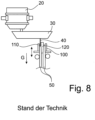
- Figure 8 shows the structure of a classic tubular mold 100, as it has traditionally been used to produce pipe strands. It essentially consists of a tubular mold hollow body 110 with a mandrel 120 projecting into it for casting the pipe strand 50. The casting direction is designated by the reference symbol G.
- the tubular mold 100 is filled with molten metal to cast the pipe strand. The molten metal is initially held in a ladle 20, is directed from the ladle into an intermediate container 30, and is finally directed from the intermediate container into the tubular mold 100 via a dip tube 40 to the side of the mandrel 120.
- German Auslegeschrift 1136797 discloses a tubular mold according to the preamble of patent claim 1 for producing a metal tubular strand in a continuous casting plant.
- the tubular mold disclosed therein comprises a hollow tubular mold body with an upper pouring area for a molten metal and a lower outlet area for the tubular strand.
- the pouring area of the tubular mold is widened compared to the inner diameter of the tubular mold hollow body, which corresponds to the outer diameter of the tubular strand to be cast.
- a mandrel extends into the pouring area of the tubular mold hollow body, which has internal cooling and can perform an eccentric movement.
- the invention is based on the object of further developing a known tubular mold with an already expanded pouring area in such a way that the pouring of molten metal is further facilitated. Furthermore, the object of the invention is to further develop known methods for casting a tubular strand in such a way that the production of the tubular strand in the mold is improved.
- the guiding idea of the invention is not the pouring of molten metal into an elliptical mold, but pouring into an enlarged annular gap between two molds, ie between the tubular mold hollow body and the mandrel in their respective claimed designs. This double widening is created by rotating the two ellipses against each other. The angle ⁇ is measured, for example, between the two main axes of the two ellipses.
- the expanded pouring area for the molten metal according to the invention advantageously enables safe and facilitated pouring of the molten metal into the tubular mold.
- This advantageously allows tubular strands with thinner wall thicknesses to be continuously cast than was possible in the prior art.
- the claimed, preferably double-elliptical design of the pouring area advantageously enables the immersion of one or even two immersion tubes, since the claimed formation of a single ellipse or the claimed rotation of the two ellipses relative to one another at two points enlarges the pouring area.
- the pouring area is tapered or narrowed. In other words: the distance between the inner mandrel and the outer mold is increased, thereby forming the locally expanded pouring area.
- metal refers in particular to steel, but also includes non-ferrous metals such as aluminum, lead, copper, nickel, tin and zinc, etc., as well as alloys of these metals.
- pipe string means a cast string in the form of a pipe.
- elliptical represents any two-dimensional geometric shape that is longer in one longitudinal direction than in the transverse direction. Examples include rectangles and egg-shaped outlines. The term is not limited to its strict mathematical definition.
- continuous means the casting of a theoretically endless strand, or that the continuous casting plant is designed accordingly; in particular, the length of the strand is not limited by the configuration of the continuous casting plant.
- semi-continuous means the casting of a strand whose length is limited by the configuration of the continuous casting plant.
- the claimed tube mold advantageously enables the production of tube strands in a continuous casting operation using the said continuous casting plant.
- the claimed tube mold is advantageous compared to the prior art in terms of both economic efficiency and the quality of the cast tube strands.
- the inner contour of the hollow tube mold body in its exit area forms the outer contour of the cast tube string.
- the outer contour of the mandrel at its largest circumference determines the inner contour and, in particular, the inner diameter of the cast tube string.
- a concentric shape of the inner contour of the hollow tubular mould body in its Outlet region and the outer contour of the mandrel at its end facing the outlet region of the tubular mold hollow body it is advantageous that the wall thickness of the pipe strand is uniform in the circumferential direction. This applies even though the wall thickness of the pipe strand in the pouring region of the tubular mold hollow body is not constant due to the claimed design with the different ellipses on the outside of the mandrel and the inside of the tubular mold hollow body.
- the uniform wall thickness applies to any annular cross-section of the annular gap or pipe strand in the outlet region of the tubular mold.
- the uniform distribution of the wall thickness in the circumferential direction can be realized in particular for a circular-concentric design of the said inner contour and the said outer contour relative to one another in the outlet region as well as for elliptical-concentric design of the said inner contour and the said outer contour relative to one another.
- the deformation of the tube strand takes place over the length of the mold from a cross-section formed by the two ellipses rotated against each other to a cross-section formed, for example, by two concentric circles, whereby this deformation follows the shrinkage due to cooling of the two (inner and outer) strand shells.
- a first cooling circuit is provided for cooling the mandrel internally.
- the thus cooled mandrel absorbs heat from the surrounding tubing.
- the temperature difference between the inner surface/strand shell of the cast tubing and the outer surface of the cooled mandrel enables sufficiently effective heat dissipation from the inner (strand) surface of the cast tubing to the cooled mandrel by means of heat conduction and radiation.
- a second cooling circuit for cooling the optionally present at least one heat sink.
- the cooled surface of the The heat sink contributes to the desired cooling and solidification of the cast tubing strand on its inner surface/strand shell. In combination with the cooled mandrel, its cooling effect is enhanced.
- the first and second cooling circuits can, but do not have to, be operated simultaneously.
- the first and second cooling circuits can be one and the same cooling circuit, through which a single cooling medium flows.
- the cooling channels in the mandrel and, if applicable, in the at least one heat sink are then fluidly connected to one another.
- the at least one heat sink is preferably attached fixedly or movably to the lower end of the mandrel and in this respect represents an optional mandrel extension.
- the maximum outer diameter of the heat sink is less than or equal to the outer diameter of the mandrel at its end facing the outlet of the tubular mold, i.e. preferably less than the inner diameter of the tubing to be cast. Due to the said relationship of the outer diameters, in particular a largely contactless cooling of the cast tubing in its interior by the heat sink is made possible.
- the mandrel and/or the heat sink attached to the mandrel is preferably conical with a tapered end.
- the conical heat sink is attached to the lower end of the mandrel in such a way that the wider end of the conical heat sink points toward the exit area of the tubular mold, because in this example the heat sink extends beyond the exit area of the mold in the casting direction.
- Several heat sinks can be hung one behind the other in the form of a chain. The chain can then be attached to the lower end of the mandrel, i.e., the end facing the exit area of the tubular mold hollow body.
- the said conical design of the mandrel and/or the attached heat sink advantageously creates a gap between the strand shell on the inner surface of the cast tubular strand and the heat sink or mandrel.
- This gap can advantageously be flooded with a protective gas, e.g. nitrogen or a noble gas such as argon or helium, which advantageously only reduces oxidation.
- a protective gas e.g. nitrogen or a noble gas such as argon or helium, which advantageously only reduces oxidation.
- a continuous line for the protective gas is formed in the mandrel and preferably also in the heat sink, which line can be connected to a protective gas source.
- At least one outlet opening for the protective gas to escape into the said gap, in particular an annular gap, is formed in the mandrel and/or in the heat sink.
- the mandrel and/or the at least one heat sink is coated with graphite on its exterior to ensure a type of emergency running property or lubrication upon contact with the inner strand shell of the cast tubing.
- Such a coating can minimize the gap between the inner strand shell and the heat sink and, if necessary, eliminate it.
- the two oscillation devices preferably operate independently of one another. This is advantageous because the lubrication conditions between the outside of the tubular strand to be cast and the inside of the hollow tubular mold body (first contact surface), on the one hand, and between the inside of the tubular strand to be cast and the outer surface of the mandrel (second contact surface), on the other hand, can be very different.
- the lubrication conditions on both contact surfaces are essentially determined by the added casting powder or casting oil; however, due to different flow conditions of the molten metal at both contact surfaces, the lubrication conditions there can - as already mentioned - be very different.
- the preferably independent oscillations of the mandrel and the hollow tubular mold body according to the invention make it possible to individually adapt the parameters of the oscillations to the lubrication conditions on or in the respective contact surfaces and thus to realize overall optimized conditions for the strand lubrication.
- the oscillation parameters for the hollow tubular mold body and the mandrel can be, for example, the stroke, i.e., the amplitude, the frequency, or the oscillation shape. According to the invention, these oscillation parameters can be adjusted independently of one another for the mandrel and the mold to optimize the lubrication conditions in the respective contact surfaces. A phase shift between the hollow body oscillation and the mandrel oscillation is also conceivable. Likewise, the mandrel oscillation can, for example, be paused and the mold oscillation continued, and vice versa. This allows a further degree of freedom for various casting process situations, such as during pouring or the start of casting, during so-called composite casting or the controlled end of casting, as well as in the event of malfunctions. For this purpose, the mandrel oscillation is preferably designed completely independently of the hollow body oscillation in terms of drive technology, control or regulation, and mechanical guidance.
- the hollow body of the tubular mold has an inner diameter of at least 350 mm in its exit region. This enables the casting of a tubular strand with an outer diameter of at least 350 mm.
- outer diameters of this size and larger offer the advantage that, even with relatively thin wall thicknesses, sufficient productivity for industrial production can be ensured.
- the relatively large outer diameter, combined with a relatively thin wall thickness of, for example, 50 mm, ensures that the cast tubular strand has only a relatively short metallurgical length, even at high casting speeds. This relatively short metallurgical length and the resulting limited mandrel length reduce system complexity and enable reliable hollow casting.
- the ratio of the inner diameter of the hollow mold body, i.e. the outer diameter of the cast pipe strand, to the radial distance between the inside of the hollow mold body and the outside of the mandrel, i.e. to the wall thickness of the cast pipe strand, in the outlet region of the pipe mold is in a range between 1:4 and 1:25, preferably between 1:8 and 1:12.
- This enables the casting of a pipe strand with a ratio of outer diameter to wall thickness between 1:4 and 1:25, preferably 1:8 to 1:12. This has the advantage that a sufficient wall thickness from the casting process is still available for any forming in a subsequent rolling process.
- the continuous casting plant with the tubular mold according to the invention for casting a pipe strand can be either a purely vertical plant, in which the pipe strand is guided vertically until it solidifies, or an arc-shaped continuous casting plant.
- the Figure 1 shows a tube mold 100 according to the present invention for producing a tube strand 50 made of metal in a continuous casting plant, as described in the introduction with reference to Figure 7 was described.
- the tubular mold 100 consists of a tubular mold hollow body 110 with an annular cross-section over its entire height. It has an upper pouring area 112 for pouring in a molten metal and a lower outlet area 114 for the freshly cast and not yet fully solidified tubular strand 50.
- the tubular mold 100 has at least one mandrel 120 projecting into the pouring area 112. Between the inner side of the tubular mold hollow body 110 and the outer surface of the mandrel 120, an annular gap is formed in which the tubular strand to be cast forms when filled with molten metal.
- the annular gap and the tubular strand are denoted equally by the reference numeral 50.
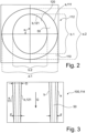
- Figure 2 shows a cross-section through the pouring area 112 of the tubular mold hollow body 110 transversely to the casting direction G.
- the inner contour of the annular cross-section of the tubular mold hollow body 110 - and thus the outer boundary of the annular gap 50 - is designed in the form of a first ellipse and designated by the reference symbol a.
- the outer contour of the mandrel 120, at its location with the largest diameter in the pouring area 112, is designed according to the invention in the form of a second ellipse and designated by the reference symbol b.
- the annular gap 50 for pouring in the molten metal is located between the contours a, b.
- the inner contour of the tubular mold hollow body 110 forms the outer boundary of the annular gap or the pouring area 112.
- the outer contour of the cross-section through the mandrel 120 at its location with the largest diameter forms the inner boundary of the annular gap.
- the poured metal melt solidifies progressively in the casting direction G and thus the desired pipe strand is formed with the strand shells on its outside and inside.
- Fig. 2 each designated by a reference symbol.
- the major axis of the first ellipse a is designated by the reference symbol a.1 and its minor axis by the reference symbol a.2; the following applies: a.1 > a.2.
- the major axis of the smaller second ellipse b is designated by the reference symbol b.1 and its minor axis by b.2; the following applies: b.1 > b.2.
- the two ellipses a and b are also rotated relative to one another by the angle ⁇ .
- the minor axis a.2 of the larger first ellipse a is larger than the major axis b.1 of the second ellipse b.
- the freshly cast tubular strand 50 undergoes a shrinkage of approximately 1% in its circumferential length.
- the geometry of the tubular mold 100 accommodates this, as its inner surface tapers in the casting direction G from the pouring area 112 to the exit area 114 of the tubular mold, following the shrinkage of the increasingly solidifying metal; see the longitudinal section through the tubular mold 100 according to Figure 3
- the exact shrinkage and the local distribution of shrinkage over the length of the mold depends on the casting conditions and the steel grade.
- the inner contour 111 of the hollow tubular mold body 110 changes in the casting direction G not only for the purpose of adapting to the shrinking metal, but also for the purpose of achieving a preferably constant distribution of the wall thickness d of the tubular strand 50 in the circumferential direction with a desired geometric cross-sectional shape of the tubular strand 50 in the outlet region 114 of the hollow tubular mold body 110.
- the inner contour 111 of the tubular mold hollow body 110 continuously transitions from its elliptical shape in the pouring area 112 in the casting direction G into an elliptical shape with a smaller main axis compared to the inlet area 112 or into a circular shape in the outlet area 114.
- the outer contour 121 of the mandrel 120 also continuously transitions from its elliptical shape at the end of the mandrel 120 facing the pouring area 112 of the tubular mold 100 in the casting direction G into an elliptical shape with a smaller main axis compared to to the inlet area or into a circular shape at the end of the mandrel 120 or the cooling body facing the outlet area 114 of the tubular mold 100; see Fig. 6 .
- FIG. 1 It can also be seen that, for example, three heat sinks 140-1, 140-2, and 140-3 are attached in the form of a chain to the end of the mandrel 120 facing the outlet region 114.
- the mandrel 120 itself, and preferably also at least some of the heat sinks, are traversed by a continuous cooling channel 132, which is connected to a cooling circuit 130.
- a cooling medium flows in the cooling circuit and the cooling channels, with which the mandrel and preferably also the heat sinks 140-1, 140-2, 140-3 are cooled from the inside.
- the cooling medium does not escape to the outside of the mandrel or the heat sinks.
- the mandrel and the heat sinks are cooled from the inside with the cooling medium.
- the mandrel and the cooled heat sinks cooled in this way are suitable for absorbing ambient heat radiating from the inner wall of the surrounding freshly cast tubing string and thus cooling the surrounding tubing string 50 from the inside.
- the maximum outer diameter DK of the heat sink is preferably less than or equal to the outer diameter DD of the mandrel at its end facing the outlet 114 of the tubular mold, i.e., in particular, the inner diameter of the tubular strand to be cast.
- Figure 4 shows a second embodiment of the tubular mold according to the invention. It differs from the first embodiment, as shown in the Figure 1 shown, only in that a protective gas source 150 is provided here for providing protective gas, which can be introduced via a line 152 into the mandrel 120 and optionally also into the cooling bodies 140 attached thereto.
- a protective gas source 150 is provided here for providing protective gas, which can be introduced via a line 152 into the mandrel 120 and optionally also into the cooling bodies 140 attached thereto.
- the outlet area 114 of the Outlet openings 154 are provided at the end facing the tubular mold 100 for the protective gas to exit from the mandrel 120.
- lines 152 and outlet openings for the protective gas can also be provided in the cooling bodies 140 (in Fig. 4 not shown).
- the shielding gas emerging from the outlet openings 154 spreads into the annular gap located there between the tapered mandrel and the inner wall of the freshly cast tubing 50, which have no contact in the lower region of the mandrel 120, as well as generally into the inner cavity of the cast tubing located further down, where it causes reduced oxidation.
- FIG. 1 shows a third exemplary embodiment of the present invention, which consists in that, in addition to the hollow body oscillation device 170, as already known from the preceding figures, a mandrel oscillation device 160 is also provided here.
- the hollow body oscillation device 170 serves to oscillate the tubular mold hollow body 110 in the casting direction G during the pouring of the molten metal into the tubular mold 100 and during an initial cooling of the tubular strand 50 forming in the tubular mold.
- the mandrel oscillation device 160 is designed to oscillate the mandrel 120 and optionally also the cooling bodies 140 attached thereto in the casting direction G during the pouring of the molten metal into the tubular mold 100 and during an initial cooling of the tubular strand 50 forming in the tubular mold. It is important for the present invention that, as described and justified in the general part of the description above, the mandrel oscillation device 160 and the hollow body oscillation device 170 can be operated completely independently of each other. Alternatively, the two oscillation devices can also be operated synchronously or be of a uniform design.
- Fig. 7 This is also reflected in Fig. 7 , in which the mandrel oscillation is illustrated in the top left and the hollow body or mold oscillation in the top right.
- the respective oscillation parameters are preferably set individually and independently of one another, as described in the introduction.
- the setting is preferably carried out depending on the respective lubrication conditions between the inner wall of the hollow tubular mold body 110 and the melt on the one hand, and the outer wall of the mandrel and the melt on the other.
- Fig. 7 It can be seen that the mandrel 120, for example, oscillates at a significantly higher frequency than the hollow tubular mold body 110.
- the dependence of the different frequencies for the mandrel f D and the hollow mold body f K on the casting speed V g is shown in the middle figure of Fig. 7 Both frequencies increase with increasing casting speed. However, the frequency of the mandrel oscillation increases significantly more than the frequency of the hollow body oscillation.
Landscapes
- Engineering & Computer Science (AREA)
- Mechanical Engineering (AREA)
- Manufacturing & Machinery (AREA)
- Continuous Casting (AREA)
Applications Claiming Priority (1)
| Application Number | Priority Date | Filing Date | Title |
|---|---|---|---|
| DE102023211166.7A DE102023211166A1 (de) | 2023-11-10 | 2023-11-10 | Rohrkokille |
Publications (1)
| Publication Number | Publication Date |
|---|---|
| EP4552767A1 true EP4552767A1 (fr) | 2025-05-14 |
Family
ID=93288811
Family Applications (1)
| Application Number | Title | Priority Date | Filing Date |
|---|---|---|---|
| EP24208908.4A Pending EP4552767A1 (fr) | 2023-11-10 | 2024-10-25 | Lingotière de tuyaux |
Country Status (2)
| Country | Link |
|---|---|
| EP (1) | EP4552767A1 (fr) |
| DE (1) | DE102023211166A1 (fr) |
Citations (6)
| Publication number | Priority date | Publication date | Assignee | Title |
|---|---|---|---|---|
| DE1136797B (de) * | 1960-12-31 | 1962-09-20 | Schloemann Ag | Exzentrisch in der Kokille rotierender Dorn zum Stranggiessen von Hohlkoerpern, insbesondere Rohren aus Metallen, beispielsweise Stahl |
| US3375863A (en) * | 1966-03-16 | 1968-04-02 | Anaconda American Brass Co | Apparatus for continuous casting metal tubes |
| US3409068A (en) * | 1965-07-01 | 1968-11-05 | Phelps Dodge Copper Prod | Method of continuously casting tubes using a rotating mandrel |
| US4535832A (en) * | 1981-04-29 | 1985-08-20 | Gus Sevastakis | Continuous casting apparatus |
| CN2225916Y (zh) * | 1995-04-10 | 1996-05-01 | 冶金工业部钢铁研究总院 | 连铸用椭圆形结晶器 |
| KR102171767B1 (ko) * | 2018-12-17 | 2020-10-29 | 주식회사 포스코 | 주형 |
-
2023
- 2023-11-10 DE DE102023211166.7A patent/DE102023211166A1/de active Pending
-
2024
- 2024-10-25 EP EP24208908.4A patent/EP4552767A1/fr active Pending
Patent Citations (6)
| Publication number | Priority date | Publication date | Assignee | Title |
|---|---|---|---|---|
| DE1136797B (de) * | 1960-12-31 | 1962-09-20 | Schloemann Ag | Exzentrisch in der Kokille rotierender Dorn zum Stranggiessen von Hohlkoerpern, insbesondere Rohren aus Metallen, beispielsweise Stahl |
| US3409068A (en) * | 1965-07-01 | 1968-11-05 | Phelps Dodge Copper Prod | Method of continuously casting tubes using a rotating mandrel |
| US3375863A (en) * | 1966-03-16 | 1968-04-02 | Anaconda American Brass Co | Apparatus for continuous casting metal tubes |
| US4535832A (en) * | 1981-04-29 | 1985-08-20 | Gus Sevastakis | Continuous casting apparatus |
| CN2225916Y (zh) * | 1995-04-10 | 1996-05-01 | 冶金工业部钢铁研究总院 | 连铸用椭圆形结晶器 |
| KR102171767B1 (ko) * | 2018-12-17 | 2020-10-29 | 주식회사 포스코 | 주형 |
Also Published As
| Publication number | Publication date |
|---|---|
| DE102023211166A1 (de) | 2025-05-15 |
Similar Documents
| Publication | Publication Date | Title |
|---|---|---|
| DE702638C (de) | Vorrichtung zum ununterbrochenen Giessen von Metallrohren | |
| DE19637402C2 (de) | Bandgießen | |
| DE69318211T2 (de) | Kühlverfahren und -vorrichtung für Stranggiessanlage und deren Form | |
| DE3526689C2 (de) | Verfahren und Vorrichtung zum Horizontalstranggießen von Metall | |
| CH624861A5 (fr) | ||
| DE2902341C2 (de) | Verfahren und Vorrichtung zum Stranggießen von Rohren, insbesondere aus Stahl | |
| DE3146417A1 (en) | Method of manufacturing metallic wire products by direct casting of molten metal,and apparatus for carrying out the method | |
| DE2162977A1 (de) | Verfahren und vorrichtung zum herstellen von metallstangen im strangguss sowie nach diesem verfahren hergestellte stranggussmetallstange | |
| DE3050939C2 (fr) | ||
| EP4552767A1 (fr) | Lingotière de tuyaux | |
| DE102011112560B3 (de) | Anlage zur Herstellung gegossener Bauteile und Halbzeuge | |
| DE69610249T3 (de) | Verfahren zur Schmierung der Wände einer Stranggusskokille für Metalle und Kokille zur Durchführung dieses Verfahrens | |
| DE2853868C2 (de) | Verfahren zum Stranggießen von Stahl sowie dementsprechend hergestellter Stahlstrang | |
| DE60114779T2 (de) | Verbessertes tauchrohr für das stranggiessen | |
| DE3856161T2 (de) | Verfahren und vorrichtung zum direkten giessen von metall zur bildung langer körper | |
| CH363129A (de) | Verfahren zum kontinuierlichen Giessen von Metallsträngen und Kokille zum Durchführen des Verfahrens | |
| DE2313577A1 (de) | Vorrichtung zur erzeugung des inneren zylindrischen hohlraumes eines stranggussblockes | |
| DE19710887C2 (de) | Verwendung einer Kokille zum Herstellen von Barren aus Leichtmetall oder einer Leichtmetallegierung, insbesondere aus Magnesium oder einer Magnesiumlegierung | |
| EP0968778A1 (fr) | Dispositif et procédé pour la coulée continue de pièces profilées creuses | |
| EP3593923B1 (fr) | Procédé de coulée en continu, en particulier dans une installation de coulée verticale permettant de couler de l'acier | |
| DE2434850A1 (de) | Verfahren zum herstellen von rohrluppen | |
| DE751355C (de) | Vorrichtung und Verfahren zum stetigen Giessen von Hohlbolzen oder Rohren aus Metall | |
| EP0900609A1 (fr) | Tube plongeur pour introduire un métal fondu, à partir d'un récipient de coulée ou un récipient intermédiaire, dans une coquille | |
| DE69000282T2 (de) | Verfahren und vorrichtung zur herstellung von duennen metallprodukten mittels strangguss. | |
| DE2015033A1 (en) | Molten metal feed for continuous casting of sections |
Legal Events
| Date | Code | Title | Description |
|---|---|---|---|
| PUAI | Public reference made under article 153(3) epc to a published international application that has entered the european phase |
Free format text: ORIGINAL CODE: 0009012 |
|
| STAA | Information on the status of an ep patent application or granted ep patent |
Free format text: STATUS: REQUEST FOR EXAMINATION WAS MADE |
|
| 17P | Request for examination filed |
Effective date: 20241025 |
|
| AK | Designated contracting states |
Kind code of ref document: A1 Designated state(s): AL AT BE BG CH CY CZ DE DK EE ES FI FR GB GR HR HU IE IS IT LI LT LU LV MC ME MK MT NL NO PL PT RO RS SE SI SK SM TR |
|
| STAA | Information on the status of an ep patent application or granted ep patent |
Free format text: STATUS: EXAMINATION IS IN PROGRESS |
|
| 17Q | First examination report despatched |
Effective date: 20250606 |
|
| P01 | Opt-out of the competence of the unified patent court (upc) registered |
Free format text: CASE NUMBER: APP_29711/2025 Effective date: 20250623 |