EP4552779A1 - Machine à découper - Google Patents
Machine à découper Download PDFInfo
- Publication number
- EP4552779A1 EP4552779A1 EP24211304.1A EP24211304A EP4552779A1 EP 4552779 A1 EP4552779 A1 EP 4552779A1 EP 24211304 A EP24211304 A EP 24211304A EP 4552779 A1 EP4552779 A1 EP 4552779A1
- Authority
- EP
- European Patent Office
- Prior art keywords
- cutting
- panels
- cutting machine
- panel
- work area
- Prior art date
- Legal status (The legal status is an assumption and is not a legal conclusion. Google has not performed a legal analysis and makes no representation as to the accuracy of the status listed.)
- Granted
Links
Images



Classifications
-
- B—PERFORMING OPERATIONS; TRANSPORTING
- B27—WORKING OR PRESERVING WOOD OR SIMILAR MATERIAL; NAILING OR STAPLING MACHINES IN GENERAL
- B27B—SAWS FOR WOOD OR SIMILAR MATERIAL; COMPONENTS OR ACCESSORIES THEREFOR
- B27B5/00—Sawing machines working with circular or cylindrical saw blades; Components or equipment therefor
- B27B5/02—Sawing machines working with circular or cylindrical saw blades; Components or equipment therefor characterised by a special purpose only
- B27B5/06—Sawing machines working with circular or cylindrical saw blades; Components or equipment therefor characterised by a special purpose only for dividing plates in parts of determined size, e.g. panels
- B27B5/065—Sawing machines working with circular or cylindrical saw blades; Components or equipment therefor characterised by a special purpose only for dividing plates in parts of determined size, e.g. panels with feedable saw blades, e.g. arranged on a carriage
-
- B—PERFORMING OPERATIONS; TRANSPORTING
- B23—MACHINE TOOLS; METAL-WORKING NOT OTHERWISE PROVIDED FOR
- B23D—PLANING; SLOTTING; SHEARING; BROACHING; SAWING; FILING; SCRAPING; LIKE OPERATIONS FOR WORKING METAL BY REMOVING MATERIAL, NOT OTHERWISE PROVIDED FOR
- B23D47/00—Sawing machines or sawing devices working with circular saw blades, characterised only by constructional features of particular parts
- B23D47/04—Sawing machines or sawing devices working with circular saw blades, characterised only by constructional features of particular parts of devices for feeding, positioning, clamping, or rotating work
-
- B—PERFORMING OPERATIONS; TRANSPORTING
- B23—MACHINE TOOLS; METAL-WORKING NOT OTHERWISE PROVIDED FOR
- B23D—PLANING; SLOTTING; SHEARING; BROACHING; SAWING; FILING; SCRAPING; LIKE OPERATIONS FOR WORKING METAL BY REMOVING MATERIAL, NOT OTHERWISE PROVIDED FOR
- B23D47/00—Sawing machines or sawing devices working with circular saw blades, characterised only by constructional features of particular parts
- B23D47/04—Sawing machines or sawing devices working with circular saw blades, characterised only by constructional features of particular parts of devices for feeding, positioning, clamping, or rotating work
- B23D47/042—Sawing machines or sawing devices working with circular saw blades, characterised only by constructional features of particular parts of devices for feeding, positioning, clamping, or rotating work for conveying work to, or discharging work from, the machine
-
- B—PERFORMING OPERATIONS; TRANSPORTING
- B27—WORKING OR PRESERVING WOOD OR SIMILAR MATERIAL; NAILING OR STAPLING MACHINES IN GENERAL
- B27B—SAWS FOR WOOD OR SIMILAR MATERIAL; COMPONENTS OR ACCESSORIES THEREFOR
- B27B31/00—Arrangements for conveying, loading, turning, adjusting, or discharging the log or timber, specially designed for saw mills or sawing machines
- B27B31/08—Discharging equipment
Definitions
- the invention relates to a cutting machine for cutting panels made of wood, polymers, composite materials, fibre-cement or the like.
- a cutting machine which comprises a support frame defining a substantially horizontal support and/or feeding plane for at least one panel made of wood or the like; a cutting station; a main pushing device for moving at least one first panel forward and, if necessary, backward in a first direction through the cutting station; a secondary pushing device for moving at least one second panel forward and, if necessary, backward in the first direction through the cutting station; and a cutting device consisting of a saw carriage mounted in the cutting station so as to move in a second direction and along a cutting plane perpendicular to the first direction in order to cut the panels.
- a trapdoor for the automatic unloading of swarf is provided between the cutting station and the output table.
- the robotic manipulator comprises a base, a system of articulated arms connected to one another and to the base and a panel pick-up unit coupled to the articulated arms.
- the panel pick-up unit comprises a frame coupled to the telescopic arms in a rotary manner and supports one or more movable arms provided with respective suction cups connected to a suction device.
- the unloading of the panels by means of the suction cups of the robotic manipulator is determined by the need to form stable mixed stacks of panels of various sizes on the unloading pallets, placing the panels side by side and on top of one another according to their size and to the size of the pallets.
- one of the objects of the invention is to provide a cutting machine with a simple and inexpensive equipment capable of complementing the action of the robotic manipulator, which is left with the most complicated operations typical of a robotic system.
- the invention relates to a panel cutting machine according to the independent claim attached hereto and, preferably, according to any one of the dependent claims directly or indirectly depending on the aforesaid independent claim.
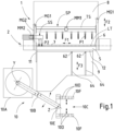
- number 1 indicates the cutting machine for panels (P) according to the invention.
- panel P
- strip STR
- substantially flat elements for example, panels of various sizes for the construction of furniture, panels of plastic material or relative strips, etc.
- pack is to be understood as a vertically stacked set of two or more panels (P) or strips (STR).
- arrow indicates a direction and possibly also a relative way, evoking - with the term arrow - the corresponding symbol that identifies a vector (which makes it possible to verify the direction of application and the relative way).
- the cutting machine 1 is provided with an electronic control unit (numerical control or electronic system) (not shown), which is configured to control and manage the components of the cutting machine 1.
- an electronic control unit number of control or electronic system
- the cutting machine 1 is of the horizontal type with a cutting station 2 of the type with a cutting assembly (GRT) with a movable tool-holder carriage, which can slide and is operated in a known manner along a guiding base 3 ( figure 2 ) according to directions and ways defined by an arrow (F1) ( figure 1 ).
- GRT cutting assembly
- F1 figure 1
- the tool or tools (a cutting blade 4, mounted on the cutting assembly (GRT), is visible in figure 2 , whereas a possible scorer is not shown) are lifted (or lowered in a different machine type) above a base work plane 5 ( figures 1 and 2 ) along the guiding base 3, while they are lowered (or lifted in a different machine type) during the step of returning to the start-of-cut position.
- a known upper pressing member 7 is configured, during the cutting step, to lock the panels (P) on the base work plane 5 by means of a known vertical movement.
- the upper pressing device 7 During the positioning of the panels (P), before the cut, the upper pressing device 7 always is in a lifted position.
- the cutting machine 1 is provided with a main pushing device (SP), in the form of an overhead crane, provided with a first plurality of grippers (P1) and possibly with a secondary pushing device (SS) equipped with a second plurality of grippers (P2) ( figure 1 ).
- SP main pushing device
- P1 first plurality of grippers
- SS secondary pushing device
- P2 second plurality of grippers
- the cutting machine 1 for panels (P) normally comprises a feeding plane 8 located upstream of the cutting station 2 ( figures 1 , 2 ).
- Said feeding plane 8 can be, for example, of the roller type and can be provided with optional rotation means (not shown) for rotating the panels (P) and/or portions thereof in order to obtain the orientation needed to carry out the various cuts to size entailed in the cutting scheme to be performed.
- the work area (AL) ( figure 1 ) of the cutting machine 1 then comprises, in sequence, the aforementioned feeding plane 8, the base work plane 5 and continues past the base work plane 5 in the form of one or more support planes 9.
- the support plane (or planes) 9 downstream of the cutting station 2 is located, preferably but not necessarily, at the same level as the other two planes 5 and 8 and is intended to support the panels (P), the strips (STR) and any other cut portions to allow for their correct orientation and possible reinsertion in the cutting machine 1 by a robotic manipulator 10 also in charge of unloading the cut panels ( figures 1 , 3 , 4, 5 , 6 , 7 , 8 ) (see below).
- the main pushing device (SP) and the secondary pushing device (SS), when present, by means of the relative grippers (P1), (P2), are configured to pick up the various elements to be cut (panels (P), strips (STR), etc.) from the feeding plane 8 (or from the support plane 9) and to position them, according to the set program, on the cutting line (LT) where the cutting of said elements takes place by means of the cutting station 2 and, in particular, by means of the blade 4.
- the operating field of the main pushing device (SP) extends above the feeding plane 8, which, therefore, has a width almost coinciding with that of the cutting line (LT) and a length almost coinciding with the usable stroke of the main pushing device (SP) determined by the rear limit stop in its retracted position (not shown) and by the cutting line (LT) in its advanced position.
- the rear limit stop of the main pushing device (SP) can be extended to allow the panels (P) to be automatically loaded from an area behind the feeding plane 8 and the front limit stop can be extended beyond the cutting line (LT) and up to and/or near the support plane 9.
- the secondary pushing device (SS) ( figure 1 ) has a usable stroke almost identical to that of the main pushing device (SP) and has at least one end that is forced to slide along respective second guiding means (MG2) parallel to the first guiding means (MG1) of the main pushing device (SP).
- the main pushing device (SP) is operated, along the first guiding means (MG1), by first longitudinal moving means (MM1) of the known type ( figure 1 ), whereas the secondary pushing device (SS) is operated along the second guiding means (MG2) by second longitudinal movement means (MM2) of the known type ( figure 1 ).
- the secondary pushing device (SS) and the main pushing device (SP) are located at different heights with respect to the feeding plane 8 in order to avoid mutual interference and permit the respective independent movements along the same feeding plane 8.
- the main pushing device (SP) and the secondary pushing device (SS) share the same feeding plane 8 and the same cutting station 2.
- the pushing devices (SP) and (SS) can move horizontally according to the direction and the ways identified by an arrow (F2) ( figure 1 ) substantially perpendicular to the cutting line (LT) and, hence, to the aforementioned arrow (F1) according to a direction substantially parallel to the feeding direction of the panels in the cutting machine (1).
- the secondary pushing device (SS) can possibly move laterally according to the direction and the ways (F1) in order to position its grippers (P2) depending on the width of the strips (STR) to be picked up and cut.
- a reference square 11 is provided so that the strips (STR) or the panels (P) can stroke against it in order to be perfectly cut transversely at 90 degrees.
- the cutting machine 1 is configured to execute both longitudinal cuts on original panels (P) and transverse (cross) cuts on the produced strips (STR) to obtain the cut-to-size panels (P) as desired.
- third or fourth rotation cuts are further cuts, generally named third or fourth rotation cuts, on panels already obtained from a previous cross cut operation. Panels (P) that, hence, should be again rotated and inserted into the cutting station 2 and in particular against the reference square 11 and into the grippers (P1 and or P2) of the main pusher (SP) and/or of the secondary pusher (SS).
- a trapdoor 12 for unloading the trimming residues is located between the base work plane 5 and the support plane 9.
- the trapdoor 12 ( figure 2 ) is therefore located downstream of the cutting station 2 with respect to the normal flow of the panels (P) (and/or of the strips (STR)).
- This trapdoor 12 is used to automatically unload, in a known manner and under the work area (AL), the swarf (trimming residues) that is generated in the area of the cutting station 2.
- a container 13 for collecting swarf (trimming residues) is located under the unloading trapdoor 12.
- a conveyor belt (not shown) can be provided for the automatic removal of swarf.
- the cutting machine 1 is provided with the robotic manipulator 10 for locking and transferring the panels (P), said robotic manipulator 10 being shown in the attached figures in a non-limiting position downstream of the feeding plane 8 and of the cutting station 2.
- the robotic manipulator 10 is located externally and next to the support plane 9 downstream of the cutting station 2 and beside the reference square 11.
- the robotic manipulator 10 is controlled by the electronic control unit of the cutting machine 1, but it could also be controlled by an electronic control unit of its own (not shown), which is configured to communicate (exchange data) with the electronic control unit of the cutting machine 1.
- the electronic control unit independently or together with other control units, is configured to operatively manage all the parts of the cutting machine 1 and, hence, all its operational phases, directly or indirectly including those of the robotic manipulator 10.
- the electronic control unit is also configured to manage and store, instant by instant, all the phases relating to the panels being processed on the work area (AL) and, therefore, the dimensions of each single panel (P) or pack of panels (P), their exact position on the work area (AL) and, hence, also the phase or phases to which each single panel (P) or pack of panels (P) must be subjected in the relative cutting and/or unloading cycle are known instant by instant.
- the robotic manipulator 10 is configured and designed to feed the cut strips (STR) and/or the cut panels (P) again to the main pushing device (SP) and/or to the secondary pushing device (SS) for the execution of the transverse cuts and/or of the further third or fourth phase cuts as previously said. Obviously, this means that previously obtained strips (STR) and/or panels (P) must be rotated and correctly fed to the cutting station 2.
- the robotic manipulator 10 is configured and designed to unload the already finished cut panels (P) onto dedicated pallets (PPL) (evacuation means) (figure 10) and/or onto roller tracks (not shown) for their manual and/or automatic removal.
- the robotic manipulator 10 ( figures 1 , 3 , 4, 5 , 6 , 7 , 8 ) comprises a base 10A, a system of articulated arms 10B connected to one another and to the base 10A and a pick-up unit 10C fixed to the articulated arms 10B.
- the robotic manipulator 10 could consist of a manipulator member with Cartesian axes movements.
- the robotic manipulator 10 which acts as a pick-up unit, can rotate around a relative axis (Y) ( figures 1 , 4 ).
- the pick-up unit 10C of the robotic manipulator 10 comprises a plurality of suction cups 10D, which, in a known manner, are configured and designed to adhere to an upper surface of at least one panel (P) or of a strip (STR); said panel (P) or strips (STR) possibly being part of a pack of panels (P) or of a pack of strips (STR), respectively.
- the panels (P) (or the strips (STR)) to be moved by the robotic manipulator 10 are gripped by means of the suction cups 10D.
- the pick-up unit 10C ( figure 1 ) comprises a cross member 10E hinged, in a known manner, to the articulated arms 10B in the area of an axis (Z) and two arms 10F on which the aforementioned suction cups 10D are mounted.
- These arms 10F by means of known means, can be moved towards/away from one another, sliding on the cross member 10E, in order to adjust the pick-up system according to the dimensions of the strips (STR) or of the panels (P) to be handled.
- the arms 10F of the robotic manipulator are provided with poles that are vertically movable according to the direction and the ways (F4) and are configured to lock and push the panels (P) or the packs of panels (P) and/or the strips (STR) or the packs of strips (STR) and to transfer them by having them slide on the work area (AL) and, in particular, on the support plane 9 against the reference square 11.
- one of the objects of the invention is to provide a cutting machine 1 with a simple and inexpensive equipment configured to complement the action of the robotic manipulator 10, which is only left with the most complicated operations typical of a robotic system.
- This apparatus 60 comprises a carriage 61 provided with two poles 62 (retractable lifting elements), which, in the rest position, are recessed and under the support plane 9.
- the carriage 61 driven by its own and known means, can translate on a linear guide 63 according to a direction and ways identified by an arrow (F3) ( figure 2 ) perpendicular to the cutting line (LT) and substantially parallel to the arrow (F2).
- the two poles 62 can slide in respective grooves 64 made on the support plane 9 ( figure 1 ). Since the grooves 64 are parallel to the linear guide 63, the two poles 62 can only translate according to the aforementioned arrow (F3).
- the two poles 62 can translate vertically according to a direction and ways identified by an arrow (F4).
- the arrow (F4) is perpendicular to the surface of the support plane 9 ( figure 2 ).
- the two poles 62 can disappear under the support plane 9, thus allowing the panels (P) (or the strips (STR)) to freely move on the support plane 9, or they can be lifted (according to the arrow (F4)) above the support plane 9 in order to be able to push one or more strips (STR) at a time, even in a pack, according to a direction and ways indicated by the arrow (F3) orthogonal to the cutting station 2. Both situations are shown in figure 2 .
- One of the advantages of using the apparatus 60 lies in that, during the step of unloading the panels (P) onto the pallet (PPL) ( figure 3 , 5 , 6 , 7 , 8 ) carried out through the use of the robotic manipulator 10, the step of moving the strips (STR) away from the cutting station 2 ( figure 2 ) and of spacing of the strips (STR) apart from one another ( figures 7 , 8 ), according to a program set in the electronic control unit, can be carried out by the apparatus 60.
- the apparatus 60 works substantially simultaneously, basically in masked time, with respect to the action of the robotic manipulator 10.
- the robotic manipulator 10 can only concentrate on the 90-degree rotation of the strips (STR) for the execution of the relative transverse cuts (and/or on the rotation of the cut panels (P) that require further third or fourth rotation cuts) and on the unloading of the cut panels (P) onto pallets (PPL) ( figures 7 and 8 ), with a consequent saving of the total cutting times needed for panels (P).
- the electronic control unit is configured for the control and management of the apparatus (60) and of the robotic manipulator (10) and to control and manage all their relative simultaneous separation, positioning, transfer and unloading operation.
- the electronic control unit is configured for the control and management of the apparatus (60) and for the correct separation and for the precise positioning of the panels (P) and/or groups of panels (P) coming out of the cutting station (2) according to a program set in the electronic control unit.
- the main pushing device (SP) pushes the strip (STR) (or the strips (STR)) to be separated on the support plane 9 by means of the remaining portion of the panel (P) until said strip (STR) (or strips (STR)) is positioned just beyond the two poles 62 in their rest position in the vicinity of the unloading trapdoor 12. Then the main pushing device (SP), by means of the relative grippers (P1), retracts the remaining portion of the panel (P), thus causing it to detach itself from the strip (STR) (or the strips) pushed on the support plane 9.
- This second strip or pack of strips (STR) (or group of strips or packs of strips (STR)) in the parking zone on the support plane 9 takes place by taking into account the presence or the absence of the previous strip (STR) and, in case, by making sure to leave the necessary space between them.
- This operation aimed at obtaining said separation and precise positioning of the strip or strips (STR) on the support plane 9 is determined by the need to have a transverse cutting evenness in the various groups of strips (STR) placed in the parking zone; in practice, the strips or packs of strips (STR) with the same transverse cutting cycle will be grouped together.
- the separation is also necessary in order to facilitate the picking up of the single strips (STR) or groups of strips (STR) by the robotic manipulator 10 configured to transfer them in the transverse cutting zone and against the reference square 11 by means of the pick-up unit 10C or other dedicated means.
- Figure 3 shows, in plan view, two packs of strips (STR1) moved and positioned on the support plane 9 in a well-defined position by means of the two poles 62 of the apparatus 60. All this permits the continuation, without any interruption, of the unloading cycle of the previous cut and finished panels (P).
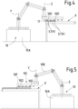
- the robotic manipulator 10 proceeds to transfer the strips (STR1), possibly with several cycles, to the transverse zone and against the reference square 11 ( figure 4 ) so that the relative transverse cutting operation is carried out by means of the main pushing device (SP) or possibly by means of the secondary pushing device (SS).
- SP main pushing device
- SS secondary pushing device
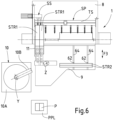
- Figure 6 shows the simultaneous operations for the transfer of the two strips (STR2) to the area of their relative parking on the support plane 9 and for the unloading of the panels (P) (see the detail of figure 5 ) cut transversely and obtained from the strips (STR1) previously rotated and transferred by the robotic manipulator 10.
- SP two pushing devices
- SS two pushing devices
- Figure 7 shows how the pack of strips (STR3) was properly positioned and spaced apart from the packs of strips (STR2) previously positioned on the support plane 9 during the continuation of the unloading of the panels obtained from the previous strips (STR1) by the robotic manipulator 10 onto the pallets (PPL).
- Figure 8 shows the subsequent processing sequence, wherein the main pushing device (SP), thanks to the use of the apparatus 60, was able to end the cutting operations by completing the cutting of the last pack of strips (STR4) of its cutting cycle, while the robotic manipulator 10 is still dealing with the unloading, onto the pallet (PPL), of the multitude of panels (P) produced during the transverse cutting of the two previous packs of strips (STR1).
- SP main pushing device
- PPL pallet
- P the multitude of panels
- the secondary pushing device (SS) will carry out the transverse cutting of the last pack of strips (STR4) and the robotic manipulator 10 will deal with the relative unloading of the cut panels, while the main pushing device (SP), in total autonomy and together with the apparatus 60, can continue its longitudinal cutting program for the production of new strips (STR) without interrupting the action of unloading the panels (P) onto the pallet (PPL) or onto other forms of evacuation carried out by the robotic manipulator 10.
- one of the two actions should be interrupted in order to continue only one of the two.
- SP single pushing device
- the pushing device can continue with the execution of a new longitudinal cutting cycle to produce new panels and/or new strips (STR) from a new panel (P) without interruptions, while the robotic manipulator 10 performs the unloading of the previously produced panels (P).
Landscapes
- Engineering & Computer Science (AREA)
- Mechanical Engineering (AREA)
- Life Sciences & Earth Sciences (AREA)
- Wood Science & Technology (AREA)
- Forests & Forestry (AREA)
- Specific Conveyance Elements (AREA)
Applications Claiming Priority (1)
| Application Number | Priority Date | Filing Date | Title |
|---|---|---|---|
| IT102023000023604A IT202300023604A1 (it) | 2023-11-09 | 2023-11-09 | Macchina sezionatrice |
Publications (2)
| Publication Number | Publication Date |
|---|---|
| EP4552779A1 true EP4552779A1 (fr) | 2025-05-14 |
| EP4552779B1 EP4552779B1 (fr) | 2026-03-25 |
Family
ID=89897248
Family Applications (1)
| Application Number | Title | Priority Date | Filing Date |
|---|---|---|---|
| EP24211304.1A Active EP4552779B1 (fr) | 2023-11-09 | 2024-11-07 | Machine à découper |
Country Status (2)
| Country | Link |
|---|---|
| EP (1) | EP4552779B1 (fr) |
| IT (1) | IT202300023604A1 (fr) |
Citations (5)
| Publication number | Priority date | Publication date | Assignee | Title |
|---|---|---|---|---|
| IT202000028304A1 (it) * | 2020-11-25 | 2022-05-25 | Scm Group Spa | Sistema per la variazione della superficie della stazione di scarico di una macchina per la lavorazione di pezzi e metodo di funzionamento del sistema stesso. |
| EP4008508A1 (fr) * | 2020-12-03 | 2022-06-08 | IMA Schelling Austria GmbH | Procédé de sciage d'au moins une plaque |
| US20220193802A1 (en) * | 2020-12-03 | 2022-06-23 | Ima Schelling Austria Gmbh | Panel cutting machine for cutting work pieces |
| EP3647004B1 (fr) | 2018-11-05 | 2022-09-07 | BIESSE S.p.A. | Machine de découpage pour découper des panneaux en bois ou analogue |
| IT202100027578A1 (it) * | 2021-10-27 | 2023-04-27 | Tic Tac Srl | Processo ed impianto per la lavorazione di pannelli stampabili |
-
2023
- 2023-11-09 IT IT102023000023604A patent/IT202300023604A1/it unknown
-
2024
- 2024-11-07 EP EP24211304.1A patent/EP4552779B1/fr active Active
Patent Citations (5)
| Publication number | Priority date | Publication date | Assignee | Title |
|---|---|---|---|---|
| EP3647004B1 (fr) | 2018-11-05 | 2022-09-07 | BIESSE S.p.A. | Machine de découpage pour découper des panneaux en bois ou analogue |
| IT202000028304A1 (it) * | 2020-11-25 | 2022-05-25 | Scm Group Spa | Sistema per la variazione della superficie della stazione di scarico di una macchina per la lavorazione di pezzi e metodo di funzionamento del sistema stesso. |
| EP4008508A1 (fr) * | 2020-12-03 | 2022-06-08 | IMA Schelling Austria GmbH | Procédé de sciage d'au moins une plaque |
| US20220193802A1 (en) * | 2020-12-03 | 2022-06-23 | Ima Schelling Austria Gmbh | Panel cutting machine for cutting work pieces |
| IT202100027578A1 (it) * | 2021-10-27 | 2023-04-27 | Tic Tac Srl | Processo ed impianto per la lavorazione di pannelli stampabili |
Also Published As
| Publication number | Publication date |
|---|---|
| IT202300023604A1 (it) | 2025-05-09 |
| EP4552779B1 (fr) | 2026-03-25 |
Similar Documents
| Publication | Publication Date | Title |
|---|---|---|
| CN114274266B (zh) | 用于分割板状工件的板分割设备以及方法 | |
| EP2823932B1 (fr) | Procédé d'ébauchage de panneau de véhicule motorisé | |
| US4541762A (en) | Apparatus for loading and/or unloading machine tools or the like | |
| CN107206614B (zh) | 用于分割板状工件的板材分割设备及其运行方法 | |
| US12383969B2 (en) | Panel cutting machine for cutting work pieces | |
| US10518437B2 (en) | Wood door slab processing system, and related methods | |
| EP4552776A1 (fr) | Machine à découper et procédé de fonctionnement associé | |
| CN115610895B (zh) | 一种货物柔性补货方法、装置 | |
| US6606531B1 (en) | Sheet material loader/unloader for machine tools | |
| EP4552779B1 (fr) | Machine à découper | |
| US20050092157A1 (en) | Panel turning device | |
| WO2003097495A1 (fr) | Procede et processus de chargement et dechargement de pieces | |
| JP2004136300A (ja) | プレスライン | |
| EP0498345A2 (fr) | Méthode et dispositif pour la fabrication de produits de feuilles métalliques | |
| JPH0473612B2 (fr) | ||
| US11701793B2 (en) | Method for processing panel-shaped workpieces | |
| EP4556147B1 (fr) | Machine à découper et procédé de fonctionnement associé | |
| JPH0429498B2 (fr) | ||
| EP4552777A1 (fr) | Machine à découper et procédé de fonctionnement associé | |
| EP4552778A1 (fr) | Machine à découper et procédé de fonctionnement associé | |
| CN223751647U (zh) | 自动化系统 | |
| CN106392190A (zh) | 用于加工工件,特别是锯片的设备 | |
| CN220739631U (zh) | 门框自动切角生产线 | |
| CN111687959A (zh) | 木料多规格同时定尺锯切和接长的设备及其加工方法 | |
| JP2003170231A (ja) | 板材加工機 |
Legal Events
| Date | Code | Title | Description |
|---|---|---|---|
| PUAI | Public reference made under article 153(3) epc to a published international application that has entered the european phase |
Free format text: ORIGINAL CODE: 0009012 |
|
| STAA | Information on the status of an ep patent application or granted ep patent |
Free format text: STATUS: THE APPLICATION HAS BEEN PUBLISHED |
|
| AK | Designated contracting states |
Kind code of ref document: A1 Designated state(s): AL AT BE BG CH CY CZ DE DK EE ES FI FR GB GR HR HU IE IS IT LI LT LU LV MC ME MK MT NL NO PL PT RO RS SE SI SK SM TR |
|
| STAA | Information on the status of an ep patent application or granted ep patent |
Free format text: STATUS: REQUEST FOR EXAMINATION WAS MADE |
|
| 17P | Request for examination filed |
Effective date: 20250707 |
|
| REG | Reference to a national code |
Ref country code: DE Ref legal event code: R079 Free format text: PREVIOUS MAIN CLASS: B23D0047040000 Ipc: B27B0031080000 Ref country code: DE Ref legal event code: R079 Ref document number: 602024003446 Country of ref document: DE Free format text: PREVIOUS MAIN CLASS: B23D0047040000 Ipc: B27B0031080000 |
|
| GRAP | Despatch of communication of intention to grant a patent |
Free format text: ORIGINAL CODE: EPIDOSNIGR1 |
|
| STAA | Information on the status of an ep patent application or granted ep patent |
Free format text: STATUS: GRANT OF PATENT IS INTENDED |
|
| RIC1 | Information provided on ipc code assigned before grant |
Ipc: B27B 31/08 20060101AFI20251008BHEP Ipc: B23D 47/04 20060101ALI20251008BHEP Ipc: B27B 5/065 20060101ALI20251008BHEP |
|
| INTG | Intention to grant announced |
Effective date: 20251023 |
|
| GRAS | Grant fee paid |
Free format text: ORIGINAL CODE: EPIDOSNIGR3 |
|
| GRAA | (expected) grant |
Free format text: ORIGINAL CODE: 0009210 |
|
| STAA | Information on the status of an ep patent application or granted ep patent |
Free format text: STATUS: THE PATENT HAS BEEN GRANTED |
|
| AK | Designated contracting states |
Kind code of ref document: B1 Designated state(s): AL AT BE BG CH CY CZ DE DK EE ES FI FR GB GR HR HU IE IS IT LI LT LU LV MC ME MK MT NL NO PL PT RO RS SE SI SK SM TR |
|
| REG | Reference to a national code |
Ref country code: CH Ref legal event code: F10 Free format text: ST27 STATUS EVENT CODE: U-0-0-F10-F00 (AS PROVIDED BY THE NATIONAL OFFICE) Effective date: 20260325 Ref country code: GB Ref legal event code: FG4D |
|
| REG | Reference to a national code |
Ref country code: DE Ref legal event code: R096 Ref document number: 602024003446 Country of ref document: DE |
|
| REG | Reference to a national code |
Ref country code: IE Ref legal event code: FG4D |