EP4552893A2 - Procédés et dispositifs d'incrustation de données - Google Patents
Procédés et dispositifs d'incrustation de données Download PDFInfo
- Publication number
- EP4552893A2 EP4552893A2 EP25159190.5A EP25159190A EP4552893A2 EP 4552893 A2 EP4552893 A2 EP 4552893A2 EP 25159190 A EP25159190 A EP 25159190A EP 4552893 A2 EP4552893 A2 EP 4552893A2
- Authority
- EP
- European Patent Office
- Prior art keywords
- holographic
- holographic element
- image
- wavelengths
- ground glass
- Prior art date
- Legal status (The legal status is an assumption and is not a legal conclusion. Google has not performed a legal analysis and makes no representation as to the accuracy of the status listed.)
- Pending
Links
Images




Classifications
-
- G—PHYSICS
- G02—OPTICS
- G02B—OPTICAL ELEMENTS, SYSTEMS OR APPARATUS
- G02B27/00—Optical systems or apparatus not provided for by any of the groups G02B1/00 - G02B26/00, G02B30/00
- G02B27/01—Head-up displays
- G02B27/0101—Head-up displays characterised by optical features
- G02B27/0103—Head-up displays characterised by optical features comprising holographic elements
-
- B—PERFORMING OPERATIONS; TRANSPORTING
- B60—VEHICLES IN GENERAL
- B60K—ARRANGEMENT OR MOUNTING OF PROPULSION UNITS OR OF TRANSMISSIONS IN VEHICLES; ARRANGEMENT OR MOUNTING OF PLURAL DIVERSE PRIME-MOVERS IN VEHICLES; AUXILIARY DRIVES FOR VEHICLES; INSTRUMENTATION OR DASHBOARDS FOR VEHICLES; ARRANGEMENTS IN CONNECTION WITH COOLING, AIR INTAKE, GAS EXHAUST OR FUEL SUPPLY OF PROPULSION UNITS IN VEHICLES
- B60K35/00—Instruments specially adapted for vehicles; Arrangement of instruments in or on vehicles
-
- B—PERFORMING OPERATIONS; TRANSPORTING
- B60—VEHICLES IN GENERAL
- B60K—ARRANGEMENT OR MOUNTING OF PROPULSION UNITS OR OF TRANSMISSIONS IN VEHICLES; ARRANGEMENT OR MOUNTING OF PLURAL DIVERSE PRIME-MOVERS IN VEHICLES; AUXILIARY DRIVES FOR VEHICLES; INSTRUMENTATION OR DASHBOARDS FOR VEHICLES; ARRANGEMENTS IN CONNECTION WITH COOLING, AIR INTAKE, GAS EXHAUST OR FUEL SUPPLY OF PROPULSION UNITS IN VEHICLES
- B60K35/00—Instruments specially adapted for vehicles; Arrangement of instruments in or on vehicles
- B60K35/20—Output arrangements, i.e. from vehicle to user, associated with vehicle functions or specially adapted therefor
- B60K35/21—Output arrangements, i.e. from vehicle to user, associated with vehicle functions or specially adapted therefor using visual output, e.g. blinking lights or matrix displays
- B60K35/211—Output arrangements, i.e. from vehicle to user, associated with vehicle functions or specially adapted therefor using visual output, e.g. blinking lights or matrix displays producing three-dimensional [3D] effects, e.g. stereoscopic images
-
- B—PERFORMING OPERATIONS; TRANSPORTING
- B60—VEHICLES IN GENERAL
- B60K—ARRANGEMENT OR MOUNTING OF PROPULSION UNITS OR OF TRANSMISSIONS IN VEHICLES; ARRANGEMENT OR MOUNTING OF PLURAL DIVERSE PRIME-MOVERS IN VEHICLES; AUXILIARY DRIVES FOR VEHICLES; INSTRUMENTATION OR DASHBOARDS FOR VEHICLES; ARRANGEMENTS IN CONNECTION WITH COOLING, AIR INTAKE, GAS EXHAUST OR FUEL SUPPLY OF PROPULSION UNITS IN VEHICLES
- B60K35/00—Instruments specially adapted for vehicles; Arrangement of instruments in or on vehicles
- B60K35/20—Output arrangements, i.e. from vehicle to user, associated with vehicle functions or specially adapted therefor
- B60K35/29—Instruments characterised by the way in which information is handled, e.g. showing information on plural displays or prioritising information according to driving conditions
-
- B—PERFORMING OPERATIONS; TRANSPORTING
- B60—VEHICLES IN GENERAL
- B60K—ARRANGEMENT OR MOUNTING OF PROPULSION UNITS OR OF TRANSMISSIONS IN VEHICLES; ARRANGEMENT OR MOUNTING OF PLURAL DIVERSE PRIME-MOVERS IN VEHICLES; AUXILIARY DRIVES FOR VEHICLES; INSTRUMENTATION OR DASHBOARDS FOR VEHICLES; ARRANGEMENTS IN CONNECTION WITH COOLING, AIR INTAKE, GAS EXHAUST OR FUEL SUPPLY OF PROPULSION UNITS IN VEHICLES
- B60K2360/00—Indexing scheme associated with groups B60K35/00 or B60K37/00 relating to details of instruments or dashboards
- B60K2360/18—Information management
- B60K2360/188—Displaying information using colour changes
-
- B—PERFORMING OPERATIONS; TRANSPORTING
- B60—VEHICLES IN GENERAL
- B60K—ARRANGEMENT OR MOUNTING OF PROPULSION UNITS OR OF TRANSMISSIONS IN VEHICLES; ARRANGEMENT OR MOUNTING OF PLURAL DIVERSE PRIME-MOVERS IN VEHICLES; AUXILIARY DRIVES FOR VEHICLES; INSTRUMENTATION OR DASHBOARDS FOR VEHICLES; ARRANGEMENTS IN CONNECTION WITH COOLING, AIR INTAKE, GAS EXHAUST OR FUEL SUPPLY OF PROPULSION UNITS IN VEHICLES
- B60K2360/00—Indexing scheme associated with groups B60K35/00 or B60K37/00 relating to details of instruments or dashboards
- B60K2360/20—Optical features of instruments
- B60K2360/33—Illumination features
- B60K2360/333—Lasers
-
- B—PERFORMING OPERATIONS; TRANSPORTING
- B60—VEHICLES IN GENERAL
- B60K—ARRANGEMENT OR MOUNTING OF PROPULSION UNITS OR OF TRANSMISSIONS IN VEHICLES; ARRANGEMENT OR MOUNTING OF PLURAL DIVERSE PRIME-MOVERS IN VEHICLES; AUXILIARY DRIVES FOR VEHICLES; INSTRUMENTATION OR DASHBOARDS FOR VEHICLES; ARRANGEMENTS IN CONNECTION WITH COOLING, AIR INTAKE, GAS EXHAUST OR FUEL SUPPLY OF PROPULSION UNITS IN VEHICLES
- B60K2360/00—Indexing scheme associated with groups B60K35/00 or B60K37/00 relating to details of instruments or dashboards
- B60K2360/20—Optical features of instruments
- B60K2360/33—Illumination features
- B60K2360/334—Projection means
-
- G—PHYSICS
- G02—OPTICS
- G02B—OPTICAL ELEMENTS, SYSTEMS OR APPARATUS
- G02B27/00—Optical systems or apparatus not provided for by any of the groups G02B1/00 - G02B26/00, G02B30/00
- G02B27/01—Head-up displays
- G02B27/0101—Head-up displays characterised by optical features
- G02B27/0103—Head-up displays characterised by optical features comprising holographic elements
- G02B2027/0109—Head-up displays characterised by optical features comprising holographic elements comprising details concerning the making of holograms
Definitions
- This application relates to methods and devices for data projection, particularly for so-called head-up displays (HUDs).
- HUDs head-up displays
- this application relates to such methods and devices that can be used in vehicles, especially motor vehicles.
- the methods and devices described in this application can also be used in other applications, particularly for all transparent panes.
- the described methods and devices can also be used for transparent panes on other vehicles, such as trains, buses, ships, or aircraft, or even in the real estate sector for window panes where data projection is desired.
- mirrored data can include, for example, images, videos, symbols, characters, and/or numbers.
- One area of application for such methods and devices for data projection is in the automotive sector, for example, to provide data to a vehicle operator, such as a car driver, while driving. This can be achieved, for example, by appropriate elements in a vehicle's windshield, allowing the driver to view the data without having to specifically focus on a display, such as an instrument cluster, to receive data. Instead, they can essentially perceive this data without significantly shifting their gaze away from the road.
- data mirroring which can also be used for automotive applications, are from the WO 2014/115095 A2 It uses a holographic screen, and depending on the distance of this screen from the human eye, a special contact lens is required to easily focus on this screen.
- a device according to claim 1 is provided.
- the subclaims define further embodiments.
- the device may be configured to display a three-dimensional object.
- the imaging device may comprise an amplitude modulator and a phase modulator for generating three-dimensional images.
- the holographic element may be configured to image an image provided by the imaging device onto at least one intermediate image viewable from the viewing location.
- the distance between the intermediate image and the viewing location can be at least 2 m, but is not limited to this.
- the at least one intermediate image can comprise a real image. This allows, for example, 2D or 3D images (or objects) to be displayed in a plane between the holographic element (or a display) and a viewer.
- the at least one intermediate image may comprise a virtual image.
- the at least one intermediate image can include at least two intermediate images. This allows for representation at different levels, in different locations, or for different viewers.
- the at least two intermediate images can in particular be arranged at different distances from the holographic element, which corresponds to a representation in different planes.
- the at least two intermediate images can also be viewed from different viewing locations. For example, different content can be provided to different viewers (e.g., driver and passenger), or an available eyebox can be enlarged.
- the holographic element can be configured to generate a first intermediate image of the at least two intermediate images based on a first group of wavelengths and a second intermediate image of the at least two intermediate images based on a second group of wavelengths that differ from the wavelengths of the first group. Separate color images can thus be generated.
- the imaging device can comprise a first imager for generating a first intermediate image of the at least two intermediate images and a second imager (121) for generating a second intermediate image of the at least two intermediate images, wherein the first imager and the second imager are arranged at different locations.
- a first imager for generating a first intermediate image of the at least two intermediate images
- a second imager (121) for generating a second intermediate image of the at least two intermediate images
- the holographic element can also comprise a holographic ground glass.
- the hologram plane acts like a projection screen for a defined wavelength and deflection angle range. This particularly facilitates the use of compact laser projectors.
- the image is created directly as a real image on the screen.
- the device may further comprise the support, wherein the support may comprise a windshield arranged at an angle ⁇ 30°, for example ⁇ 15° or equal to 15°, to the vertical.
- the holographic element By adapting the holographic element to an approximately vertical support (for example in the range of less than 30° to the vertical), it can be easily used in trucks, buses and other vehicles with approximately vertical windscreens.
- An angle between a main ray of light coming from the imaging device towards the holographic element and a perpendicular on the windshield can be between 40 and 80°.
- the holographic element may be configured to direct light incident on the holographic element at a specific angular range to the viewing location and to be transparent to light outside the specific angular range.
- Such a narrowband allows for high transparency for most visible light, especially despite the provision of the holographic element.
- the ambient impression is not noticeably impaired.
- the one or more wavelength ranges may include a wavelength in the red range, a wavelength in the green range, and a wavelength in the blue range. It is preferred that the wavelengths of this imaging device are precisely matched to the wavelengths of the holographic element, for example, with a deviation of less than 2 nm, which allows pixels of different colors to be precisely aligned laterally and in depth. lie on top of each other, allowing mixed colors, such as white, to be produced relatively precisely. For monochromatic use, larger deviations or a wider operating range (e.g., in the range of 30 nm) are possible. More than three such wavelengths can also be used, for example, to enable polychromatic operation.
- the one or more wavelength ranges may comprise a first group of wavelength ranges and a second group of wavelength ranges, wherein the holographic element may be configured to direct wavelengths of the first group to a different viewing location than wavelengths of the second group. This allows for the display of color images at different locations.
- the combination of operating wavelengths and a main deflection direction can be specifically designed such that the reflection hologram in or on the windshield blocks light from the surroundings, particularly from the driver's primary viewing directions.
- the blocked wavelengths can correspond to those of commercial laser pointers.
- the specially designed HUD is also capable of effectively reducing the risk of accidental or intentional dazzling or injury to the driver caused by non-eye-safe laser sources.
- the holographic element may be configured to protect a viewer of the holographic element from external laser radiation.
- the holographic element can have an imaging function.
- the holographic element can be adapted to a curvature of the carrier, e.g. a windshield, e.g. by appropriate exposure.
- the illuminating may include illuminating with light of a red wavelength, a green wavelength, and a blue wavelength.
- a use of a holographic element in a windshield for protection against laser pointers is provided.
- a holographic element is used for data reflection.
- the holographic element can, in particular, be wavelength-selective, for example, for a red, a green, and/or a blue wavelength, and be transparent to other wavelengths.
- a device according to an embodiment is shown.
- the carrier 10 can in particular be a windshield of a vehicle.
- the carrier 10 is an approximately vertical windshield, for example a windshield inclined by a maximum of 15° or a maximum of 10° to the vertical, as is used, for example, in buses or trucks.
- Such windshields can in particular have curvatures.
- the holographic element 11 is provided on or in the carrier 10.
- the holographic element 11 can, for example, act as a ground glass, but can also act as an imaging device to produce an intermediate image. Examples of this will be described later with reference to the Fig. 2 and 3 explained.
- the holographic element 11 can be narrowband wavelength-selective, i.e., it can have an imaging function and/or ground glass function only for wavelengths within one or more narrow spectral ranges, while remaining transparent for the remaining wavelengths. In this way, the holographic element 11 is transparent for most wavelengths, allowing, for example, a view through a windshield serving as a carrier 10.
- Narrowband can mean that the holographic element functions only in one or more spectral ranges with a width of ⁇ 20 nm or ⁇ 10 nm, in particular for specific wavelengths ⁇ a manufacturing-related tolerance.
- a holographic function can be present for a red, a blue and a green wavelength, which allows the reflection of colored data while remaining transparent for most of the visible light.
- the device of Fig. 1 further comprises an imaging device 12 (hereinafter also referred to as imager), which directs light corresponding to data to be reflected towards the holographic element 11.
- the imaging device 12 can, for example, scan the holographic element 11 with one or more laser beams (for example, a red, a green and/or a blue laser beam).
- the imaging device 12 can, for example, itself contain a ground glass, and the light corresponding to the light on the ground glass is directed as light 13 towards the holographic element 11.
- the imaging device 12 can also comprise, for example, a display such as an (O)LED, LCD or TFT display as the imaging element.
- the holographic element 11 then directs the light 13 according to a holographic function of the holographic element 11 as light 14 to an eye 15 of a viewer, whereby the viewer can view the reflected data.
- data is to be understood broadly and can refer to any symbols, letters, numbers, images, videos and/or combinations thereof.
- the installation space required for data projection can be reduced.
- the imaging properties of the hologram 11 can be selected such that additional imaging elements, for example for magnification, such as freeform mirrors or lenses, and/or elements for beam folding are not necessary.
- the Fig. 2 shows a device for data input according to an embodiment.
- the embodiment of the Fig. 2 serves to project data into a windshield 20, which serves as a carrier for a holographic element 25.
- the windshield 20 is inclined.
- the windshield 20 may be vertical or approximately vertical, as is the case, for example, with the windshield of a truck or a bus.
- a holographic element 25 is arranged on or in the windshield 20.
- the holographic element 25 can, in particular, comprise a volume hologram in which an imaging function has been holographed in one or more layers.
- this function can, in particular, be holographed for three discrete wavelengths in the red, blue, and green ranges, so that the holographic element 25 has an imaging function for these three wavelengths, as described below, while being transparent for other wavelengths, thus enabling viewing through the windshield.
- An imaging device 21 illuminates the holographic element 25, as indicated by a beam 22, with an image to be displayed corresponding to the data to be reflected.
- the image to be displayed can be generated, for example, by scanning a ground glass screen with one or more lasers or by a display device such as an LCD display, a TFT display, or a light-emitting diode (LED) display (for example, based on organic light-emitting diodes (OLED)).
- a display device such as an LCD display, a TFT display, or a light-emitting diode (LED) display (for example, based on organic light-emitting diodes (OLED)).
- the holographic element 25 is illuminated with the image at an angle to a vertical 23 on the windshield 20, wherein the angle can depend on a design of the holographic element 25.
- the holographic element 25 only displays the image for one or more specific angles of incidence (for example between the light beam 22 and the vertical 23) an imaging function, while it is transparent for other angles.
- the holographic element 25 projects the received image onto a virtual image 25.
- the virtual image 25 is displayed for an eyebox of an eye 27 of a viewer, as indicated by rays 26.
- the angle at which the virtual image 25 appears to the eye 27 differs from the angle at which the image corresponding to the beam 22 falls on the holographic element 25.
- the angles involved can be adjusted by the design of the respective holographic element 25. In particular, the angles involved can be taken into account when exposing the hologram, as can a curvature of the windshield 20.
- the function of the holographic element is effective only for one or more selected wavelengths and only for incidence at one or more angles, since, for example, a Bragg condition is only fulfilled for these angles and wavelengths.
- Light of a different color passes through the holographic element unhindered, so that the disc is transparent in this case.
- the embodiment of the Fig. 2 can therefore be easily adapted to many different windshields and can be used in particular for approximately vertical windshields.
- the virtual image 25 is projected at a distance of > 2 m, more preferably > 4 m, in particular > 6 m or > 8 m from the eye 27.
- the virtual image 25 can also be generated at a distance of ⁇ 2 m.
- an angle between the beam 22 and the vertical 23 can be in the range of 35°
- the windscreen can be at an angle of 30° to the horizontal
- a distance of the eye 27 to the windscreen can be approximately 80 cm.
- the viewing angle for the virtual image 25 can be in the range of 5°-7°, and the image 25 can be viewed at an angle of approximately 65° to the vertical on the windshield. Appropriate angles for exposing the hologram can then be selected for an exposure setup.
- FIG. 5 is a representation of a device similar to the device of Fig. 2 shown for the case of a vertical windshield.
- the windshield is designated 50, and 51 denotes a position of a corresponding holographic element.
- An imaging device 52 illuminates the holographic element 51 at an angle ⁇ between a main ray from the imaging device 52 to the holographic element 51 and a perpendicular to the windshield 50, for example, between 40 and 80°, with an image corresponding to data to be reflected.
- the holographic element 51 reproduces this image in a virtually enlarged manner, wherein the virtual image 53 can be viewed by an eye 54 within an eyebox.
- the use of the holographic element 51 offers the advantage, compared to, for example, reflective head-up displays, that it can be illuminated at essentially any angle ⁇ (for example, between 40 and 80°) and viewed close to the normal, so that the angle of incidence and angle of reflection can be different.
- the imaging device 52 can, for example, be arranged in a position above (as shown) or below the windshield. Similar configurations are also possible with holographic ground glass panels, as will be explained in more detail later.
- a holographic element 33 is provided in a windshield 30.
- the holographic element 33 has, in the embodiment of the Fig. 3 a ground glass function (also referred to as a holographic ground glass).
- This ground glass function can be implemented in particular for specific angles of incidence of incident light 32 to a perpendicular 36 and for specific wavelengths, preferably a red, a green, and/or a blue wavelength.
- the holographic element 33 can be transparent.
- the holographic element can, for example, be directly illuminated, in particular scanned, by a laser light source 31.
- the image is constructed, for example, as in conventional CRT monitors, by rapidly deflecting a luminous dot line by line.
- the luminous dot is usually formed by a laser focus, and its brightness is temporally modulated during the deflection movement in such a way that the image impression is created by temporal averaging within a time span that the human eye can no longer resolve.
- the laser light source 31 has three different lasers of red, green, and blue colors, with which the holographic element 33 can be scanned, enabling color representation.
- other types of polychromatic image generation i.e., image generation with multiple colors, are also possible.
- time-triggered display options using a micromirror array (DMD, Digital Micromirror Device) or a liquid crystal device (e.g., LCoS, Liquid Crystal on Silicon) can be used.
- DMD Digital Micromirror Device
- liquid crystal device e.g., LCoS, Liquid Crystal on Silicon
- the wavelengths used for image generation e.g., red, green, and blue wavelengths
- the deviation between the wavelengths used and the operating wavelengths of the holographic element should not exceed 2 nm. With larger deviations, it may happen that the green, red, and blue pixels of the virtual image no longer line up precisely, resulting in incorrect color mixing. With more precise coordination, however, the pixels for the different colors lie on top of each other, and essentially any color, such as white or yellow, can be created.
- a monochrome display may also be used, particularly if this is sufficient for a specific application (e.g., displaying text or numbers).
- precise wavelength matching is not required, and the holographic element can be designed for a comparatively wide operating range, for example, in the range of 30 nm.
- the light generated by the imager must then only lie within this working area in order to produce an image that is as distortion-free as possible.
- the image projected onto the holographic element 33 which acts as a ground glass screen, can then be viewed by an eye 35 at an angle to the vertical 37.
- the origin of the light for a specific pixel is determined by the interaction of the laser projector with the geometry of the screen.
- a low-distortion image can be perceived in a specific spatial area (eyebox).
- the hologram can be locally designed so that the deflection function of the laser beam can take place with adequate diffraction efficiency, i.e., the Bragg condition is observed at all locations that contribute to the image formation.
- a possible curvature of the windshield 30 is taken into account in the holographic element 33.
- a laser light source instead of a laser light source, other light sources can also be used for illumination, for example broadband sources such as a halogen lamp in combination with an imager.
- broadband sources such as a halogen lamp in combination with an imager.
- the angle of incidence and angle of reflection of the ground glass can be chosen essentially arbitrarily, so that an arrangement similar to the arrangement of the Fig. 5 adapted to vertical windshields.
- optical elements can be dispensed with, which enables a compact design, and a design is possible, for example, only with an imaging device and a holographic element in or on a windshield.
- the coordination of working wavelengths and local deflection function of a holographic element used can, in some embodiments, lead to a protective function against the light of the now widely used laser pointers in addition to the function of data reflection.
- the holographic elements already discussed are designed such that the orientation of the Bragg planes in the hologram layer, which ensure the deflection of the data beam path, enables a blocking of the penetration of light of certain wavelengths (e.g., 532 nm, 640 nm, 450 nm, 405 nm).
- the hologram structures as reflection holograms, the optical blocking effect is achieved in a similar way to a dielectric layer system by Reflection back outwards.
- the spacing of the Bragg planes must be designed such that a phase delay of the partial reflections at neighboring Bragg planes of one laser pointer wavelength occurs on the optical path of the beam in the material.
- volume hologram material with a comparatively large refractive index difference (approx. 0.03) and a comparatively thin layer thickness (approx. 10 ⁇ m), good suppression of external laser light can be achieved within a wide angular range (approx. ⁇ 10 ... 30°).
- the best laser protection for example, exists for viewing directions exactly toward the displayed image content and for the exact wavelength at which the holographic element operates.
- 60 denotes a holographic element.
- a holographic element can include a plurality of Bragg planes 65, i.e. planes of slightly different optical refractive indices, which together act as selective mirrors adapted to the pointer wavelengths.
- 61 denotes an incident beam from an imaging device, which is diffracted as beam 62 and directed to an eye of a viewer (e.g., as described with reference to Fig. 3 explained).
- 66 denotes a normal on the holographic element 60.
- a reflection function can also be achieved as protection against an externally incident laser beam 63, which is essentially reflected (diffracted) as laser beam 64.
- the holographic element 60 can be tuned to the wavelengths of laser pointers (e.g., red, green, or blue semiconductor lasers). Such wavelengths can be integrated into the design of the holographic element 60 in addition to the previously mentioned wavelengths for data reflection. This results in a combined function of data display and laser protection (functional integration) of the device without additional optically effective elements other than the holographic element (also referred to as a combiner hologram). The driver, pilot, or viewer would thus be protected by the display with respect to the main viewing directions. To adapt this protective function to different display system designs, the fact that Bragg gratings designed for a specific angle and wavelength can efficiently diffract a different wavelength at a different angle can be exploited.
- the design of the device is based on other aspects such that the main angle of incidence of the object wave from the imager to the normal vector of the Bragg planes of the grating is, for example, significantly smaller than the expected If the angle of incidence of a laser pointer is increased by, for example, more than 10°, the operating wavelength of the holographic element for displaying data must be reduced accordingly compared to that of the laser pointer (and vice versa). This would, in turn, allow the above-mentioned condition regarding the appropriate phase delay of the partial reflections at the Bragg planes for the laser pointer wavelength to be met.
- Fig. 7 is a corresponding laser protection function for the case of a holographic ground glass (according to the embodiment of the Fig. 3 ).
- 70 denotes a windshield which has a holographic ground glass 71.
- the holographic focusing screen 71 can be scanned with light from an imaging device 72, in particular a scanning laser light source with one or more wavelengths, in order to provide data to be reflected for one eye/or both eyes 73.
- the holographic ground glass in the embodiment of the Fig. 7 a protective function.
- the holographic ground glass screen 71 in the illustrated embodiment is tuned to the corresponding wavelengths as described above.
- an incident laser beam 74 is diffusely scattered by the holographic element 71, ie the holographic ground glass.
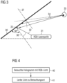
- the Fig. 4 shows a flowchart illustrating a method according to an embodiment.
- the method of Fig. 4 can be used in particular to operate the devices of the Fig. 1-3 be used.
- a holographic element is illuminated with light in three spectral colors, for example, red, green, and blue (RGB), whereby the holographic element is preferably transparent to other wavelengths.
- the holographic element then directs the light to a viewing location, whereby the holographic element can project the light onto an intermediate image, which is viewed from the viewing location (for example, as in Fig. 2 shown) or the holographic element can serve as a ground glass (for example as in Fig. 3 shown).
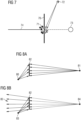
- Fig. 8A is an exposure of a holographic element 82 for data reflection, for example, according to the embodiment of the Fig. 2
- a holographic element 82 To generate a holographic element 82, an interference of two counter-propagating spherical waves is recorded on the holographic element 82, in particular within a holographic layer. These waves can be generated, for example, with a coherent laser of sufficient coherence length.
- a point light source 80 for emitting one of the spherical waves is located at the later location of the imaging device and emits a so-called reference wave, and another point light source 81 for emitting the other of the spherical waves is located at the location of the later virtual image and emits a so-called signal wave.
- the distance of the virtual image to the eyebox (i.e., essentially to the eye of a viewer) is subsequently at least approximately the sum of the distance of the point light source 80 to the holographic element 82 plus the distance of the point light source 81 to the holographic element 82.
- any desired distance of the virtual image can be realized in a later application.
- the Fig. 8B shows the application of the as in Fig. 8A exposed holographic element in an "ideal case".
- the holographic element is illuminated with reference light from a point light source 83 (corresponding to an imaging device), which leads to the formation of a virtual image 84 (corresponding to the position of the point light source 81 of the Fig. 8A ) which can be viewed by one eye (eyebox) at 85.
- a point light source 83 corresponding to an imaging device
- Fig. 8C shows a real application.
- an imaging device 86 is used, which, in contrast to a Point light source has an extension ⁇ y in the y-direction and an extension ⁇ x in the x-direction. This can lead to distortions compared to the ideal case of Fig. 8B However, these are negligible to a certain extent for practical applications, depending on the desired image quality.
- the dimensions of the imaging device are chosen to be comparatively small, and the imaging device is arranged near the location of the point light source 80.
- Fig. 9A and 9B show another case in which an 'infinite' distance of the virtual image to a viewer is realized.
- the Fig. 9A illustrates the exposure of a holographic element 90.
- a reference wave 92 is generated by a substantially point-shaped signal source 91, corresponding to the signal source 80 of the Fig. 8A
- a signal wave 93 with a parallel light beam is used here, which can be generated, for example, by a collimated, expanded laser beam.
- Fig. 9B shows the application of the holographic element 90, which as in Fig. 9
- An imaging device 95 (ideally a point source, in the real case a source as in Fig. 8C shown) illuminates the holographic element 90 from a position corresponding to a position of the signal source 91. This results in the generation of a virtual image at infinity corresponding to light rays 94, which can be viewed at a location 96.
- a holographic element as a ground glass can be done according to the Fig. 8A
- the signal wave is generated by a ground glass screen (instead of the signal source 81) located close to the holographic element.
- the holographic ground glass screen is thus recorded as a reflection hologram in exemplary embodiments.
- the shape and position of the reference source are retained and can therefore be used like the signal source 80 of the Fig. 8A at a suitable angle to the respective holographic element in order to later achieve a suitable arrangement adapted to a particular installation space.
- a virtual image is generated by means of a holographic element and a corresponding imaging device.
- a real image can also be generated.
- a corresponding modification i.e., providing a real image instead of a virtual image, can be implemented in all of the embodiments discussed, provided there is sufficient space between the viewer and the holographic element to generate the real image.
- the real image is generated between the viewer and the holographic element.
- Such devices are suitable, for example, for displaying operating elements that can then be actuated by the viewer, with conventional gesture recognition devices (e.g., cameras, distance sensors, and the like) being used to detect the actuation.
- conventional gesture recognition devices e.g., cameras, distance sensors, and the like
- the representation of the operating element e.g., head or rotary switch
- the representation of the operating element e.g., head or rotary switch
- a rotation of the rotary switch can be displayed.
- the device of the Fig. 10 comprises an imaging device 100, which can be configured like the imaging device in the embodiments discussed above, and a holographic element 101.
- the holographic element 101 When illuminated by the imaging device 100, the holographic element 101 generates a real image at a location 102, which can be viewed within a box 103.
- the real image 102 is thus generated between the viewer (at 103) and the holographic element 101.
- the Fig. 11 illustrates a manufacturing process for the holographic element 101 of the Fig. 10
- a holographic material as already discussed above, is exposed to a reference beam (or a reference wave) 111, which diverges from a location 112.
- Location 112 corresponds to the location where the imager 100 will later be arranged.
- the holographic material is exposed to a signal beam (an object wave) 110, which converges toward the location 102 of the real image.
- this exposure can be done separately for different wavelengths, for example, a red, a green, and a blue wavelength.
- a virtual or real image is displayed in a plane.
- an image display can also be carried out in multiple planes, at different angles, and/or generally at different locations.
- This can take advantage of the fact that the holographic elements used, in particular volume holograms, operate both wavelength- and angle-selectively, as already described.
- different colors can be imaged at different locations and/or viewed from different angles, for example, by selecting different directions and shapes of the reference beam and signal beam for different wavelengths during the manufacture of the holographic element.
- color images can be generated at different locations by using green and blue wavelengths that differ in wavelength by more than one sensitivity range of the hologram used.
- the working wavelengths 532 nm (green), 460 nm (blue), and 660 nm (red) can be used for a first image
- the working wavelengths 520 nm (green), 442 nm (blue), and 647 nm (red) can be used for a second image.
- a first virtual image can be generated at a first distance from the holographic element, for example 1 m, and a second image at a second distance, for example 5 m, whereby a polychromatic representation including white is possible for each of these images.
- the same can also be implemented for monochrome images with only one wavelength each.
- Image generation can be achieved with a single imager, which then produces a total of six different colors, or with separate imagers, which can also be arranged at different angles. A viewer in the eyebox then sees both contents at different distances.
- Each holographic element only sees its operating wavelengths and is otherwise transparent. Combinations with even more wavelengths and different distances are also possible.
- the same wavelengths can be used for both images, since, as mentioned, the holographic elements are also angle-selective.
- a corresponding embodiment is described in Fig. 12 shown.
- a holographic element 122 contains volume holograms for two different imagers 120, 121. Based on light from the imager 120, a virtual image is generated at a location 123, and based on light from the imager 121, a virtual image is generated at a location 124, which is another distance from the holographic element 122 than the location 122. The two virtual images can then be viewed within an eyebox 125.
- the exposure of the volume holograms for the two imagers 120, 121 can be carried out in separate layers and each as discussed above.
- the virtual images at locations 123, 124 can be viewed from the same eyebox 125, i.e., simultaneously.
- the holographic element 122 and the imagers 120 and 121 can be configured such that the virtual images can be viewed "side by side," as it were, which can effectively enlarge the eyebox.
- the design can also be such that separate images can be viewed from different positions, for example, from a driver's position and a passenger's position in a vehicle. In this way, different content can be presented to different people. Overall, it is therefore possible to provide different virtual or real images using one or more imagers, possibly with different operating wavelengths, at different locations and/or for viewing from different locations.
- a flat virtual or real image is generated using an imaging device and a holographic element.
- three-dimensional content (3D content) can also be displayed.
- separate virtual or real images are generated for the left and right eyes in correspondingly small eyeboxes. If the images are selected with different perspectives, a stereo effect can be created.
- a 3D imager may be used, enabling the display of true virtual or real three-dimensional images.
- a corresponding imager is shown in Fig. 13 shown schematically.
- the imager of the Fig. 13 comprises a planar light source 130, a spatial amplitude modulator 131, and a spatial phase modulator 132.
- the spatial amplitude modulator 131 can be used to spatially selectively modulate the amplitude of light generated by the light source 130. Examples of such spatial amplitude moderators include LCDs, micro mirror arrays (DMDs), or LCoS arrays.
- the phase of the generated light can be modulated in a spatially resolved manner.
- Corresponding spatial phase moderators are also commercially available and can be based, for example, on liquid crystal technology (e.g., LCoS).
- LCoS liquid crystal technology
- the generated light can be modulated both in terms of amplitude and phase. Since a 3D impression is caused in particular by different phases of the light reaching the eye, a three-dimensional image can be generated with such an arrangement.
- the light source 130 can also operate with limited scanning (e.g., using lasers) and can have different colors (e.g., red, green, blue) for a color display.
- Fig. 13 The imager shown can be arranged at the positions of the imagers of the embodiments discussed above.
- the artificially generated spatial 3D object is then located in the source point of the reference beam during recording (reference number 86 in Fig. 8C ) and can then be enlarged as a 3D object in the source point of the signal source (reference number 84 in Fig. 8C ) for the respective eyebox.
- This also allows the display of three-dimensional objects.
- Such three-dimensional objects can also be used to display control elements as explained above.
Landscapes
- Engineering & Computer Science (AREA)
- Physics & Mathematics (AREA)
- Chemical & Material Sciences (AREA)
- Combustion & Propulsion (AREA)
- Transportation (AREA)
- Mechanical Engineering (AREA)
- General Physics & Mathematics (AREA)
- Optics & Photonics (AREA)
- Holo Graphy (AREA)
- Diffracting Gratings Or Hologram Optical Elements (AREA)
- Instrument Panels (AREA)
Applications Claiming Priority (3)
| Application Number | Priority Date | Filing Date | Title |
|---|---|---|---|
| DE102015101687.7A DE102015101687A1 (de) | 2015-02-05 | 2015-02-05 | Verfahren und Vorrichtungen zur Dateneinspiegelung |
| EP16703116.0A EP3254152B1 (fr) | 2015-02-05 | 2016-02-04 | Dispositif pour l'incrustation de données en utilisant des éléments optiques holographiques |
| PCT/EP2016/052431 WO2016124713A2 (fr) | 2015-02-05 | 2016-02-04 | Procédé et dispositifs pour l'incrustation de données |
Related Parent Applications (2)
| Application Number | Title | Priority Date | Filing Date |
|---|---|---|---|
| EP16703116.0A Division EP3254152B1 (fr) | 2015-02-05 | 2016-02-04 | Dispositif pour l'incrustation de données en utilisant des éléments optiques holographiques |
| EP16703116.0A Division-Into EP3254152B1 (fr) | 2015-02-05 | 2016-02-04 | Dispositif pour l'incrustation de données en utilisant des éléments optiques holographiques |
Publications (2)
| Publication Number | Publication Date |
|---|---|
| EP4552893A2 true EP4552893A2 (fr) | 2025-05-14 |
| EP4552893A3 EP4552893A3 (fr) | 2025-09-03 |
Family
ID=55304996
Family Applications (2)
| Application Number | Title | Priority Date | Filing Date |
|---|---|---|---|
| EP25159190.5A Pending EP4552893A3 (fr) | 2015-02-05 | 2016-02-04 | Procédés et dispositifs d'incrustation de données |
| EP16703116.0A Active EP3254152B1 (fr) | 2015-02-05 | 2016-02-04 | Dispositif pour l'incrustation de données en utilisant des éléments optiques holographiques |
Family Applications After (1)
| Application Number | Title | Priority Date | Filing Date |
|---|---|---|---|
| EP16703116.0A Active EP3254152B1 (fr) | 2015-02-05 | 2016-02-04 | Dispositif pour l'incrustation de données en utilisant des éléments optiques holographiques |
Country Status (5)
| Country | Link |
|---|---|
| US (2) | US20180024361A1 (fr) |
| EP (2) | EP4552893A3 (fr) |
| CN (2) | CN107209395A (fr) |
| DE (1) | DE102015101687A1 (fr) |
| WO (1) | WO2016124713A2 (fr) |
Families Citing this family (20)
| Publication number | Priority date | Publication date | Assignee | Title |
|---|---|---|---|---|
| DE102015116408A1 (de) | 2015-09-28 | 2017-03-30 | Carl Zeiss Jena Gmbh | Vorrichtung zur Datenprojektion |
| DE102016113518A1 (de) | 2016-07-21 | 2018-01-25 | Carl Zeiss Jena Gmbh | Vorrichtungen zur Dateneinspiegelung |
| DE102016115938A1 (de) | 2016-08-26 | 2018-03-01 | Carl Zeiss Jena Gmbh | Wellenleiter sowie Vorrichtungen zur Dateneinspiegelung |
| JP6724995B2 (ja) * | 2016-09-21 | 2020-07-15 | 日本電気株式会社 | 表示システム |
| EP3443883B1 (fr) * | 2017-08-14 | 2020-07-29 | Carl Zeiss Vision International GmbH | Procédés et dispositif permettant d'effectuer des mesures relatives à l' oeil |
| DE102017214592A1 (de) | 2017-08-22 | 2019-02-28 | Continental Automotive Gmbh | Head-Up-Display |
| DE102018201201A1 (de) * | 2018-01-26 | 2019-08-01 | Robert Bosch Gmbh | Vorrichtung und Verfahren zur Ermittlung von Informationen mittels Hologramm in einem Kraftfahrzeug |
| US10552708B2 (en) | 2018-03-07 | 2020-02-04 | Xerox Corporation | Method and system for extracting impression marks using a mobile application |
| CN110658626A (zh) * | 2018-06-29 | 2020-01-07 | 深圳市掌网科技股份有限公司 | 头戴显示设备 |
| JP7049583B2 (ja) * | 2018-07-26 | 2022-04-07 | コニカミノルタ株式会社 | ヘッドアップディスプレイ装置 |
| DE102018212735A1 (de) * | 2018-07-31 | 2020-02-06 | Robert Bosch Gmbh | LIDAR-Vorrichtung mit mindestens einem Streuscheibenelement |
| US12336693B2 (en) | 2018-08-13 | 2025-06-24 | Sony Corporation | Medical system, medical light source apparatus, and method in medical light source apparatus |
| DE102019133624A1 (de) * | 2019-12-10 | 2021-06-10 | Bayerische Motoren Werke Aktiengesellschaft | Projektionseinheit für eine Blickfeldanzeigevorrichtung zum Einsatz in einem Fahrzeug |
| DE102021105830A1 (de) | 2021-03-10 | 2022-09-15 | Carl Zeiss Jena Gmbh | Wellenfrontmanipulator für Head-up-Display mit holographischem Element, optische Anordnung und Head-up-Display |
| US11294178B1 (en) * | 2021-08-30 | 2022-04-05 | Luminit Llc | Transparent holographic heads up display with in-plane image |
| DE102021209849A1 (de) | 2021-09-07 | 2023-03-09 | Robert Bosch Gesellschaft mit beschränkter Haftung | Projektionsvorrichtung zur Anzeige von Informationen in einem Fahrzeug |
| DE102022105038A1 (de) | 2022-03-03 | 2023-09-07 | Carl Zeiss Jena Gmbh | Wellenfrontmanipulator mit Totalreflexion und Reflexionshologramm |
| DE102022105039A1 (de) | 2022-03-03 | 2023-09-07 | Carl Zeiss Jena Gmbh | Wellenfrontmanipulator für Head-up-Display mit holographischem Element zum Erzeugen einer gekippten virtuellen Bildebene |
| DE102023111629A1 (de) | 2023-05-04 | 2024-11-07 | Carl Zeiss Jena Gmbh | Wellenfrontmanipulator zur Anordnung im Strahlengang eines Head-up- Displays mit einer holographischen Anordnung als einzigem Aberrationskorrekturelement |
| DE102024115881A1 (de) | 2024-06-06 | 2025-12-11 | Carl Zeiss Jena Gmbh | Holographische Anzeigevorrichtung mit zwei Displays zur Breitbildanzeige |
Citations (2)
| Publication number | Priority date | Publication date | Assignee | Title |
|---|---|---|---|---|
| DE102008039737A1 (de) | 2008-08-26 | 2010-04-01 | G + B Pronova Gmbh | Anzeigeeinrichtung, transparentes Abbildungselement sowie Verfahren zur Herstellung eines transparenten Abbildungselements |
| WO2014115095A2 (fr) | 2013-01-28 | 2014-07-31 | Ecole Polytechnique Federale De Lausanne (Epfl) | Film holographique transflectif pour dispositif d'affichage porté sur tête |
Family Cites Families (13)
| Publication number | Priority date | Publication date | Assignee | Title |
|---|---|---|---|---|
| US4790613A (en) * | 1987-01-06 | 1988-12-13 | Hughes Aircraft Company | Holographic display panel for a vehicle windshield |
| US5112121A (en) * | 1989-03-21 | 1992-05-12 | Chang David B | Display system for multiviewer training simulators |
| US5291316A (en) * | 1991-09-27 | 1994-03-01 | Astronautics Corporation Of America | Information display system having transparent holographic optical element |
| JP3151766B2 (ja) * | 1992-07-31 | 2001-04-03 | キヤノン株式会社 | 画像表示装置 |
| DE19927712A1 (de) * | 1998-12-02 | 2000-06-08 | Hsm Gmbh | Holografisches Display-System zur Darstellung von Information |
| DE19930710C2 (de) * | 1999-07-02 | 2003-06-12 | Eads Deutschland Gmbh | Bilddarstellungssystem und -verfahren für Fahrzeuge |
| US7503656B2 (en) * | 2003-05-06 | 2009-03-17 | Koninklijke Philips Electronics, N.V. | Projection device for simultaneously generating a plurality of mutually spaced, holographic frames of one and the same image by means of a holographic screen |
| US7418170B2 (en) * | 2004-03-29 | 2008-08-26 | Sony Corporation | Optical device and virtual image display device |
| CN101226325B (zh) * | 2008-02-03 | 2010-06-02 | 李志扬 | 基于随机相长干涉的三维显示方法及装置 |
| JP5462443B2 (ja) * | 2008-03-27 | 2014-04-02 | 株式会社東芝 | 反射スクリーン、表示装置及び移動体 |
| RU2378673C1 (ru) * | 2008-04-03 | 2010-01-10 | Владимир Исфандеярович Аджалов | Способ визуализации изображений и устройство для его реализации |
| DE102011083662B4 (de) * | 2011-09-29 | 2022-02-17 | Robert Bosch Gmbh | Anzeigevorrichtung für einen Insassen eines Fahrzeugs, Fahrzeug und Verfahren zur Generierung einer Anzeige in einem Sichtfeld des Insassen |
| GB2499579B (en) * | 2012-02-07 | 2014-11-26 | Two Trees Photonics Ltd | Lighting device |
-
2015
- 2015-02-05 DE DE102015101687.7A patent/DE102015101687A1/de active Pending
-
2016
- 2016-02-04 EP EP25159190.5A patent/EP4552893A3/fr active Pending
- 2016-02-04 CN CN201680009120.5A patent/CN107209395A/zh active Pending
- 2016-02-04 EP EP16703116.0A patent/EP3254152B1/fr active Active
- 2016-02-04 US US15/545,873 patent/US20180024361A1/en not_active Abandoned
- 2016-02-04 CN CN202210839643.XA patent/CN115145039A/zh active Pending
- 2016-02-04 WO PCT/EP2016/052431 patent/WO2016124713A2/fr not_active Ceased
-
2022
- 2022-11-23 US US17/993,535 patent/US11977227B2/en active Active
Patent Citations (2)
| Publication number | Priority date | Publication date | Assignee | Title |
|---|---|---|---|---|
| DE102008039737A1 (de) | 2008-08-26 | 2010-04-01 | G + B Pronova Gmbh | Anzeigeeinrichtung, transparentes Abbildungselement sowie Verfahren zur Herstellung eines transparenten Abbildungselements |
| WO2014115095A2 (fr) | 2013-01-28 | 2014-07-31 | Ecole Polytechnique Federale De Lausanne (Epfl) | Film holographique transflectif pour dispositif d'affichage porté sur tête |
Also Published As
| Publication number | Publication date |
|---|---|
| WO2016124713A3 (fr) | 2016-09-22 |
| EP4552893A3 (fr) | 2025-09-03 |
| CN115145039A (zh) | 2022-10-04 |
| CN107209395A (zh) | 2017-09-26 |
| DE102015101687A1 (de) | 2016-08-11 |
| EP3254152B1 (fr) | 2025-04-02 |
| US11977227B2 (en) | 2024-05-07 |
| EP3254152A2 (fr) | 2017-12-13 |
| US20230168503A1 (en) | 2023-06-01 |
| US20180024361A1 (en) | 2018-01-25 |
| WO2016124713A2 (fr) | 2016-08-11 |
Similar Documents
| Publication | Publication Date | Title |
|---|---|---|
| EP3254152B1 (fr) | Dispositif pour l'incrustation de données en utilisant des éléments optiques holographiques | |
| DE112015002814B4 (de) | Anzeigevorrichtung für virtuelle Bilder | |
| DE112017006376B4 (de) | Blickfeldanzeigevorrichtung | |
| DE112018000274B4 (de) | Anzeigevorrichtung | |
| EP3593192B1 (fr) | Dispositif d'affichage et procédé de projection d'informations d'affichage dans un véhicule | |
| DE19930710C2 (de) | Bilddarstellungssystem und -verfahren für Fahrzeuge | |
| DE102015104085B4 (de) | Bildgebungseinrichtung und Vorrichtung zur Dateneinspiegelung | |
| DE102014215453A1 (de) | Head-up-anzeigevorrichtung | |
| WO1997016757A1 (fr) | Dispositif pour la representation d'une premiere image dans une deuxieme image visible a travers une vitre transparente | |
| DE102012107424A1 (de) | Head-Up-Displayeinrichtung, Bildschirmelement, Herstellungsverfahren dafür, und Bildprojektionsverfahren | |
| WO1998035260A1 (fr) | Ecran d'affichage holographique pour aeronefs et vehicules | |
| DE102012109569A1 (de) | Head-Up-Display-Vorrichtung | |
| DE112014000691T5 (de) | Head-up-Display-Vorrichtung | |
| WO2018015496A1 (fr) | Dispositifs d'incrustation de données | |
| DE112014003428T5 (de) | Head-up-Anzeigevorrichtung | |
| DE112014000695T5 (de) | Head-up-Display-Vorrichtung | |
| DE102017222621A1 (de) | Projektionsvorrichtung mit einer Bilderzeugungseinheit | |
| DE102014217180A1 (de) | Bilderzeugungsvorrichtung für ein Head-up-Display, Head-up-Display und Verfahren zum Erzeugen eines Bilds für ein Head-up-Display | |
| DE102018221438A1 (de) | Projektionsvorrichtung, Mikroscanner sowie Datenbrille | |
| DE112017006057T5 (de) | Mehrtiefe augmented realitätsanzeige | |
| DE102021111228A1 (de) | Holographische Projektoren mit Größenkorrektur und Ausrichtung von Strahlen mit unterschiedlichen Lichtwellenlängen | |
| DE102017223273B4 (de) | Projektionsvorrichtung aufweisend ein Hologramm, sowie Verfahren | |
| DE102016111119A1 (de) | Laser-Projektionsanordnung und Verfahren zur Erzeugung virtueller Bilder | |
| DE102023102623B3 (de) | Multiuser-Blickfeldanzeigevorrichtung, Verfahren und Steuereinheit zu dessen Betrieb sowie Fahrzeug | |
| WO2021105130A1 (fr) | Affichage tête haute à réalité augmentée |
Legal Events
| Date | Code | Title | Description |
|---|---|---|---|
| PUAI | Public reference made under article 153(3) epc to a published international application that has entered the european phase |
Free format text: ORIGINAL CODE: 0009012 |
|
| STAA | Information on the status of an ep patent application or granted ep patent |
Free format text: STATUS: THE APPLICATION HAS BEEN PUBLISHED |
|
| REG | Reference to a national code |
Ref country code: DE Ref legal event code: R079 Free format text: PREVIOUS MAIN CLASS: B60K0035290000 Ipc: G02B0027010000 |
|
| AC | Divisional application: reference to earlier application |
Ref document number: 3254152 Country of ref document: EP Kind code of ref document: P |
|
| AK | Designated contracting states |
Kind code of ref document: A2 Designated state(s): AL AT BE BG CH CY CZ DE DK EE ES FI FR GB GR HR HU IE IS IT LI LT LU LV MC MK MT NL NO PL PT RO RS SE SI SK SM TR |
|
| RIC1 | Information provided on ipc code assigned before grant |
Ipc: B60K 35/29 20240101ALI20250508BHEP Ipc: B60K 35/21 20240101ALI20250508BHEP Ipc: G02B 27/01 20060101AFI20250508BHEP |
|
| PUAL | Search report despatched |
Free format text: ORIGINAL CODE: 0009013 |
|
| AK | Designated contracting states |
Kind code of ref document: A3 Designated state(s): AL AT BE BG CH CY CZ DE DK EE ES FI FR GB GR HR HU IE IS IT LI LT LU LV MC MK MT NL NO PL PT RO RS SE SI SK SM TR |
|
| RIC1 | Information provided on ipc code assigned before grant |
Ipc: G02B 27/01 20060101AFI20250729BHEP Ipc: B60K 35/21 20240101ALI20250729BHEP Ipc: B60K 35/29 20240101ALI20250729BHEP |
|
| STAA | Information on the status of an ep patent application or granted ep patent |
Free format text: STATUS: REQUEST FOR EXAMINATION WAS MADE |
|
| STAA | Information on the status of an ep patent application or granted ep patent |
Free format text: STATUS: EXAMINATION IS IN PROGRESS |
|
| 17P | Request for examination filed |
Effective date: 20260303 |
|
| 17Q | First examination report despatched |
Effective date: 20260330 |