EP4552942A1 - Véhicule de travail, son utilisation et procédé de rénovation de voies ferrées - Google Patents
Véhicule de travail, son utilisation et procédé de rénovation de voies ferrées Download PDFInfo
- Publication number
- EP4552942A1 EP4552942A1 EP23209383.1A EP23209383A EP4552942A1 EP 4552942 A1 EP4552942 A1 EP 4552942A1 EP 23209383 A EP23209383 A EP 23209383A EP 4552942 A1 EP4552942 A1 EP 4552942A1
- Authority
- EP
- European Patent Office
- Prior art keywords
- trough
- work
- track
- tilting
- carriage
- Prior art date
- Legal status (The legal status is an assumption and is not a legal conclusion. Google has not performed a legal analysis and makes no representation as to the accuracy of the status listed.)
- Withdrawn
Links
Images



Classifications
-
- E—FIXED CONSTRUCTIONS
- E01—CONSTRUCTION OF ROADS, RAILWAYS, OR BRIDGES
- E01B—PERMANENT WAY; PERMANENT-WAY TOOLS; MACHINES FOR MAKING RAILWAYS OF ALL KINDS
- E01B27/00—Placing, renewing, working, cleaning, or taking-up the ballast, with or without concurrent work on the track; Devices therefor; Packing sleepers
- E01B27/04—Removing the ballast; Machines therefor, whether or not additionally adapted for taking-up ballast
-
- B—PERFORMING OPERATIONS; TRANSPORTING
- B61—RAILWAYS
- B61D—BODY DETAILS OR KINDS OF RAILWAY VEHICLES
- B61D9/00—Tipping wagons
-
- E—FIXED CONSTRUCTIONS
- E01—CONSTRUCTION OF ROADS, RAILWAYS, OR BRIDGES
- E01B—PERMANENT WAY; PERMANENT-WAY TOOLS; MACHINES FOR MAKING RAILWAYS OF ALL KINDS
- E01B27/00—Placing, renewing, working, cleaning, or taking-up the ballast, with or without concurrent work on the track; Devices therefor; Packing sleepers
- E01B27/02—Placing the ballast; Making ballastway; Redistributing ballasting material; Machines or devices therefor; Levelling means
Definitions
- the invention relates to a track-bound work car, its use and a method for rehabilitating a track.
- the two-way tipping wagon is equipped with a tipping mechanism for tipping the trough to the right or left side of the track.
- the trough has openable side walls parallel to the track and end walls perpendicular to the track. It also has bearing points on the underside for connecting the trough to the wagon frame at the open side wall intended for tipping, forming a tipping bearing.
- the transport wagons with the troughs can be used to reload new material at an interim storage facility and then transported along the tracks to the track construction site. There, the new material is unloaded/tipped to the side and installed on the adjacent track at the construction site using construction equipment. After the track has been laid, a final step is required to ballast the track. This involves placing backfill ballast layer by layer between the sleepers, centrally and laterally, up to the standard bedding profile. is installed.
- backfill ballast wagons are used, which are moved along the new track and have a backfilling device at the beginning, middle, or end of the wagon to lower the backfill ballast into the so-called track grid for backfilling the track or for installation in the track, and to the side of the track.
- the backfill ballast is installed both on the sides of the rails (track side areas) and centrally between the rails (track center area), usually while the wagons are moving forward.
- a track-bound work car comprises a car frame and wheel sets for moving the work car on a track. It has at least one trough with two openable side walls. and two end walls; the trough is arranged on the wagon frame. At least one tipping device is connected to the trough and the wagon frame, which provides a first tipping axis and a second tipping axis parallel to the side walls between the trough and the wagon frame. The first tipping axis and the second tipping axis are each assigned to one of the two side walls, so that the trough can be tipped by means of the tipping device optionally via one of the side walls, i.e.
- At least a first of the two end walls of the trough in the work wagon can also be opened (openable), wherein the tipping device provides at least a third tipping axis between the trough and the wagon frame, which is assigned to the first end wall and parallel to it.
- the tipping device provides at least a third tipping axis between the trough and the wagon frame, which is assigned to the first end wall and parallel to it.
- the trough can additionally be tipped via the openable end wall or third tipping axis, so that the work wagon is designed at least as a three-way tipping wagon.
- This allows bulk material loaded into the trough of the track-bound work car to be unloaded not only to the side of the track, but also into the track.
- This allows the track-bound work car to perform not only the functions of transporting bulk material on the track and unloading it to the side, but also the functions of installing bulk material into the track.
- the second of the two end walls can also be designed to be openable, and the tipping device can additionally provide a fourth tipping axis which is associated with the second end wall and parallel thereto, so that the trough can be tipped by means of the tipping device via the fourth tipping axis and the work vehicle is designed as a four-way tipping vehicle.
- the tipping device can have at least one lifting device that is arranged on the cart frame and engages with the trough.
- the trough can have bearing points on its underside that are assigned to the side walls and the end walls, which can each be connected to correspondingly arranged receiving points on the cart frame to form a tipping bearing.
- the first or second tipping axis is provided by connecting the bearing point(s) assigned to the respective side wall with the corresponding receiving point(s) on the cart frame.
- the third or fourth tipping axis is correspondingly provided by Connection of the bearing point(s) assigned to the respective end wall with the corresponding receiving point(s) on the wagon frame is provided.
- the work car can have at least two troughs arranged one behind the other in the longitudinal direction on the car frame and which can be tilted independently of one another by at least one of the tilting devices via one of the tilting axes. This creates additional application possibilities for unloading onto or next to the track.
- the work car according to the invention has at least one backfilling device designed to install backfill ballast into at least one track side area and/or a track center area. It is associated with the openable end wall, through which the trough is unloaded by tipping.
- this or each backfilling device can be detachably or adjustably attached to the carriage frame of the work carriage according to the invention, thereby providing variable positioning of the backfilling device relative to the trough and/or the track.
- the backfilling device can be mounted on the carriage frame in front of or behind the trough at a distance adapted to the opening angle of the respective end wall, and can be adapted to the track to be backfilled with regard to the installation locations of the backfill ballast, for example, in terms of width.
- the backfilling device can have at least one outlet opening whose cross-section can be varied to control the amount of backfill gravel installed. This refers to a change in the cross-sectional dimensions of the opening or, in the case of multiple outlet openings, their partial closure.
- the filling device can be controlled manually or electrically, hydraulically or pneumatically, manually or partially or fully automatically by a control device, which is preferably connected to at least one recording unit for a paving parameter that is relevant for the amount of gravel to be laid, such as a gravel requirement in the respective track areas or a speed of the work car during backfilling.
- a control device which is preferably connected to at least one recording unit for a paving parameter that is relevant for the amount of gravel to be laid, such as a gravel requirement in the respective track areas or a speed of the work car during backfilling.
- the openable side or end walls can define one or more openings that can be closed by at least one pendulum wall section, folding wall section, or pendulum-folding wall section.
- the openable end wall, to which the filling device is assigned can preferably be designed so that its opening cross-section can be varied in order to control the amount of gravel supplied when the filling device is tipped.
- the end wall can, for example, be divided into several openable sections.
- the openable end wall, to which the filling device is assigned can be designed as a pendulum wall, in which the opening cross-section can be easily varied via the opening angle.
- the work carriage according to the invention comprises a dust containment device with a fluid supply and at least one discharge opening designed to discharge fluid toward an unloading point, which is provided when the trough is tipped over the first tilting axis, the second tilting axis, or the at least third tilting axis.
- the fluid supply can be connected to a fluid reservoir located on the work carriage.
- the fluid supply can be connected to a fluid line that can be connected to a fluid reservoir on another rail-bound carriage that is coupled to the work carriage directly or indirectly via other rail-bound carriages arranged therebetween.
- Fluid supply is understood here to mean a supply device comprising at least one line, a fluid conveying means, and corresponding connections.
- at least one of the discharge openings can be assigned to each tilting axis.
- each tilting axis can be assigned a plurality of discharge openings, e.g., nozzles, which can be operated separately for discharging fluid toward the unloading point via the respective assigned tilting axis.
- the dust containment device has nozzles for discharging fluid toward each possible unloading point of the trough. It can be provided that, when unloading via one of the tilting axes, only the nozzles assigned to the same tilting axis are controlled for discharging fluid.
- the dust containment device can be permanently installed on the work carriage or can be designed as an equipment element for detachable attachment to the work carriage, so that the dust containment device is only mounted on the work carriage when required, i.e. when a dust-generating bulk material is present, whereby the work carriage can have corresponding mounting points and connections for easy installation.
- the dust containment device is designed as an optional equipment element.
- the dust containment device with at least one discharge opening, e.g., with multiple nozzles, is designed to be assigned to one of the tilting axes provided for tipping the trough to provide the unloading point.
- the dust containment device designed as an optional equipment element has nozzles for only one unloading point, with the nozzles being assigned to the tilting axis via which the trough is to be unloaded when the work vehicle is equipped with the dust containment device.
- the work carriage according to the invention can be provided by a work module that is arranged on an existing rail-bound transport carriage.
- the transport carriage provides the carriage frame with a transport surface and the wheel sets for moving the work carriage on a track.
- the work module has a support base on which the at least one trough and the tipping device of the work carriage are arranged.
- the support base arranged on the transport surface is considered to be part of the carriage frame with regard to the tipping device, wherein, for example, the lifting device and the receiving points for forming the tipping bearings are located on the support base.
- An inventive use of the track-bound work car according to the invention provides, on the one hand, for the transport of bulk material in the trough and, on the other hand, for the unloading of the bulk material next to the track by tipping the trough over the first tipping axis or the second tipping axis or for the installation of the bulk material in the track by tipping the trough over the third tipping axis.
- steps a) to c) can be repeated in the first construction phase and steps A) to C) in the second construction phase, if necessary several times.
- the invention relates to a track-bound work car and its use in a track rehabilitation process.
- the work car is not only suitable for transporting excavated material, bulk materials, and bulk goods, but also includes the function of backfilling a track.
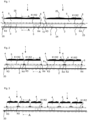
- the figures show examples of a work car 1 according to the invention, each having a car frame 2 and wheel sets 3 for traveling on a track 20.
- the track 20 is shown in the figures only by means of the rails 23 and sleepers 24; the ballast bed and the underlying formation protection layer and formation substructure are omitted for clarity.
- the track-bound work car 1 can be connected via a car coupling 15 to another work car 1, such as in Fig. 1 to 3 , 7 to 9 , 11 to 14 , 25 shown, or with railway carriages of other types as in Fig. 26 shown, can be connected to form a wagon train that can be moved by at least one tractor over track 20.
- the representation in some figures with two work wagons 1 arranged one behind the other is not intended to represent a restriction; of course, it is also possible to use the work wagon 1 alone or in a wagon train with more than two work wagons 1.
- a trough 4 for receiving bulk material 25 is arranged, which can be, for example, excavated material from a track construction site such as old ballast or soil or new construction material intended for installation such as new ballast or backfill ballast.
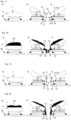
- the trough 4 has two openable side walls 5 and two openable end walls 6 and is connected to the wagon frame 2 via a tipping device, which provides four tipping axes K1, K2, K3, K4 for tipping the trough 4.
- a first tipping axis K1 and a second tipping axis K2 run parallel to the side walls 5, i.e. approximately parallel to the track 20 or its rails 23 as in Fig.
- first tilt axis K1 of the Fig. 4 right side wall 5 and the second tilting axis K2 is assigned to the left side wall 5.
- the trough 4 can be tilted optionally via the first tilting axis K1 ( Fig. 5 ) or via the second tilting axis K2 ( Fig. 6 ) so that the bulk material 25 is discharged from the trough 4 to the right or left of the track 20.
- a third tilting axis K3 and a fourth tilting axis K4 run parallel to the end walls 6, i.e. transverse to the track 20 and parallel to the sleepers 24, respectively, as in Fig. 4 is indicated, whereby the third tilting axis K3 of the Fig. 1 left end wall 6, which is defined here as the rear end wall 6, and the fourth tilting axis K4 is assigned to the right, hence front, end wall 6.
- the trough 4 can be tilted either via the third tilting axis K3 or via the fourth tilting axis K4 in the direction of the track 20, so that the bulk material 25 is discharged from the trough 4 to the rear or front into the track 20, as well as Fig. 7 to 10 can be removed.
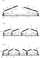
- FIG. 7 shows the left working carriage 1 tipped over the third tipping axis K3, so that the bulk material 25 from the trough 4 is tipped backwards (into the drawing plane in Fig. 10 ) is unloaded into track 20.
- the right work car 1 in Fig. 7 is shown with the trough 4 tilted over the fourth tilting axis K4, so that the bulk material 25 is unloaded from the trough 4 into the track 20 at the front.
- an alternative work car 1 it is possible for an alternative work car 1 according to the invention to have only one of the end walls 6 designed to be openable and for the tipping device to provide only three tipping axes K1, K2, K3, so that the trough 4 can be tipped either to the right or left next to the track 20 via the first or second tipping axis K1, K2 or in the direction of the track 20 via the third tipping axis K3.
- a variation of the unloading direction in the direction of the track 20 to the front or rear is nevertheless possible by placing the work car 1 with the openable end wall 6 to the front or rear when assembling a wagon train.
- the work trolley 1 shown has two or three troughs 4 which are arranged one behind the other in the longitudinal direction on the trolley frame 2. For the sake of clarity, not all details are shown there, but are readily apparent due to the similarity to the work trolley 1 with one trough 4.
- the above and following statements regarding the work trolley 1 with a single trough 4 on the trolley frame 2 apply accordingly to the work trolleys 1 with two or more troughs 4 on the trolley frame 2.
- the troughs 4 of a work trolley 1 can be tipped independently of one another by means of a respective tipping device, optionally via a tipping axis K1, K2 of the side walls 5 or a tipping axis K3, K4 of the openable front wall 6.
- the two troughs 4 of the right-hand work vehicle 1 are tilted in the opposite direction, i.e., the left trough 4 is tilted to the right or forward via the fourth tilting axis K4, and the right trough 4 is tilted to the left/back via the third tilting axis K3.
- the two troughs 4 of the right-hand work vehicle 1 are unloaded at the same unloading point in the middle of the right-hand work vehicle 1.
- the two outer troughs 4 are each tilted to the right or forward via the fourth tilting axis K4, and the middle trough 4 is shown tilted to the left/backward via its third tilting axis K3, so that the left and middle troughs 4 of the right work car 1 have a common unloading point in the rear third of the right work car 1, while the unloading point of the right trough 4 onto track 20 is in front of the right work car 1.
- the tipping device for tipping the trough 4 has, in the figuratively illustrated examples, a lifting device 7 which is arranged on the vehicle frame 2 and engages with the trough 4.
- a tipping device can have more than one lifting device 7.
- the lifting device 7 can, for example, be a multi-stage hydraulic telescopic cylinder as in Fig. 5, 6 shown, or another lifting device known from the state of the art can be used. In Fig. 7 to 9 , 11 to 14 , 17 to 20 the lifting device 7 is merely indicated by a rectangle.
- the lifting device 7 can, for example, have a ball socket (not shown figuratively) to form a ball joint with the trough 4, which allows the trough 4 to be tilted in different directions during the stroke.
- the tipping device comprises bearing points 8 on the underside 4' of the trough 4 and correspondingly arranged receiving points 8' on the carriage frame 2 (shown in Fig. 5, 6 ), which can be connected to form a tilting bearing 9 to provide one of the tilting axes K1, K2, K3, K4.
- the bearing points 8 on the underside 4' of the trough 4 are assigned to the side walls 5 and the end walls 6.
- more than one tilting bearing 9 is preferably provided, for which purpose two or possibly more bearing points 8 per side and end wall 5, 6 can be formed on the underside 4' of the trough 4 and the corresponding receiving points 8' on the carriage frame 2.
- the bearing points 8 or the receiving points 8' can be designed as tilting bushings, which can be connected to form a tilting bearing 9 by means of a plug pin.
- Fig. 5 The bearing and receiving points assigned to the right side wall 5 are connected to a tilting bearing 9, which provides the first tilting axis K1. All other bearing and receiving points are not connected, as can be seen from the bearing point 8 assigned to the left side wall 5 on the underside 4' of the trough 4, which is not connected to the correspondingly arranged receiving point 8' on the carriage frame 2. Under the influence of the lifting device 7, the trough 4 tilts accordingly to the right and is tilted via the first tilting axis K1. Fig.
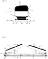
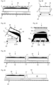
- Fig. 11 to 16 illustrate examples of a work car 1 with filling devices 10 for installing backfill ballast 25 in the track 20.
- the work car 1 with a trough 4 in Fig. 11 has a filling device 10 with two side filling devices 10a for each of the two track side areas 21 and two central filling devices 10b for the track center area 22, as shown in Figs. 15 and 16 can be seen.
- the filling device 10 is assigned to the openable end wall 6, over which the trough 4 is tipped, and is fastened to the wagon frame 2 in such a way that the filling ballast 25 located in the trough 4 flows over the openable end wall 6 into the filling device 10 when the trough 4 is tipped.
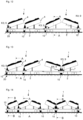
- a work carriage 1 with more than one trough 4 allows different arrangements of filling devices 10, as the examples in Fig. 12 to 14 show, and thus an adaptation of the work car 1 to the backfill ballast requirement in the track 20.
- a work car 1 with two troughs 4 or three troughs 4 with separate unloading points for each trough 4 can have an associated backfilling device 10, as in Fig. 12 using both work cars 1 and in Figs. 13 and 14 can be seen on the left work carriage 1.
- the associated filling device 10 is arranged in front of or behind the trough 4 on the carriage frame 2.
- a common backfilling device 10 can be used, which is designed accordingly for the installation of backfill gravel 25 from two troughs 4 one after the other or simultaneously.
- the attachment of the backfilling devices 10 to the wagon frame 2 is detachable, adjustable, or both, in order to position the backfilling devices 10 in relation to the track 20 into which the backfill ballast 25 is installed, in accordance with the tipping area or unloading point of the trough 4.
- the amount of ballast allowed through for installation can be varied and thus metered.
- the opening cross-section of an outlet opening 10' of the backfilling device 10 can be varied.
- the cross-section or diameter of the opening 10' can be enlarged or reduced, e.g., by means of slides or panels or the like, in order to be able to introduce the backfill ballast quantities into the track in a targeted and metered manner.
- a backfilling device can have various outlet openings that can be selected for use, or the number of open outlet openings of a backfilling device with multiple outlet openings can be varied.
- the lateral and central filling devices 10a, 10b also called ballast hoses, can be controlled in combination or individually, so that the installed amount of ballast can be continuously regulated to precisely match the ballast requirement in the respective track section 21, 22.
- the backfill ballast 25 can be unloaded in a targeted, metered, and precise manner between the rails 23 or next to the rails 23 and filled into the track 20 from above.
- These backfilling devices 20 can be manually or electrically controlled, semi-automated electrically, fully automated electrically, or hydraulically or otherwise controlled.
- a corresponding control device (not shown in the figure) can be connected to at least one recording unit in the case of partial or full automation, which records a flow rate-relevant installation parameter for the backfill ballast 25. This can be, for example, the speed of the work car 1 or the ballast requirement in the respective track section, which is determined by an actual profile of the ballast bed that deviates from the ballast control profile.
- FIG. 17 to 20 The work carriage 1 with the trough 4 is shown in a) non-tipped transport position, b) tilted position via the first tilting axis K1 and c) tilted position via the second tilting axis K2.
- the side walls 5 are designed as folding walls 5, so that the material 25 is unloaded further away from the track 20 when tipping than when the side walls 5 are designed as pendulum walls 5, as in Figs. 19 and 20 shown. Therefore, by selecting the opening variant, the distance between the unloading point and the trough 4 can be varied.
- the pendulum wall also offers the possibility of controlling the material throughput during unloading through the opening cross-section, which can be adjusted via the opening angle of the pendulum wall.
- the openable end walls 6 can also be designed as a pendulum wall or folding wall in a corresponding manner, so that the following embodiments also apply to the end walls 6 in a corresponding modification.
- the design of the end wall 6 as a pendulum wall can be preferred, which, with an adjustable opening angle, enables precise dosing during feeding by tipping the backfill gravel 25 into the filling device 10.
- the opening angle of the end wall 6 designed as a pendulum wall as well as a tilt angle of the trough 4 can be set by the control unit a partially or fully automatic version or recorded by a recording unit.
- the trough 4 has a folding bearing 12' on the bottom of each side wall 5 and a locking device 13 in the upper edge area, which is closed in the transport position a) and open or released in the tilted position b), c).
- the locking device 13 can be engaged with a receiving point 14 of the side wall 5.
- the locking device 13 can be engaged with a receiving point 14 of the side wall 5.
- each side wall 5 of the trough 4 of the Fig. 17 to 20 can be designed as pendulum folding walls that can be opened optionally as a folding wall or a pendulum wall, wherein the locking devices 13 are provided by bearing points 13 that are designed to be connected to the receiving points 14 for the pendulum bearing 12 in the upper edge region and for the folding bearing 12' on the floor.
- each side wall 5 has receiving points 14 on its front edge regions that border on the end walls 6, on the floor side and in the upper edge region.
- the locking devices/bearing points 13 are arranged on the lateral edge regions of each end wall 6 on the floor side and in the upper edge region, wherein a pendulum wall is formed when the bearing points 13 and receiving points 14 in the upper edge region are connected to a pendulum bearing 12 and the floor-side bearing points 13 and receiving points 14 are released.
- a folding wall is created when, conversely, the floor-side bearing points 13 and receiving points 14 are connected to form a folding bearing 12' and the bearing points 13 and receiving points 14 are released in the upper edge area.
- Each wall section can be designed as a swing wall, folding wall or swing-folding wall as described above, wherein the corresponding bearing points or locking devices and receiving points for forming a swing and/or folding bearing are present on the wall areas of the side or end walls 5, 6 and the wall sections that delimit the opening.
- FIG. 21 to 26 Examples of different designs of a work carriage 1 according to the invention with a device for dust containment 16 are shown.
- This device has a fluid supply 17 and nozzles 18, which are arranged, for example, on a frame construction above the side walls 5 and end walls 6 of the trough 4.
- the nozzles 18 are arranged or aligned such that a fluid fed through the fluid supply, such as water, is discharged through the nozzles in the direction of an unloading point as a spray mist or spray curtain 18'.
- the unloading point in Fig. 23 is located to the right of track 20 and is provided by tipping the trough 4 over the first tipping axis K1.
- a spray curtain 18' is generated by means of the nozzles 18, which are arranged above the tipped side wall 5, i.e., are assigned to the first tipping axis K1.
- Fig. 24 shows a work car 1 tilted over the third tilting axis K3 during the unloading of the bulk material 25 into the middle and side areas of the track 20 by means of corresponding filling devices 10a, 10b according to Fig. 16
- Fig. 24 a dust containment device 16 for a spray curtain 18', which is generated by the nozzles 18 assigned to the third tilting axis K3 above the tilted end wall 6.
- the fluid supply 17 of the dust containment device 16 comprises a conveying means for the fluid, e.g. a pump, from which a line leads to the nozzles 18. Furthermore, the fluid supply 17 in the example of Fig. 25 connected via a line 17' to a fluid reservoir 19, which is arranged on the same work carriage 1 - here below the trough 4 in the area of the carriage frame 2. Alternatively, such a fluid reservoir can also be arranged next to or on the trough 4 (not shown). Another alternative is shown in Fig. 26 shown, wherein the fluid supply 17 of the dust containment device 16 is connected via a line 17' to a fluid reservoir 19 provided by a rail-bound tank car 19' coupled to the work car 1.
- a conveying means for the fluid e.g. a pump
- the dust containment device 16 can be designed as an optional feature for placement on the work carriage 1, so that the work carriage 1 is only equipped with the device 16 when needed.
- the device 16 may not be equipped with nozzles 18 for each tiltable side and end wall 5, 6, but may instead simply provide nozzles for placement above the respective side or end wall 5, 6 intended for tilting.
- the fluid supply 17 may have a fluid connection for easy connection to the line 17'.
- the orientation of the nozzles 18 with respect to the unloading point can be related to the trough 4 or to the wagon frame 2, depending on whether the device 16 is connected to the trough 4 or arranged statically on the work wagon 1. If the device 16 is coupled to the trough 4 as shown, so that the nozzles 18 directed towards the unloading point are pivoted during tipping, the relative position and orientation of the nozzles 18 with respect to the trough 4 always remain the same. The orientation of the nozzles is then relative to the trough 4. Alternatively, the orientation of the nozzles is related to the wagon frame if the device 16 is attached to the wagon frame 2 and the position of the nozzles does not change when the trough is tipped. It would also be conceivable for the orientation of the nozzles to be determined on site depending on the flow properties of the bulk material during unloading and, if applicable, any existing track gradient at the unloading point.
- the work carriage 1 can be designed as a completely independent construction comprising wheel sets 3, carriage frame 2 and trough 4 with tipping device.
- the work carriage 1 can be designed as in Fig. 27 shown, be designed as a superstructure system, wherein a correspondingly designed work module 1' is mounted on a commercially available basic carriage construction such as a conventional transport carriage 3'.
- This conventional carriage 3' has the carriage frame 2 and the wheel sets 3 as well as a transport surface assigned to the carriage frame 2, on which the work module 1' is arranged, which - here - has a trough 4 with a tilting device, which is arranged on a support base 2'.
- the work module 1' can be designed corresponding to the previously described work carriage 1, wherein the receiving points 8' for forming the tilting bearings 9 are present on the support base 2', which, after the module 1' has been arranged on the transport surface of the transport carriage 3', is stationary in relation to the carriage frame 2 and therefore in the present context can be functionally regarded as part of the carriage frame 2.
- the work car 1 can be used to transport bulk material in the trough 4 and to unload the bulk material next to the track 20 by tilting the trough 4 sideways about one of the tilting axes K1, K2 parallel to the side wall or by tilting the trough 4 in the direction of the track 20 about one of the tilting axes K3, K4 parallel to the end wall, in particular in conjunction with a backfilling device 10 for installing backfill ballast 25 in the track center and side areas 22, 21.
- the method for rehabilitating a track 20 in at least two construction phases I, II using at least one work car 1 is described in Fig. 28 outlined and includes, in the first construction phase I, the removal of excavated material 25 that accrues at a rehabilitation site of the track 20 to be renovated.
- the work car 1 (the work cars 1) are provided at the rehabilitation site on a second track 20 adjacent to the track 20 to be renovated and the trough(s) 4 are loaded with the excavated material 25.
- step b) the work car 1 (the work cars 1) are moved with the excavated material 25 from the rehabilitation site to an interim or final storage facility, where in step c) the trough(s) 4 are unloaded next to the track 20 by tipping the trough 4 over the first or second tipping axis K1, K2, as in Fig. 5, 6 and also in Figs. 18, 20 can be seen.
- Step d) refers to the optional repetition of steps a) to c) and comprises the movement of the work car 1 (the work car 1) unloaded at the interim storage facility onto the second track 20 at the rehabilitation site until the excavation work at the rehabilitation site is completed.
- the work car(s) 1 will be deployed at the rehabilitation site to fill the rehabilitated track 20 with backfill ballast 25.
- the work car(s) 1 will be provided at a new material storage facility, and the trough(s) 4 will be loaded with backfill ballast 25. Loading equipment such as excavators or wheel loaders will be used for this purpose.
- the new material storage facility can be located at the same or a different location as the interim storage facility in construction phase I.
- step B the work car(s) 1 with the backfill ballast 25 will be moved from the new material storage facility to the rehabilitation site, now on the already rehabilitated track 20.
- step C the trough(s) 4 will be tipped over the third tipping axle K3, and the backfill ballast 25 will be installed into track 20. as in the Fig. 7 to 10 , and using filling devices 10 in Fig. 11 to 16 is shown.
- the backfill ballast 25 is installed in layers between the sleepers 24, centrally and laterally, up to the standard bedding profile.
- the backfill ballast 25 falls from above into the so-called track grid and is preferably filled/introduced into both the track side areas 21 and the track center area 22 during forward movement across the track.
- work car 1 can also be used to transport other new materials such as gravel/roadside material/ballast during track rehabilitation.
- work car 1 is also loaded with the new material at an intermediate or new material storage facility, but the transport to the rehabilitation site takes place on the adjacent track 20, and unloading is performed by tipping over the first or second tipping axle K1, K2 next to track 20.
- the Work Car 1 can thus be used for different work steps in various construction projects during different construction phases. This reduces the investment and maintenance costs for a car operator, as well as the direct installation costs on the construction site. Furthermore, the logistical handling of a single car type is easier than when using multiple car types.
Landscapes
- Engineering & Computer Science (AREA)
- Architecture (AREA)
- Civil Engineering (AREA)
- Structural Engineering (AREA)
- Transportation (AREA)
- Mechanical Engineering (AREA)
- Machines For Laying And Maintaining Railways (AREA)
Priority Applications (1)
| Application Number | Priority Date | Filing Date | Title |
|---|---|---|---|
| EP23209383.1A EP4552942A1 (fr) | 2023-11-13 | 2023-11-13 | Véhicule de travail, son utilisation et procédé de rénovation de voies ferrées |
Applications Claiming Priority (1)
| Application Number | Priority Date | Filing Date | Title |
|---|---|---|---|
| EP23209383.1A EP4552942A1 (fr) | 2023-11-13 | 2023-11-13 | Véhicule de travail, son utilisation et procédé de rénovation de voies ferrées |
Publications (1)
| Publication Number | Publication Date |
|---|---|
| EP4552942A1 true EP4552942A1 (fr) | 2025-05-14 |
Family
ID=88834028
Family Applications (1)
| Application Number | Title | Priority Date | Filing Date |
|---|---|---|---|
| EP23209383.1A Withdrawn EP4552942A1 (fr) | 2023-11-13 | 2023-11-13 | Véhicule de travail, son utilisation et procédé de rénovation de voies ferrées |
Country Status (1)
| Country | Link |
|---|---|
| EP (1) | EP4552942A1 (fr) |
Citations (6)
| Publication number | Priority date | Publication date | Assignee | Title |
|---|---|---|---|---|
| DE533316C (de) * | 1929-09-18 | 1931-09-15 | Carl Jaeger | Selbstentladender Flachbodengueterwagen |
| US4240355A (en) * | 1979-05-21 | 1980-12-23 | The Maxson Corporation | Side dumping railroad car |
| US20100114404A1 (en) * | 2008-10-17 | 2010-05-06 | Frank Wegner Donnelly | Rail Conveyance system for mining |
| DE102009037568B3 (de) * | 2009-08-14 | 2011-02-03 | Zürcher, Ralf | Vorrichtung zur Materialförderung im Gleisbau |
| WO2013153410A1 (fr) * | 2012-04-10 | 2013-10-17 | Radionica Zeljeznickih Vozila Cakovec D.O.O. | Wagon pour le transport et la basculement commandé d'un matériau hygroscopique |
| EP3424775A2 (fr) * | 2017-07-04 | 2019-01-09 | Ludwig Elkuch AG | Dispositif de basculement et système de transport pourvu d'un dispositif de basculement |
-
2023
- 2023-11-13 EP EP23209383.1A patent/EP4552942A1/fr not_active Withdrawn
Patent Citations (6)
| Publication number | Priority date | Publication date | Assignee | Title |
|---|---|---|---|---|
| DE533316C (de) * | 1929-09-18 | 1931-09-15 | Carl Jaeger | Selbstentladender Flachbodengueterwagen |
| US4240355A (en) * | 1979-05-21 | 1980-12-23 | The Maxson Corporation | Side dumping railroad car |
| US20100114404A1 (en) * | 2008-10-17 | 2010-05-06 | Frank Wegner Donnelly | Rail Conveyance system for mining |
| DE102009037568B3 (de) * | 2009-08-14 | 2011-02-03 | Zürcher, Ralf | Vorrichtung zur Materialförderung im Gleisbau |
| WO2013153410A1 (fr) * | 2012-04-10 | 2013-10-17 | Radionica Zeljeznickih Vozila Cakovec D.O.O. | Wagon pour le transport et la basculement commandé d'un matériau hygroscopique |
| EP3424775A2 (fr) * | 2017-07-04 | 2019-01-09 | Ludwig Elkuch AG | Dispositif de basculement et système de transport pourvu d'un dispositif de basculement |
Similar Documents
| Publication | Publication Date | Title |
|---|---|---|
| EP0426004B1 (fr) | Machine pour collecter et redistribuer le ballast | |
| DE2754811C2 (de) | Fahrbare Einrichtung zum Verlegen von Schwellen | |
| EP2054552B1 (fr) | Procédé et dispositif pour renouveler un lit de ballast | |
| DE102007010101B4 (de) | Verfahren zur Herstellung eines Versorgungsleitungskanals sowie Zug bestehend aus Fahrzeugen zur Durchführung des Verfahrens | |
| DD261387A5 (de) | Fahrbare maschine zum kontinuierlichen auswechseln bzw. erneuern eines aus schienen und schwellen bestehenden verlegten gleises | |
| DD144578A5 (de) | Einrichtung zum auswechseln der schienen und schwellen eines gleises | |
| DE2739452A1 (de) | Graben-auskleidungswerkzeug | |
| DE2818514A1 (de) | Fahrbare einrichtung zum kontinuierlichen auswechseln bzw. erneuern eines aus schienen und schwellen bestehenden gleises | |
| DE2313055A1 (de) | Verfahren und vorrichtung zum ausund einbau von gleisjochen | |
| EP0056497A1 (fr) | Wagon-cadre dans un train pour effectuer l'assainissement du sous-sol des voies de chemin de fer | |
| WO2012103859A1 (fr) | Dispositif et procédé de construction et d'entretien de voies ferrées | |
| EP2295637B1 (fr) | Dispositif destiné au transport de matériau sur les chantiers ferroviaires | |
| DE3151030C2 (fr) | ||
| EP2428611B1 (fr) | Procédé de renouvellement de la sous-structure multicouche de voies ferrées et convoi de véhicules | |
| EP4130380B1 (fr) | Procédé et machine d'usinage d'un rail | |
| EP2500470A2 (fr) | Véhicule de travail de tête | |
| EP2457798B1 (fr) | Véhicule de travail modulaire destiné à la réalisation et/ou au nettoyage d'une voie ferrée | |
| EP2071077B1 (fr) | Procédé de renouvellement du bâti multicouche de rails | |
| DE3607245C2 (de) | Verfahren zum Herstellen eines Schotterbettes, insbesondere für Eisenbahngleise auf einem Planum sowie Schotter-Band-Fertiger zur Durchführung des Verfahrens | |
| DE2714050C2 (fr) | ||
| AT370799B (de) | Fahrbare anlage zur gleisunterbau-sanierung | |
| WO1989001077A1 (fr) | Finisseur/distributeur lateral | |
| DE102023207500A1 (de) | STRAßENBAUMASCHINE, INSBESONDERE STRAßENFERTIGER ODER BESCHICKER, UND VERFAHREN ZUM UMRÜSTEN EINER SOLCHEN STRAßENBAUMASCHINE | |
| EP2322716B1 (fr) | Finisseuse de route | |
| EP3636834B1 (fr) | Procédé de création d'une nouvelle piste pour une voie ferrée |
Legal Events
| Date | Code | Title | Description |
|---|---|---|---|
| PUAI | Public reference made under article 153(3) epc to a published international application that has entered the european phase |
Free format text: ORIGINAL CODE: 0009012 |
|
| STAA | Information on the status of an ep patent application or granted ep patent |
Free format text: STATUS: THE APPLICATION HAS BEEN PUBLISHED |
|
| AK | Designated contracting states |
Kind code of ref document: A1 Designated state(s): AL AT BE BG CH CY CZ DE DK EE ES FI FR GB GR HR HU IE IS IT LI LT LU LV MC ME MK MT NL NO PL PT RO RS SE SI SK SM TR |
|
| STAA | Information on the status of an ep patent application or granted ep patent |
Free format text: STATUS: THE APPLICATION IS DEEMED TO BE WITHDRAWN |
|
| 18D | Application deemed to be withdrawn |
Effective date: 20251115 |