EP4552971A1 - Lisses en y en matériau composite - Google Patents
Lisses en y en matériau composite Download PDFInfo
- Publication number
- EP4552971A1 EP4552971A1 EP23383134.6A EP23383134A EP4552971A1 EP 4552971 A1 EP4552971 A1 EP 4552971A1 EP 23383134 A EP23383134 A EP 23383134A EP 4552971 A1 EP4552971 A1 EP 4552971A1
- Authority
- EP
- European Patent Office
- Prior art keywords
- mould
- stringer
- shaped
- flanges
- web
- Prior art date
- Legal status (The legal status is an assumption and is not a legal conclusion. Google has not performed a legal analysis and makes no representation as to the accuracy of the status listed.)
- Withdrawn
Links
Images


Classifications
-
- B—PERFORMING OPERATIONS; TRANSPORTING
- B64—AIRCRAFT; AVIATION; COSMONAUTICS
- B64C—AEROPLANES; HELICOPTERS
- B64C1/00—Fuselages; Constructional features common to fuselages, wings, stabilising surfaces or the like
- B64C1/06—Frames; Stringers; Longerons ; Fuselage sections
- B64C1/064—Stringers; Longerons
-
- B—PERFORMING OPERATIONS; TRANSPORTING
- B64—AIRCRAFT; AVIATION; COSMONAUTICS
- B64C—AEROPLANES; HELICOPTERS
- B64C3/00—Wings
- B64C3/18—Spars; Ribs; Stringers
- B64C3/182—Stringers, longerons
-
- B—PERFORMING OPERATIONS; TRANSPORTING
- B64—AIRCRAFT; AVIATION; COSMONAUTICS
- B64C—AEROPLANES; HELICOPTERS
- B64C1/00—Fuselages; Constructional features common to fuselages, wings, stabilising surfaces or the like
- B64C2001/0054—Fuselage structures substantially made from particular materials
- B64C2001/0072—Fuselage structures substantially made from particular materials from composite materials
Definitions
- the present invention refers to stringers of composite materials, particularly stringers used in the aerospace industry having a Y-shape and methods of manufacturing said stringers.
- the stringers according to the present invention can be applied as stiffeners in any part of the airframe of the aircraft.
- CA2619767A1 relates to a stringer which is made from a composite material, and which is used to stiffen composite panels, particularly those used in the aeronautical industry.
- the stringer is formed by a base which is used to join the same to the panel and a structural element which is equipped with a structural reinforcement at the end opposite the base, said structural reinforcement being made from high-modulus unidirectional fibres of the same material as the stringer or of another compatible material.
- the existing "double T"-section and the “omega”-section stringers have a limited momentum of inertia, and may suffer from buckling and post-buckling, as well as from torsional behavior. Furthermore, other manufacturing requirements such as weight savings and cost savings are beneficial to improve the existing stringers.
- the present invention satisfies these demands and solves the drawbacks of the current existing stringers.
- the present invention proposes a composite material stringer (carbon fiber or glass fiber with thermoset or thermoplastic resin) that can be used as stiffener for (preferably composite) panels formed by joining the base or flanges of the stringer and the panel.
- the proposed stringer comprises a structural cross-section that has a shape in Y. This shape is specified in the present description as a Y-shape and can correspond to the total or a part of the structural cross-section.
- the proposed stringer is indicated in the present description as a Y-shaped stringer.
- the Y-shaped stringer according to the present invention comprises two structural elements: an open triangular shape structure followed by a web that provides a Y-shape ; the stringer's cross-section comprises three branches all joined by one of their ends at the same point, thereby forming the Y-shaped cross-section.
- the Y-shaped or Y-section stringer made of composite material has various benefits such as better structural efficiency, less or no wrinkles appearing during manufacturing due to high values bending angles, no corrosion and better Non-Destructive Testing (NDT) process.
- the Y-shaped stringer can have various shapes and can comprise vertical fins and a cap with different variations.
- the use of composite materials for this purpose enhances the actual stringer properties, as well as the inspections and repairability.
- the Y-shaped stringer according to the present invention provides an optimization of the "double T"-section and the "omega"-section stringers existing in the art.
- the proposed Y-shaped stringer increases the momentum of inertia, enhances the buckling and post-buckling behavior, as well as the torsional behavior, and provides a new shape been resulting in the most efficient of the shapes.
- the Y-section optimizes the disposition of stringers due to the wider effective surface of the feet, which implies weight savings, cost savings and a higher ROI.
- the present invention refers to a Y-shaped stringer made of composite material for a panel of an aircraft.
- the Y-shaped stringer comprises a stringer web having a cross-section with a I-shape, first and second flanges configured to be connectable to the panel of the aircraft, and an open triangular shape structure comprising first and second lower vertices joined to the first and second flanges, respectively and an upper vertex connected to a first end of the stringer web, wherein the open triangular shape structure and the stringer web form a cross-section in/with a Y-shape.
- the first and second flanges are established preferably in a perpendicular direction to the stringer web.
- the stringer web further comprises a cap connected to a second end of the stringer web and that provides the stringer web with a cross-section in a T-shape or in a L-shape or in a J-shape.
- the cap comprises a symmetric laminate composed by a first layer comprising composite laminates that wrap the first and second flanges and the stringer web, wherein a 70% of the total composite laminates from the first layer are oriented at a load angle +/-45°, wherein the load angle is the angle that better support the load with respect to the Y-shaped stringer reference axis, a second layer comprising composite laminates that can be established on top of the first layer wherein a 70% of the total composite laminates from the first layer are oriented at a load angle 0° and a third layer comprising composite laminates that can be established on top of the second one, wherein a 70% of the total composite laminates from the third layer are oriented at a load angle +/-45°.
- CFRP's are made of several layers. Each layer is a "cloth,” “ribbon,” or “strip” (like a piece of cloth) of carbon fibers. In this "fabric” the fibers can be disordered, woven or mostly oriented in one direction. In general, those that have a main orientation are used, because in this main direction we know that it has resistance to significant loads. Then, when the layers are stacked, each layer can be oriented as desired to adapt the load resistance of the final piece according to the orientations of each of its layers.
- first and second flanges each comprises a vertical fin established in a parallel direction to the stringer web.
- the composite material comprises carbon fiber with thermoset or thermoplastic resin or glass fiber with thermoset or thermoplastic resin.
- Another aspect of the present invention refers to the use of the Y-shaped stringer according to any of the previous claims as stiffener for a panel of an aircraft by joining the first and second flanges of the Y-shaped stringer according to the first aspect of the present invention to the panel of the aircraft.
- the step of joining the first and second flanges of the Y-shaped stringer to the composite panel of the aircraft can comprise cocuring or cobounding.
- the step of joining may comprise performing the cocuring of the pieces obtaining a one-way assembly.
- the joining step could comprise cobounding the first and second flanges of the Y-shaped stringer to the composite panel.
- a riveting step can be additionally performed after the cobounding.
- a third aspect of the present invention refers to a method for manufacturing the Y-shaped stringer according to the first aspect of the present invention
- the method further comprises placing composite material onto a third mould, closing the first and second moulds with the third mould to obtain a closed mould that contains a Y-shaped preform, curing the Y-shaped preform with an autoclave cycle.
- the method further comprises cutting the Y-shaped preform to obtain the Y-shaped stringer.
- curing the closed mould with an autoclave cycle comprises curing the closed mould at 180 degrees Celsius.
- the method further comprises placing a rowing in between the first mould and the second moulds.
- the method further comprises obtaining the first, second and the third moulds with thermoplastic material heated above 180 degrees Celsius.
- the method further comprises using carbon fiber with thermoset or thermoplastic resin or glass fiber with thermoset or thermoplastic resin as composite material.
- ⁇ is equal to 135°.
- the method of manufacturing according to the third aspect is related to the use of three laminates of composite material.
- the method comprises placing a first laminate of composite material onto the first mould, placing a second laminate of composite material onto the second mould and placing a third laminate of composite material onto the third mould.
- closing the first mould and the second mould with a third mould comprises assembling the first mould and the second mould to obtain at least the stringer web and assembling the third mould to the first mould and to the second mould to obtain the open triangular shape structure connected to the stringer web.
- the Y-shaped stringers according to the present invention are formed by three different parts: a section in an open triangular shape that enhances the behavior to torsional loads, the flanges connected to the triangular shape that are configured to be joined to the panel or skin of the aircraft and a slim part or stringer web established in a normal direction to the flanges that increases the momentum of inertia and the structural stiffness of the Y-shaped stringers according to the present invention.
- Figure 1 shows a first example of the Y-shaped stringer (100) according to the present invention.
- the Y-shaped stringer (100) can be made of composite material and can be used for a panel of an aircraft.
- the panel can be made of composite.
- the Y-shaped stringer (100) shown in figure 1 comprises a stringer web (110) having a cross-section in a I-shape, an open triangular shape structure (120) that comprises first and second lower vertices (120a, 120b) joined or connected to first and second flanges (130a, 130b).
- the first and second flanges (130a, 130b) are established in a perpendicular or normal direction to the stringer web (110).
- the first and second flanges (130a, 130b) are configured to be connectable to the panel of the aircraft.
- the open triangular shape structure (120) comprises an upper vertex (120c) connected to a first end the stringer web (110) having a cross-section in a I-shape. As shown in figure 1 , the open triangular shape structure (120) in connection with the stringer web (110) form a cross-section in/with a Y-shape.
- Figure 2 shows a second example of the Y-shaped stringer (100) according to the present invention.
- the Y-shaped stringer (100) comprises vertical fins (140) connected to the first and second flanges (130a, 130b) and established in a parallel direction to the stringer web (110).
- the vertical fins (140) can improve the resistance to buckling and post-buckling and the stiffness of the Y-shaped stringer (100).
- Figure 3 shows a third example of the Y-shaped stringer (100) according to the present invention.
- the Y-shaped stringer (100) shown in figure 3 comprises all the elements of the example of figure 2 and furthermore it comprises a cap (150) that provides the stringer web (110) with a T-shape.
- Composite laminates must be oriented to achieve the best possible properties, to avoid buckling and to prevent warping after manufacturing (the laminate must be symmetrical and balanced).
- the improvement of the laminate properties is related to where the angles of the fibers are oriented. That is, if the load goes in the direction of 0° according to the Y-shaped stringer reference axis, a greater percentage of laminates will be placed at 0° with respect to the Y-shaped stringer reference axis because that is where the laminates will have the best mechanical properties. The total percentage is divided into laminates at 0°, laminates at 90° and laminates at +/-45°.
- each part has to have a greater amount of laminates in the orientation in which it is of interest for the best mechanical response.
- An example of a symmetrical and balanced composite laminate may be: +45 °,-45 °,0 °,90 °,0 °,0 °,90 °,0 °,-45 °,+45 °, which is also written as (+45,-45,0,90,0 )S).
- the cap (150) comprises a symmetric laminate composed by a first layer comprising composite laminates that wrap the first and second flanges (130a, 130b) and the stringer web (110), wherein a 70% of the total composite laminates from the first layer are oriented at a load angle +/-45°, wherein the load angle is the angle of the load with respect to the Y-shaped stringer reference axis, a second layer comprising composite laminates that can be established on top of the first layer wherein a 70% of the total composite laminates from the first layer are oriented at a load angle 0°, and a third layer comprising composite laminates that can be established on top of the second one, wherein a 70% of the total composite laminates from the third layer are oriented at a load angle +/-45°.
- the third example of the Y-shaped stringer (100) is the most complete Y-shaped stringer section that can improve the behavior of the Y-shaped stringer (100) in the main load direction, enhancing the momentum of inertia and the elastic modulus (E), increasing the stiffness of the stringer, and consequently, of the panel.
- Figure 4 shows different configurations or alternatives of Y-shaped stringers according to the present invention, wherein the cap (150) provides the stringer web (110) having a cross-section in a T-shape, L-shape or a J-shape.
- the cap (150) provides the stringer web (110) having a cross-section in a T-shape, L-shape or a J-shape.
- Figure 5 shows a mould used in the manufacturing method according to the present invention.
- angles ⁇ and ⁇ can be adapted to optimize the load transmission but ensuring that no wrinkles are formed during the manufacturing process of the Y-shaped stringer (100).
- An optimum working angle can be e.g., 135°.
- figure 5 shows a third mould (C) that closes the first mould (A) and second mould (B) to obtain a Y-shaped preform (100A).
- the Y-shaped preform (100A) is composed by laminates and between the laminates a rowing (D) can be placed to ensure that no voids are created in the joint of the laminates.
- the method can comprise cutting the Y-shaped preform (100A) to obtain the Y-shaped stringer (100).
- the cheapest manufacturing option for a Y-shaped stringer (100) and the most suitable option for production would be the stringer without vertical fins (140) and a stringer web (110) with a I-shape without the cap (150).
- This Y-shaped stringer (100) can have an optimal structural behavior and could easily be mass-produced with a fast prototyped mould using 3D printing techniques.
- the manufacturing of Y-shaped stringer (100) comprises the manufacturing of the first mould (A), the second mould (B) and the third mould (C) with 3D printing, a fiber placement process over the first mould (A) and the second mould (B) of pre impregnated fibre or dry fibre that can be infused with resin, the closing of the first mould (A) and the second mould (B) with the third mould (C) conforming the Y-shaped preform (100A), the use of an autoclave cycle at 180° or lower to optimize the in-service temperature of the Y-shaped stringer (100), and a last additional step of cutting the Y-shaped preform (100A) to optimize the final shape and to obtain the Y-shaped stringer (100).
- the manufacturing of Y-shaped stringer (100) comprises using three layers of laminates and the step of placing composite material onto a first mould (A) and a second mould (B) comprises and performing the steps of placing a first laminate of composite material onto the first mould (A) and placing a second laminate of composite material onto the second mould (B).
- Placing composite material onto a third mould (C) comprises placing a third laminate of composite material onto the third mould (C).
- closing the first mould (A) and the second mould (B) with a third mould (C) comprises assembling the first mould (A) and the second mould (B) to obtain at least the stringer web (110) and assembling the third mould (C) to the first mould (A) and to the second mould (B) to obtain the open triangular shape structure (120) connected to the stringer web (110).
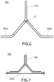
- Figure 6 shows a Y-shaped stringer according to the present invention wherein the rowing (D) is shown.
- the rowing (D) is positioned in between the different plies, that will allow to avoid possible voids in the joint of the different plies.
- the rowing (D) has the function of filling a gap that can remain when joining parts of the stringer, ensuring that the stringer comprises fiber continuity without excess resin in a central area of the stringer to avoid the risk of breakage of the stringer in that central area.
- Figure 7 shows the Y-shaped stringer (100) according to the present invention used as a stiffener for a panel (1010) of an aircraft by joining the first and second flanges (130a, 130b) of the Y-shaped stringer (100) to the composite panel (1010) of the aircraft as shown in figure 7 .
- the panel (1010) can be a composite panel.
- the joining of the first and second flanges (130a, 130b) of the Y-shaped stringer (100) to the panel (1010) of the aircraft can comprise in a first alternative cocuring or in a second alternative cobounding.
- mouseholes (160) are holes made in the ribs of the structure of the aircraft to help positioning and assembling the wing's structure or systems. These holes also permit the interconnection of fuel tanks or other aircraft systems
Landscapes
- Engineering & Computer Science (AREA)
- Mechanical Engineering (AREA)
- Aviation & Aerospace Engineering (AREA)
- Moulding By Coating Moulds (AREA)
Priority Applications (1)
| Application Number | Priority Date | Filing Date | Title |
|---|---|---|---|
| EP23383134.6A EP4552971A1 (fr) | 2023-11-07 | 2023-11-07 | Lisses en y en matériau composite |
Applications Claiming Priority (1)
| Application Number | Priority Date | Filing Date | Title |
|---|---|---|---|
| EP23383134.6A EP4552971A1 (fr) | 2023-11-07 | 2023-11-07 | Lisses en y en matériau composite |
Publications (1)
| Publication Number | Publication Date |
|---|---|
| EP4552971A1 true EP4552971A1 (fr) | 2025-05-14 |
Family
ID=88793122
Family Applications (1)
| Application Number | Title | Priority Date | Filing Date |
|---|---|---|---|
| EP23383134.6A Withdrawn EP4552971A1 (fr) | 2023-11-07 | 2023-11-07 | Lisses en y en matériau composite |
Country Status (1)
| Country | Link |
|---|---|
| EP (1) | EP4552971A1 (fr) |
Citations (5)
| Publication number | Priority date | Publication date | Assignee | Title |
|---|---|---|---|---|
| CA2619767A1 (fr) | 2005-08-19 | 2007-03-01 | Airbus Espana, S.L. | Lisses composites comprenant un bulbe |
| US8540833B2 (en) * | 2008-05-16 | 2013-09-24 | The Boeing Company | Reinforced stiffeners and method for making the same |
| EP2889127B1 (fr) * | 2013-12-27 | 2020-02-05 | Airbus Operations S.L. | Procédé de fabrication d'un élément raidisseur |
| CN210453847U (zh) * | 2019-06-28 | 2020-05-05 | 中国商用飞机有限责任公司 | 复合材料工字型长桁成型用软模垫及复合材料工字型长桁成型模具 |
| US20200353708A1 (en) * | 2019-05-09 | 2020-11-12 | The Boeing Company | Composite Stringer and Methods for Forming a Composite Stringer |
-
2023
- 2023-11-07 EP EP23383134.6A patent/EP4552971A1/fr not_active Withdrawn
Patent Citations (5)
| Publication number | Priority date | Publication date | Assignee | Title |
|---|---|---|---|---|
| CA2619767A1 (fr) | 2005-08-19 | 2007-03-01 | Airbus Espana, S.L. | Lisses composites comprenant un bulbe |
| US8540833B2 (en) * | 2008-05-16 | 2013-09-24 | The Boeing Company | Reinforced stiffeners and method for making the same |
| EP2889127B1 (fr) * | 2013-12-27 | 2020-02-05 | Airbus Operations S.L. | Procédé de fabrication d'un élément raidisseur |
| US20200353708A1 (en) * | 2019-05-09 | 2020-11-12 | The Boeing Company | Composite Stringer and Methods for Forming a Composite Stringer |
| CN210453847U (zh) * | 2019-06-28 | 2020-05-05 | 中国商用飞机有限责任公司 | 复合材料工字型长桁成型用软模垫及复合材料工字型长桁成型模具 |
Similar Documents
| Publication | Publication Date | Title |
|---|---|---|
| EP2703283B1 (fr) | Aile d'avion composite collée | |
| US6190484B1 (en) | Monolithic composite wing manufacturing process | |
| EP2109713B1 (fr) | Aube d'éolienne | |
| EP3945018B1 (fr) | Ensemble d'aile doté de joints d'aile reliant les structures d'aile extérieures à la structure d'aile centrale | |
| EP3138769B1 (fr) | Élément de remplissage contenant des empilements de plis verticaux et plis minces | |
| US10155581B2 (en) | Bonded and tailorable composite assembly | |
| US8771575B2 (en) | Methods and systems for forming reinforced composite articles having variable thickness corners | |
| EP2301840A2 (fr) | Structure d'aeronef integré de matériau composite | |
| US20120087801A1 (en) | Composite components and processes therefor | |
| EP2128018A1 (fr) | Couple de fuselage de charge d'aéronef réalisé à partir d'un matériau composite | |
| US10232926B2 (en) | Integrated lamination process for manufacturing a shell element | |
| US20160375632A1 (en) | Stiffening element and reinforced structure | |
| US12429024B2 (en) | Wind turbine blade shear web | |
| EP4552971A1 (fr) | Lisses en y en matériau composite | |
| US12515429B2 (en) | Manufacture of wind turbine blades | |
| EP4552816A1 (fr) | Procédé de fabrication de lisses en forme de y et lisses en forme de y double en matériau composite | |
| EP4552972A1 (fr) | Longeron en forme de double y en matériau composite | |
| US11623733B2 (en) | Bead-stiffened movable surfaces | |
| CN118597403B (zh) | 一种机翼结构及制备方法 | |
| ASHIZAWA | A 4-flap design with graphite and boron composites | |
| CN121757410A (zh) | 一种无人直升机笼式复合材料机身承力框 | |
| Cooper et al. | Development of highly loaded root end attachments for composite material high speed flying surfaces | |
| JP2014015085A (ja) | 翼用リブ |
Legal Events
| Date | Code | Title | Description |
|---|---|---|---|
| PUAI | Public reference made under article 153(3) epc to a published international application that has entered the european phase |
Free format text: ORIGINAL CODE: 0009012 |
|
| STAA | Information on the status of an ep patent application or granted ep patent |
Free format text: STATUS: THE APPLICATION HAS BEEN PUBLISHED |
|
| AK | Designated contracting states |
Kind code of ref document: A1 Designated state(s): AL AT BE BG CH CY CZ DE DK EE ES FI FR GB GR HR HU IE IS IT LI LT LU LV MC ME MK MT NL NO PL PT RO RS SE SI SK SM TR |
|
| STAA | Information on the status of an ep patent application or granted ep patent |
Free format text: STATUS: THE APPLICATION IS DEEMED TO BE WITHDRAWN |
|
| 18D | Application deemed to be withdrawn |
Effective date: 20251115 |