EP4552985A1 - Appareil de conditionnement de gaz stérile et machine d'emballage pour former des emballages remplis d'un produit versable ayant un appareil de conditionnement de gaz stérile - Google Patents
Appareil de conditionnement de gaz stérile et machine d'emballage pour former des emballages remplis d'un produit versable ayant un appareil de conditionnement de gaz stérile Download PDFInfo
- Publication number
- EP4552985A1 EP4552985A1 EP24210021.2A EP24210021A EP4552985A1 EP 4552985 A1 EP4552985 A1 EP 4552985A1 EP 24210021 A EP24210021 A EP 24210021A EP 4552985 A1 EP4552985 A1 EP 4552985A1
- Authority
- EP
- European Patent Office
- Prior art keywords
- conditioning apparatus
- sterile gas
- gas conditioning
- liquid phase
- inner environment
- Prior art date
- Legal status (The legal status is an assumption and is not a legal conclusion. Google has not performed a legal analysis and makes no representation as to the accuracy of the status listed.)
- Pending
Links
Images

Classifications
-
- B—PERFORMING OPERATIONS; TRANSPORTING
- B65—CONVEYING; PACKING; STORING; HANDLING THIN OR FILAMENTARY MATERIAL
- B65B—MACHINES, APPARATUS OR DEVICES FOR, OR METHODS OF, PACKAGING ARTICLES OR MATERIALS; UNPACKING
- B65B55/00—Preserving, protecting or purifying packages or package contents in association with packaging
- B65B55/02—Sterilising, e.g. of complete packages
- B65B55/027—Packaging in aseptic chambers
-
- A—HUMAN NECESSITIES
- A61—MEDICAL OR VETERINARY SCIENCE; HYGIENE
- A61L—METHODS OR APPARATUS FOR STERILISING MATERIALS OR OBJECTS IN GENERAL; DISINFECTION, STERILISATION OR DEODORISATION OF AIR; CHEMICAL ASPECTS OF BANDAGES, DRESSINGS, ABSORBENT PADS OR SURGICAL ARTICLES; MATERIALS FOR BANDAGES, DRESSINGS, ABSORBENT PADS OR SURGICAL ARTICLES
- A61L2/00—Disinfection or sterilisation of materials or objects, in general; Accessories therefor
- A61L2/16—Disinfection or sterilisation of materials or objects, in general; Accessories therefor using chemical substances
- A61L2/20—Gaseous substances, e.g. vapours
- A61L2/208—Hydrogen peroxide
-
- B—PERFORMING OPERATIONS; TRANSPORTING
- B65—CONVEYING; PACKING; STORING; HANDLING THIN OR FILAMENTARY MATERIAL
- B65B—MACHINES, APPARATUS OR DEVICES FOR, OR METHODS OF, PACKAGING ARTICLES OR MATERIALS; UNPACKING
- B65B55/00—Preserving, protecting or purifying packages or package contents in association with packaging
- B65B55/02—Sterilising, e.g. of complete packages
- B65B55/04—Sterilising wrappers or receptacles prior to, or during, packaging
- B65B55/10—Sterilising wrappers or receptacles prior to, or during, packaging by liquids or gases
- B65B55/103—Sterilising flat or tubular webs
-
- B—PERFORMING OPERATIONS; TRANSPORTING
- B65—CONVEYING; PACKING; STORING; HANDLING THIN OR FILAMENTARY MATERIAL
- B65B—MACHINES, APPARATUS OR DEVICES FOR, OR METHODS OF, PACKAGING ARTICLES OR MATERIALS; UNPACKING
- B65B65/00—Details peculiar to packaging machines and not otherwise provided for; Arrangements of such details
Definitions
- the present invention relates to a sterile gas conditioning apparatus for a packaging machine for forming packages of a pourable product, preferentially a pourable food product.
- the present invention also relates to a packaging machine for forming packages filled with a pourable product, preferentially a pourable food product, having a sterile gas conditioning apparatus.
- liquid or pourable food products such as fruit juice, UHT (ultra-high-temperature treated) milk, wine, tomato sauce, etc.
- UHT ultra-high-temperature treated milk
- wine tomato sauce
- etc. are sold in packages made of sterilized packaging material.
- a typical example is the parallelepiped-shaped package for liquid or pourable food products known as Tetra Brik Aseptic (registered trademark), which is made by sealing and folding laminated strip packaging material.
- the packaging material has a multilayer structure comprising a base layer, e.g. of paper, covered on both sides with layers of heat-seal plastic material, e.g. polyethylene.
- the packaging material also comprises a layer of oxygen-barrier material (an oxygen-barrier layer), e.g. an aluminum foil, which is superimposed on a layer of heat-seal plastic material, and is in turn covered with another layer of heat-seal plastic material forming the inner face of the package eventually contacting the food product.
- Packages of this sort are normally produced on fully automatic packaging machines, which advance a web of packaging material through a sterilization apparatus for sterilizing the web of packaging material at a sterilization station and to an isolation chamber (having a sterile inner environment) in which the sterilized web of packaging material is maintained and advanced.
- the web of packaging material is folded and sealed longitudinally at a tube forming station to form a tube having a longitudinal seam portion, the tube being further fed along a vertical advancing direction.
- the tube is filled with a pourable product, in particular a pourable food product, and is transversally sealed and subsequently cut along equally spaced transversal cross sections within a package forming apparatus of the packaging machine during advancement along the vertical advancing direction.
- a pourable product in particular a pourable food product
- Pillow packages are so obtained, each pillow package having a longitudinal sealing band, a top transversal sealing band and a bottom transversal sealing band.
- a typical packaging machine comprises a conveying device for advancing the web of packaging material along a web advancement path and the tube formed from the web of packaging material along a tube advancement path, the sterilization apparatus for sterilizing the web of packaging material prior to its formation into the tube, a tube forming and sealing device at least partially arranged within the isolation chamber and being configured to form the tube from the advancing web of packaging material and to longitudinally seal the tube, a filling device for filling the tube with the pourable product and the package forming apparatus adapted to form, transversally seal and cut individual packages from the tube of packaging material.
- a typical packaging machine also comprises a sterile gas conditioning apparatus for providing a sterile gas, in particular sterile air, into the inner environment.
- the sterile gas conditioning apparatus defines together with the inner environment and possibly with an inner space of the sterilization apparatus a closed circuit. Thereby, a flow of the sterile gas is guaranteed from the inner environment into the inner space then into the sterile gas conditioning apparatus and back into the inner environment.
- sterile gas conditioning apparatus is configured to guarantee the needed sterility of the sterile gas.
- the sterile gas conditioning apparatus comprises an inlet opening for receiving the air, a cleaning device for removing particles and/or chemical compounds from the air, an aspiration device for generating the aspiration force, a separator for separating a liquid phase from the air and having a draining outlet for the liquid phase and a sterilization device for sterilizing the air.
- the aspiration device receives, in use, water so as to generate a liquid ring seal.
- a sterile gas conditioning apparatus as claimed in claim 1.
- Number 1 indicates as a whole a packaging machine for producing packages, preferentially sealed packages, of a pourable food product, in particular a pourable food product, such as milk, milk drinks, yoghurt, yoghurt drinks, fruit juice, wine, tomato sauce, emulsions, beverages containing pulp, salt, sugar, etc.
- a pourable food product such as milk, milk drinks, yoghurt, yoghurt drinks, fruit juice, wine, tomato sauce, emulsions, beverages containing pulp, salt, sugar, etc.
- Packaging machine 1 may be configured to form packages from a tube 2 obtained from a web 3 of packaging material.
- tube 2 Preferentially, in use, tube 2 extends along a longitudinal axis, more preferentially having a vertical orientation.
- the packaging material forming web 3 may have a multilayer structure, preferentially having heat-seal properties (i.e. portions of the multilayer packaging material can be sealed to one another).
- the multilayer packaging material may comprise at least one layer of fibrous material, such as e.g. paper or cardboard, and at least two layers of heat-seal plastic material, e.g. polyethylene, interposing the layer of fibrous material in between one another.
- the multilayer packaging material may comprise at least one layer of fibrous material, such as e.g. paper or cardboard, and at least two layers of heat-seal plastic material, e.g. polyethylene, interposing the layer of fibrous material in between one another.
- one of these two layers of heat-seal plastic material may define the inner face of the packages contacting the pourable product.
- the multilayer packaging material may also comprise a layer of gas- and light-barrier material, e.g. aluminum foil or ethylene vinyl alcohol (EVOH) film, preferentially being arranged between one of the layers of heat-seal plastic material and the layer of fibrous material.
- gas- and light-barrier material e.g. aluminum foil or ethylene vinyl alcohol (EVOH) film
- the packaging material may also comprise a further layer of heat-seal plastic material being interposed between the layer of gas- and light-barrier material and the layer of fibrous material.
- packaging machine 1 may comprise an isolation chamber 4 having an inner environment 5, e.g. containing a sterile gas, more specifically sterile air.
- isolation chamber 4 divides inner environment 5 from an outer environment 6.
- isolation chamber 4 allows to package the pourable product under sterile (aseptic) conditions.
- packaging machine 1 may comprise a sterilization apparatus 7 (only partially shown) for sterilizing the packaging material, more specifically web 3. More specifically, sterilization apparatus 7 may be configured to sterilize the packaging material, more specifically web 3.
- sterilization apparatus 7 may comprise an inner space 8 within which, in use, the packaging material, more specifically web 3, is sterilized.
- sterilization apparatus 7 may comprise a sterilization unit arranged within inner space 8 configured to sterilize the packaging material.
- the sterilization unit may be configured to sterilize the packaging material by chemical sterilization such as by means of hydrogen peroxide.
- the sterilization unit may be configured to sterilize the packaging material by means of physical sterilization such as electron beam sterilization.
- inner space 8 and inner environment 5 may be in fluid connection with one another.
- the packaging material, more specifically web 3 may enter inner environment 5 through and from inner space 8 (in other words, the packaging material, more specifically web 3, is at first sterilized and then introduced into inner environment 5).
- packaging machine 1 may comprise a conveying device configured to advance web 3 along a web advancement path, more specifically from a delivery station to a tube forming station, at which, in use, web 3 is formed into tube 2.
- the conveying device may also be configured to advance tube 2 along a tube advancement path Q.
- Packaging machine 1 may comprise a tube forming and sealing device at least partially arranged within inner environment 5 and being configured to form tube 2, more specifically to fold tube 2 from web 3, and to longitudinally seal tube 2.
- the tube forming and sealing device is preferentially arranged at tube forming station.
- the tube forming and sealing device may be at least partially arranged within isolation chamber 4, more specifically inner environment 5, and may be configured to form and longitudinally seal tube 2 within isolation chamber 4, more specifically inner environment 5.
- the tube forming and sealing device may be configured to gradually fold web 3 into tube 2 by overlapping a first lateral edge of web 3 and a second lateral edge of web 3 with one another for forming a longitudinal seam portion of tube 2.
- the tube forming and sealing device may be configured to longitudinally seal the longitudinal seam portion.
- the conveying device may be configured to advance tube 2 and any intermediate of tube 2 along tube advancement path Q.
- any configuration of web 3 is meant prior to obtaining the tube structure and after folding of web 3 by the tube forming and sealing device has started.
- the intermediates of tube 2 are a result of the gradual folding of web 3 so as to obtain tube 2, preferentially by overlapping with one another the first lateral edge of web 3 and the second lateral edge of web 3.
- packaging machine 1 may comprise a filling device 13 configured to fill tube 2 with the pourable product.
- filling device 13 may comprise a filling pipe 14 being and/or being configured to be put in fluid connection with a pourable product storage tank, which is adapted to store/provide for the pourable product to be packaged.
- filling pipe 14 may be configured to direct, in use, the pourable product into tube 2.
- filling pipe 14 may be configured to be, in use, at least partially placed within tube 2 for feeding the pourable product into tube 2.
- Packaging machine 1 may also comprise a package forming apparatus 15 configured to manipulate, more specifically to at least partially shape and/or transversally seal and/or transversally cut, tube 2 for obtaining the packages from tube 2.
- package forming apparatus 15 may be arranged downstream of isolation chamber 4 along tube advancement path Q.
- package forming apparatus 15 may comprise a plurality of operative assemblies 16 (only one being partially shown) and a plurality of counter-operative assemblies 17 (only one being partially shown) configured to manipulate in collaboration with one another tube 2 for forming the packages, more specifically to at least partially shape and/or transversally seal and/or transversally cut, tube 2 for forming the packages.
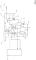
- packaging machine 1 also comprises a sterile gas conditioning apparatus 20 configured to condition a gas, more specifically air, to be used in packaging machine 1, more specifically to be introduced into inner environment 5.
- a gas more specifically air
- sterile gas conditioning apparatus 20 may be configured to treat the gas so as to obtain a sterile gas (which can be introduced into inner environment 5 and which corresponds to defined hygienic standards, i.e. fulfils defined hygienic requirements).
- sterile gas conditioning apparatus 20 may be configured to produce a sterile gas, more specifically sterile air, to be used within packaging machine 1, more specifically to be introduced into inner environment 5.
- At least portions of sterile gas conditioning apparatus 20 may define a closed gas flow circuit together with portions of packaging machine 1, more specifically together with inner environment 5 and inner space 8.
- the gas conditioned by sterile conditioning apparatus 20 may be injected into inner environment 5 at one or more injection stations.
- packaging machine 1 may comprise a control unit configured to control that a first pressure within inner environment 5 may be greater than ambient pressure and greater than a second pressure within inner space 8. Additionally, the second pressure may be greater than ambient pressure too.
- sterile gas conditioning apparatus 20 comprises:
- cleaning device 24, aspiration device 25 and separation device 26 may be integrated into flow circuit 21.
- cleaning device 24, aspiration device 25 and separation device 26 may be fluidically interposed between inlet opening 22 and outlet opening 23.
- cleaning device 24 may be arranged downstream of inlet opening 22, aspiration device 25 may be arranged downstream of cleaning device 24, each separation device 26 may be arranged downstream of aspiration device 25 and outlet opening 23 may be arranged downstream of each separation device 26.
- cleaning device 24 may be fluidically interposed between inlet opening 22 and aspiration device 25.
- aspiration device 25 may be fluidically interposed between cleaning device 24 and the one or more separation devices 26.
- the one or more separation devices 26 may be fluidically interposed between aspiration device 25 and outlet opening 23.
- each separation device 26 may comprise a collection portion 27 for collecting the liquid phase and an outlet aperture configured to allow for the outflow of at least a portion of the liquid phase being, in use, collected within the respective collection portion 27.
- sterile gas conditioning apparatus 20 e.g. flow circuit 21, may comprise an injection unit 29 configured to inject a liquid, e.g. water, into cleaning device 24.
- a liquid e.g. water
- separation device 26 may allow to at least partially reduce the liquid phase of the gas resulting from the operation of injection unit 29.
- sterile gas conditioning apparatus 20 also comprises one or more tubing arrangements 30, each tubing arrangement 30 fluidically connecting one respective outlet aperture of each separation device 26 with a respective intake opening 31 of the flow circuit 21 creating a respective closed recycle circuit 32 between at least a portion of flow circuit 21 and the respective collecting portion 27.
- each intake opening 31 is configured to allow for the introduction of the liquid phases into flow circuit 21.
- sterile gas conditioning apparatus 20 may comprise two separation devices 26, in the specific case giving rise to two closed recycle circuits 32.
- separation devices 26 may be arranged fluidically in series (with respect to the flow of the gas). In other words, separation devices 26 may be arranged one after the other along flow circuit 21, i.e. one separation device 26 is arranged upstream of the other separation device 26 along flow circuit 21.
- one intake opening 31 may be fluidically interposed between cleaning device 24 and aspiration device 25 (i.e. the liquid phase may enter the flow circuit 21 at a position being interposed between cleaning device 24 and aspiration device 25) and/or intake opening 31 may be associated to aspiration device 25.
- the liquid phase is transferred from one respective collecting portion 27 to aspiration device 25.
- aspiration device 25 may be configured to use the liquid phase for generating, in use, a liquid ring seal.
- aspiration device 25 may consist of and/or may comprise a liquid ring compressor and at least a portion of the liquid phase (the water collected in collection portion 27) is used to generate a liquid ring seal of the liquid ring compressor. In other words, at least a portion of the liquid phase (the water collected in collection portion 27) is returned to aspiration device 25 for obtaining the desired liquid ring seal.
- one intake opening 31 may be fluidically interposed between inlet opening 22 and cleaning device 24 and/or intake opening 31 may be associated to cleaning device 24.
- the liquid phase is transferred from one respective collecting portion 27 to cleaning device 24.
- flow circuit 21 may comprise more than one intake opening 31.
- at least a portion of the liquid phase collected in one respective collection portion 27 is transferred to cleaning device 24 and at least a portion of the liquid phase collected in another respective collection portion 27 is transferred to aspiration device 25.
- at least a portion of the liquid phase collected in the collection portion 27 of the separation device 26 that is arranged upstream of the other separation device 26 along flow circuit 21 is transferred to aspiration device 25.
- at least a portion of the liquid phase collected in the collection portion 27 of the separation device 26 that is arranged downstream of the other separation device 26 along flow circuit 21 is transferred to cleaning device 24.
- each intake opening 31 may be fluidically connected to more than one collection portion 27.
- one intake opening 31 may be used to deliver at least a portion of the liquid phase to injection unit 29.
- At least one separation device 26 may comprise an auxiliary aperture 28 configured to allow to drain a portion of the liquid phase present within collection portion 27.
- auxiliary aperture 28 configured to allow to drain a portion of the liquid phase present within collection portion 27.
- each separation device 26 having an auxiliary aperture 28 may be configured to hold a desired level of the liquid phase, and advantageously, may comprise a control valve associated to the respective auxiliary aperture 28 configured to keep the desired level of the liquid phase.
- sterile gas conditioning apparatus 20 may further comprise one or more main heat exchangers 33, each having at least a first pipe 34 for the gas and a second pipe 35 for a fluid, more specifically for a liquid.
- first pipes 34 may be part of flow circuit 21 and may be fluidically interposed between inlet opening 22 and outlet opening 23.
- main heat exchangers 33 may be arranged fluidically in series.
- each main heat exchanger 33 may be arranged fluidically downstream of at least one respective separation device 26.
- one main heat exchanger 33 may be fluidically interposed between two separation devices 26.
- sterile gas conditioning unit 20 may comprise two main heat exchangers 33.
- a first separation device 26 of the two separation devices 26 is arranged fluidically downstream of cleaning device 24 and aspiration device 25, a first main heat exchanger 33 of the two main heat exchangers 33 is arranged fluidically downstream of the first separation device 26, a second separation device 26 of the two separation devices 66 is arranged fluidically downstream of the first main heat exchanger 33, and a second main heat exchanger 33 of the two main heat exchangers 33 is arranged fluidically downstream of the second separation device 26.
- one main heat exchanger 33 may be configured to cool the sterile gas and/or another main heat exchanger 33 may be configured to heat the sterile gas.
- the main heat exchanger 33 being configured to heat the sterile gas may be arranged downstream of the main heat exchanger 33 being configured to cool the sterile gas.
- the main heat exchanger 33 being configured to cool the sterile gas may be coupled to the respective closed recycle circuit 32.
- the main heat exchanger 33 being configured to heat the sterile gas may be configured to exchange heat between the sterile gas and the liquid phase flowing within closed recycle circuit 32.
- the main heat exchanger 33 (the upstream main heat exchanger 33) being arranged upstream of the other main heat exchanger 33 (the downstream main heat exchanger 33) is designed to recover more liquid phase than the downstream main heat exchanger 33, while the liquid phase recovered by the downstream main heat exchanger 33 has a lower temperature than the liquid phase recovered by the upstream main heat exchanger 33.
- packaging machine 1 may comprise a chilling unit 36.
- chilling unit 36 may be fluidically coupled to one main heat exchanger 33, more specifically to the respective second pipe 35.
- the other main heat exchanger 33 is not fluidically connected to chilling unit 36 and may be fluidically coupled to a respective closed recycle circuit 32.
- respective first pipe 34 of the main heat exchanger 33 being fluidically coupled to the respective closed recycle circuit 32 may be arranged fluidically downstream of the respective first pipe 34 of the main heat exchanger being 33 fluidically coupled to chilling unit 36.
- the main heat exchanger 33 being configured to cool the sterile gas may be configured to cool the sterile gas by heat exchange with water originating from chilling unit 36 and such water may flow, in use, through the respective second pipe 35.
- sterile gas conditioning unit 20 may comprise at least one auxiliary heat exchanger 37 having a first pipe 38 for the liquid phase and a second pipe 39 for wastewater of chilling unit 36.
- auxiliary heat exchanger 37 may be configured to cool the liquid phase, in particular by heat exchange between the liquid phase and the wastewater of chilling unit 36.
- second pipe 39 may be integrated into a respective closed recycle circuit 32.
- At least one main heat exchanger 33 and auxiliary heat exchanger 37 may be arranged such that respectively second pipe 35 and second pipe 39 are comprised by a respective closed recycle circuit 32.
- first pipe 38 may be fluidically coupled to chilling unit 36.
- second pipe 39 may be arranged fluidically downstream of the respective second pipe 35 which is integrated into closed recycle circuit 32.
- one separation device 26 may be arranged fluidically upstream (with respect to the flow of the gas) of main heat exchangers 33.
- one separation device 26 may be fluidically interposed (with respect to the flow of the gas) between two main heat exchangers 33, more specifically between the respective first pipes 34.
- At least one of closed recycle circuits 32 may comprise a pumping device 41 configured to generate a pumping force for controlling flow of the respective liquid phase through the respective closed recycle circuit 32.
- sterile gas conditioning apparatus 20 may further comprise a sterilization device 42 being configured to sterilize the gas prior to exiting through outlet opening 23.
- sterilization device 42 may be fluidically interposed between outlet opening 23 and the one or more separation devices 26.
- packaging machine 1 forms packages filled with the pourable product.
- Packaging machine 1 forms the packages from tube 2 being formed from the web of packaging material 3 within inner environment 5.
- the conveying device advances web of packaging material 3 along the advancement path and within inner environment 5 within which web of packaging material 3 is formed by the tube forming and sealing device. Additionally, tube 2 is filled by filling device 13 with the pourable product.
- the conveying device also advances tube 3 along tube advancement path Q.
- Package forming apparatus 15 forms and transversally seals tube 3 and, preferentially, also transversally cuts tube 3 so as to obtain the packages.
- sterile gas conditioning apparatus 20 sterilizes the gas exiting from inner environment 5 and feeds it after its conditioning back into inner environment 5.
- Cleaning device 24 removes particles and/or chemical compounds from the gas
- aspiration device 25 generates the aspiration force for directing at least the gas through inlet opening 22 and into flow circuit 21 and each separation device 26 separates the liquid phase from the gas.
- each liquid phase collected in the respective collection portion 27 is at least partially fed through the respective intake opening 31 into flow circuit 21.
- the gas is fed through one or more main heat exchangers 33.
- sterilizing device 42 sterilizes the gas prior to its reintroduction into inner environment 5.
- packaging machine 1 According to the present invention will be clear from the foregoing description.
- main heat exchangers 33 and/or auxiliary heat exchanger 37 allows to optimize the energy consumption.
- a pre-heating of the sterile gas can be obtained thanks to the respective main heat exchanger 33 being configured to heat the sterile gas prior to the sterile gas entering sterilization device 42.
- the portion of liquid phase recovered from the main heat exchanger 33 arranged downstream of the heat exchanger 33 being configured to cool the sterile gas it is possible to keep the recycled liquid phase below a threshold temperature.
Landscapes
- Mechanical Engineering (AREA)
- Engineering & Computer Science (AREA)
- Health & Medical Sciences (AREA)
- Animal Behavior & Ethology (AREA)
- Epidemiology (AREA)
- Life Sciences & Earth Sciences (AREA)
- Chemical & Material Sciences (AREA)
- General Health & Medical Sciences (AREA)
- Public Health (AREA)
- Veterinary Medicine (AREA)
- General Chemical & Material Sciences (AREA)
- Chemical Kinetics & Catalysis (AREA)
- Apparatus For Disinfection Or Sterilisation (AREA)
- Filling Of Jars Or Cans And Processes For Cleaning And Sealing Jars (AREA)
Applications Claiming Priority (1)
| Application Number | Priority Date | Filing Date | Title |
|---|---|---|---|
| IT102023000023268A IT202300023268A1 (it) | 2023-11-06 | 2023-11-06 | Apparato di condizionamento di un gas sterile e macchina di confezionamento per formare pacchetti riempiti con un prodotto versabile avente un apparato di condizionamento di un gas sterile |
Publications (1)
| Publication Number | Publication Date |
|---|---|
| EP4552985A1 true EP4552985A1 (fr) | 2025-05-14 |
Family
ID=89474421
Family Applications (1)
| Application Number | Title | Priority Date | Filing Date |
|---|---|---|---|
| EP24210021.2A Pending EP4552985A1 (fr) | 2023-11-06 | 2024-10-31 | Appareil de conditionnement de gaz stérile et machine d'emballage pour former des emballages remplis d'un produit versable ayant un appareil de conditionnement de gaz stérile |
Country Status (3)
| Country | Link |
|---|---|
| EP (1) | EP4552985A1 (fr) |
| IT (1) | IT202300023268A1 (fr) |
| WO (1) | WO2025098865A1 (fr) |
Citations (2)
| Publication number | Priority date | Publication date | Assignee | Title |
|---|---|---|---|---|
| CN102311922A (zh) * | 2010-07-07 | 2012-01-11 | 中国石油化工股份有限公司 | 一种微藻高效培养的方法 |
| US20220031888A1 (en) * | 2018-12-10 | 2022-02-03 | Gustavo BERMUDEZ GUERRERO | System for preventing scaling, removing hydrogen peroxide residues and recycling water in aseptic filling systems of laminated carton containers |
-
2023
- 2023-11-06 IT IT102023000023268A patent/IT202300023268A1/it unknown
-
2024
- 2024-10-31 WO PCT/EP2024/080791 patent/WO2025098865A1/fr active Pending
- 2024-10-31 EP EP24210021.2A patent/EP4552985A1/fr active Pending
Patent Citations (2)
| Publication number | Priority date | Publication date | Assignee | Title |
|---|---|---|---|---|
| CN102311922A (zh) * | 2010-07-07 | 2012-01-11 | 中国石油化工股份有限公司 | 一种微藻高效培养的方法 |
| US20220031888A1 (en) * | 2018-12-10 | 2022-02-03 | Gustavo BERMUDEZ GUERRERO | System for preventing scaling, removing hydrogen peroxide residues and recycling water in aseptic filling systems of laminated carton containers |
Also Published As
| Publication number | Publication date |
|---|---|
| WO2025098865A1 (fr) | 2025-05-15 |
| IT202300023268A1 (it) | 2025-05-06 |
Similar Documents
| Publication | Publication Date | Title |
|---|---|---|
| EP3549878B1 (fr) | Machine d'emballage et procédé pour produire des emballages scellés | |
| EP3656686B1 (fr) | Appareil d'emballage pour former des emballages scellés | |
| EP3623301B1 (fr) | Appareil d'emballage pour former des emballages scellés | |
| EP3656687B1 (fr) | Procédé et appareil d'emballage pour former des emballages scellés | |
| EP3549613B1 (fr) | Appareil de stérilisation, machine d'emballage comportant un appareil de stérilisation et procédé de stérilisation | |
| EP3656688B1 (fr) | Procédé et appareil d'emballage pour former des emballages scellés partiellement remplis | |
| EP4032819B1 (fr) | Convoyeur d'alimentation pour un appareil de pliage, appareil de pliage doté d'un convoyeur d'alimentation et machine d'emballage comportant un appareil de pliage | |
| EP3708506A1 (fr) | Machine d'emballage pour produire des emballages scellés | |
| EP4552985A1 (fr) | Appareil de conditionnement de gaz stérile et machine d'emballage pour former des emballages remplis d'un produit versable ayant un appareil de conditionnement de gaz stérile | |
| EP3699104A1 (fr) | Procédé et machine d'emballage pour la production d'emballages scellés | |
| EP4563480A1 (fr) | Machine d'emballage et procédé de nettoyage d'une machine d'emballage | |
| EP4467470A1 (fr) | Machine d'emballage pour former des emballages remplis d'un produit versable et ligne d'emballage comportant une machine d'emballage | |
| EP4606713A1 (fr) | Machine d'emballage et procédé de stérilisation d'une machine d'emballage | |
| EP4549329A1 (fr) | Appareil de formation d'emballages pour une machine d'emballage et machine d'emballage pour former des emballages remplis d'un produit versable | |
| CN120752181A (zh) | 用于形成多个用可倾倒产品填充的密封包装的包装装置 | |
| CN121469950A (zh) | 用于包装机的套件和用于形成填充有可倾倒产品的包装的包装机 | |
| CN121079251A (zh) | 用于形成多个用可倾倒产品填充的密封包装的包装装置和方法 |
Legal Events
| Date | Code | Title | Description |
|---|---|---|---|
| PUAI | Public reference made under article 153(3) epc to a published international application that has entered the european phase |
Free format text: ORIGINAL CODE: 0009012 |
|
| STAA | Information on the status of an ep patent application or granted ep patent |
Free format text: STATUS: THE APPLICATION HAS BEEN PUBLISHED |
|
| AK | Designated contracting states |
Kind code of ref document: A1 Designated state(s): AL AT BE BG CH CY CZ DE DK EE ES FI FR GB GR HR HU IE IS IT LI LT LU LV MC ME MK MT NL NO PL PT RO RS SE SI SK SM TR |
|
| STAA | Information on the status of an ep patent application or granted ep patent |
Free format text: STATUS: REQUEST FOR EXAMINATION WAS MADE |
|
| 17P | Request for examination filed |
Effective date: 20251114 |