EP4552995A2 - Rubber plug - Google Patents
Rubber plug Download PDFInfo
- Publication number
- EP4552995A2 EP4552995A2 EP25167450.3A EP25167450A EP4552995A2 EP 4552995 A2 EP4552995 A2 EP 4552995A2 EP 25167450 A EP25167450 A EP 25167450A EP 4552995 A2 EP4552995 A2 EP 4552995A2
- Authority
- EP
- European Patent Office
- Prior art keywords
- leg portion
- rubber stopper
- canopy
- leg
- needle
- Prior art date
- Legal status (The legal status is an assumption and is not a legal conclusion. Google has not performed a legal analysis and makes no representation as to the accuracy of the status listed.)
- Pending
Links
Images


Classifications
-
- B—PERFORMING OPERATIONS; TRANSPORTING
- B65—CONVEYING; PACKING; STORING; HANDLING THIN OR FILAMENTARY MATERIAL
- B65D—CONTAINERS FOR STORAGE OR TRANSPORT OF ARTICLES OR MATERIALS, e.g. BAGS, BARRELS, BOTTLES, BOXES, CANS, CARTONS, CRATES, DRUMS, JARS, TANKS, HOPPERS, FORWARDING CONTAINERS; ACCESSORIES, CLOSURES, OR FITTINGS THEREFOR; PACKAGING ELEMENTS; PACKAGES
- B65D39/00—Closures arranged within necks or pouring openings or in discharge apertures, e.g. stoppers
- B65D39/0005—Closures arranged within necks or pouring openings or in discharge apertures, e.g. stoppers made in one piece
- B65D39/0023—Plastic cap-shaped hollow plugs
-
- A—HUMAN NECESSITIES
- A61—MEDICAL OR VETERINARY SCIENCE; HYGIENE
- A61J—CONTAINERS SPECIALLY ADAPTED FOR MEDICAL OR PHARMACEUTICAL PURPOSES; DEVICES OR METHODS SPECIALLY ADAPTED FOR BRINGING PHARMACEUTICAL PRODUCTS INTO PARTICULAR PHYSICAL OR ADMINISTERING FORMS; DEVICES FOR ADMINISTERING FOOD OR MEDICINES ORALLY; BABY COMFORTERS; DEVICES FOR RECEIVING SPITTLE
- A61J1/00—Containers specially adapted for medical or pharmaceutical purposes
- A61J1/05—Containers specially adapted for medical or pharmaceutical purposes for collecting, storing or administering blood, plasma or medical fluids ; Infusion or perfusion containers
- A61J1/06—Ampoules or carpules
- A61J1/065—Rigid ampoules, e.g. glass ampoules
-
- A—HUMAN NECESSITIES
- A61—MEDICAL OR VETERINARY SCIENCE; HYGIENE
- A61J—CONTAINERS SPECIALLY ADAPTED FOR MEDICAL OR PHARMACEUTICAL PURPOSES; DEVICES OR METHODS SPECIALLY ADAPTED FOR BRINGING PHARMACEUTICAL PRODUCTS INTO PARTICULAR PHYSICAL OR ADMINISTERING FORMS; DEVICES FOR ADMINISTERING FOOD OR MEDICINES ORALLY; BABY COMFORTERS; DEVICES FOR RECEIVING SPITTLE
- A61J1/00—Containers specially adapted for medical or pharmaceutical purposes
- A61J1/14—Details; Accessories therefor
- A61J1/1406—Septums, pierceable membranes
-
- A—HUMAN NECESSITIES
- A61—MEDICAL OR VETERINARY SCIENCE; HYGIENE
- A61J—CONTAINERS SPECIALLY ADAPTED FOR MEDICAL OR PHARMACEUTICAL PURPOSES; DEVICES OR METHODS SPECIALLY ADAPTED FOR BRINGING PHARMACEUTICAL PRODUCTS INTO PARTICULAR PHYSICAL OR ADMINISTERING FORMS; DEVICES FOR ADMINISTERING FOOD OR MEDICINES ORALLY; BABY COMFORTERS; DEVICES FOR RECEIVING SPITTLE
- A61J1/00—Containers specially adapted for medical or pharmaceutical purposes
- A61J1/14—Details; Accessories therefor
- A61J1/1412—Containers with closing means, e.g. caps
- A61J1/1425—Snap-fit type
-
- B—PERFORMING OPERATIONS; TRANSPORTING
- B65—CONVEYING; PACKING; STORING; HANDLING THIN OR FILAMENTARY MATERIAL
- B65D—CONTAINERS FOR STORAGE OR TRANSPORT OF ARTICLES OR MATERIALS, e.g. BAGS, BARRELS, BOTTLES, BOXES, CANS, CARTONS, CRATES, DRUMS, JARS, TANKS, HOPPERS, FORWARDING CONTAINERS; ACCESSORIES, CLOSURES, OR FITTINGS THEREFOR; PACKAGING ELEMENTS; PACKAGES
- B65D51/00—Closures not otherwise provided for
- B65D51/002—Closures to be pierced by an extracting-device for the contents and fixed on the container by separate retaining means
-
- A—HUMAN NECESSITIES
- A61—MEDICAL OR VETERINARY SCIENCE; HYGIENE
- A61J—CONTAINERS SPECIALLY ADAPTED FOR MEDICAL OR PHARMACEUTICAL PURPOSES; DEVICES OR METHODS SPECIALLY ADAPTED FOR BRINGING PHARMACEUTICAL PRODUCTS INTO PARTICULAR PHYSICAL OR ADMINISTERING FORMS; DEVICES FOR ADMINISTERING FOOD OR MEDICINES ORALLY; BABY COMFORTERS; DEVICES FOR RECEIVING SPITTLE
- A61J2200/00—General characteristics or adaptations
- A61J2200/10—Coring prevention means, e.g. for plug or septum piecing members
Definitions
- the present invention relates to a rubber stopper. More specifically, the present invention relates to a rubber stopper capable of preventing occurrence of coring.
- a vial and an ampoule as containers for storing a drug solution.
- the vial is sealed by a rubber stopper capped to a lip of a pharmaceutical container mainly made of glass, plastic, and the like. Sticking a needle into the rubber stopper enables communication with an instrument such as a syringe without opening (or breaking) the container; therefore, work can be hygienically performed so as not to open the container carelessly.
- the rubber stopper that is applied to the lip of the pharmaceutical container.
- the quality characteristics required for the rubber stopper used for sealing or capping a lip of a vial for storing a drug product such as antibiotics should conform to the test for rubber closure for aqueous infusions of Japanese Pharmacopoeia due to its purpose of use.
- Patent Literature 1 discloses a rubber stopper for a vial including a lid portion having an upper surface and a lower surface, and a leg portion provided on the lower surface of the lid portion, in which a needle piercing portion at the center of the lid portion is recessed so that the lower surface of the lid portion is positioned between an upper surface and an lower surface of the needle piercing portion, and a lower surface of the canopy portion has a flat (planar) shape to thereby suppress coring.
- Patent Literature 2 discloses a rubber stopper for a vial including a canopy portion having a flange, a puncturing area formed to have a recessed portion on a top surface of the canopy portion and formed to longitudinally traverse the canopy portion from the recessed portion to a bottom surface, and a leg portion formed on the bottom surface of the canopy portion so as to protrude downward at an outer position of the puncturing area with respect to an axial center of the canopy portion, in which the puncturing area is formed of rubber with a rubber hardness from 20 to 35, and the top surface other than the recessed portion of the canopy portion is formed of rubber with a rubber hardness of 58 to 90 to thereby suppress coring because a plurality of materials are used.
- Patent Literature 3 discloses a vial and a sealing device used for the same, in which a sealing member corresponding to a rubber stopper can be easily switched from a half-capped posture where the interior of a vial housing communicates with outside space to a sealed posture where the communication is cut off, and the sealed posture can be positively maintained after sealing with a simple structure inexpensively.
- a prime objective of the present invention is to solve the problem of occurrence of coring.
- the present invention provides a rubber stopper including a canopy portion having an upper surface and a lower surface, and a leg portion provided on the lower surface of the canopy portion, in which the leg portion has a tapered base portion at the center on a lower surface side of the canopy portion, and a curvature radius R1 of the tapered base portion is 2mm or more and 4mm or less.
- a length P of an inner wall of the leg portion may be longer than a length D of the leg portion itself, which is greater than 100% and less than 160% with respect to the length D of the leg portion itself.
- a distance R2 between a start point and an end point of an arc including an apex of the tapered base portion may be 8 mm or less.
- the canopy portion may have a recessed portion at the center on an upper surface side of the canopy portion, and an outer diameter R3 of the recessed portion may be 90% or less with respect to the distance R2.
- the canopy portion may have a needle sticking portion into which a needle is stuck, and a thickness E of the needle sticking portion may be 60% or more and less than 100% of a thickness C of the canopy portion.
- the thickness E of the needle sticking portion may be 3 mm or less.
- the thickness E of the needle sticking portion may be 15% or more and 40% or less with respect to the length D of the leg portion itself.
- the leg portion may have a cutout at least at one place.
- the leg portion may be provided with a ring-shaped convex portion on an outer peripheral surface on an end side of the leg portion.
- the rubber stopper according to the present invention may be used for sealing a lyophilized drug product.
- a rubber stopper capable of suppressing occurrence of coring can be provided.
- Embodiments described below are examples of a representative embodiment of the present invention, and the scope of the present invention should not be narrowly interpreted based on these examples.
- a rubber stopper 1 includes a canopy portion 11 having an upper surface and a lower surface, and a leg portion 12 provided on the lower surface of the canopy portion 11, in which the leg portion 12 has a tapered base portion 10 with an approximately semispherical shape at the center on a lower surface side of the canopy portion, and a curvature radius R1 of the tapered base portion 10 is 2mm or more and 4mm or less.
- a thickness of the canopy portion and a length of the leg portion are approximately the same, and the length of the leg portion is short; therefore, a shape of the leg portion which can secure stability of the rubber stopper in a half-capped state as in a rubber stopper for a lyophilized drug product is not mentioned though the problem of coring is solved, and there is also a problem that there is a tendency to fall over at the time of being conveyed.
- the rubber stopper is manufactured using a plurality of rubber materials with different hardnesses; therefore, there is a problem that manufacturing costs are high.
- the prevent invention a prime objective of which is to solve the problem of occurrence of coring, provides a rubber stopper having the shape of the leg portion which can secure stability of the rubber stopper in the half-capped state as in the rubber stopper for the lyophilized drug product, suppressing occurrence of coring even when using a single rubber material with the same hardness, reducing the number of components, and suitable for lyophilization with low manufacturing costs.
- the curvature radius R1 is a radius corresponding to an arc including an apex of the tapered base portion 10 as illustrated in FIG. 1 .
- a center point of the curvature radius R1 is on a perpendicular line (central axis) extending from the apex of the tapered base portion 10 toward the center of the leg portion 12, and a start point and an end point of the arc are set as an "R stop portion 1".
- the "R stop portion 1" is part of a length P of an inner wall of the leg portion 12.
- the curvature radius R1 is, more preferably, 2mm or more and 3mm or less.
- the rubber stopper 1 according to the present invention occurrence of coring is suppressed in both cases where a plastic needle is used and where a metallic needle is used as a needle as illustrated in later-described examples.
- the plastic needle is used for a closed system drug transfer device (CSTD); therefore, the rubber stopper 1 according to the present invention can be used also for sealing a drug product for the CSTD.
- CSTD closed system drug transfer device
- the rubber stopper 1 As a material for forming the rubber stopper 1 according to the present invention, for example, synthetic rubbers such as a butyl rubber, an isoprene rubber, a butadiene rubber, a halogenated butyl rubber, ethylenepropylene rubber, and a silicone rubber or natural rubber and so on can be cited.
- the present invention can be also applied to a so-called laminated rubber stopper in which, for example, a film containing fluorine-based resin is laminated on a rubber stopper.
- fluorine-based resin for example, a tetrafluoroethylene resin, a chlorotrifluoroethylene resin, a tetrafluoroethylene-hexafluoropropylene copolymer resin, a vinylidene fluoride resin, a vinyl fluoride resin, a tetrafluoroethylene-ethylene copolymer resin, a chlorotrifluoroethylene-ethylene copolymer resin, and the like can be cited.
- a thickness of the film to be laminated can be, for example, 0.002 mm or more and 0.5 mm or less.
- a hardness of the rubber stopper 1 according to the present invention is, for example, 25 to 45, and preferably 28 to 40.
- a length P of the inner wall of the leg portion 12 (a length from the apex of the tapered base portion 10 to a flattening point (see A of FIG. 1 ) on a ground side of the leg portion 12 (at an inner end of the leg portion 12 in R stop portions 2) is longer than a length D of the leg portion 12 itself (a shortest distance from the lower surface of the canopy portion to a plane to be flat on the ground side of the leg portion 12 (see A of FIG. 1 )), and is preferably greater than 100% and less than 160% with respect to the length D of the leg portion 12 itself, and is more preferably greater than 100% and less than 145%. According to the above, it is possible to prevent that the film is extended too much when laminating the leg portion 12 and to prevent that a molding defect such as damage of the film is caused.
- a distance R2 between the start point and the end point of the arc including the apex of the tapered base portion 10 is preferably 8 mm or less, and more preferably 6 mm or less.
- the distance R2 exceeds 10 mm, moldability is not good, and the film does not easily stick to the leg portion.
- the distance R2 is less than 4 mm, a center needle is likely to scrape the inner wall surface, and coring is likely to occur.
- the distance R2 is a chord length of the arc including the apex of the tapered base portion 10 obtained by extending a horizontal line from the point of the "R stop portion 1" in a radial direction as illustrated in FIG. 1 .
- the positions of the start point and the end point of the "R stop portion 1" can be defined by a position of an outer diameter R3 of a later-described recessed portion 111 or the length D of the leg portion 12 itself to be required. Furthermore, the positions of the start point and the end point of the "R stop portion 1" can be defined as the same height as an outer diameter position of an annular protrusion B provided on a lower surface of the canopy portion as illustrated in FIG. 1 , or within a range of ⁇ 10% of the height of the outer diameter position of the annular protrusion B.
- a curvature radius on the curved line connecting two points of the "R stop portion 2" is preferably 0.1 to 1.0 mm, more preferably, approximately 0.5 mm.
- the canopy portion 11 has the recessed portion 111 at the center on an upper surface side of the canopy portion, and the outer diameter R3 of the recessed portion 111 is preferably 90% or less with respect to the distance R2. According to the above, occurrence of coring can be further suppressed.
- the canopy portion 11 provided with the recessed portion 111 at the center on the upper surface side of the canopy portion includes a needle sticking portion 112 to be a bottom surface of the recessed portion 111, into which a needle is stuck, and a thickness E of the needle sticking portion 112 is preferably 60% or more and less than 100% of a thickness C of the canopy portion.
- a thickness E of the needle sticking portion 112 is preferably 60% or more and less than 100% of a thickness C of the canopy portion.
- the thickness E of the needle sticking portion 112 is preferably 3 mm or less. When the thickness E of the needle sticking portion 112 exceeds 3 mm, the risk of occurrence of coring is increased. Needle sticking resistance generated when sticking the needle is also increased.
- a lower limit value of the thickness E of the needle sticking portion 112 is not particularly limited; however, the lower limit value is preferably 1 mm or more for maintaining self-hermeticity and barrier properties.
- the thickness E of the needle sticking portion is preferably 15% or more and 40% or less with respect to the length D of the leg portion 12 itself.
- the thickness E of the needle sticking portion is preferably 15% or more and 40% or less with respect to the length D of the leg portion 12 itself.
- the leg portion 12 contains, at the center thereof, a circular-shaped tapered base portion 10 having the same diameter as the needle sticking portion 112 and has a cutout 13 at one place so that more than half of a circumference that forms the tapered base portion 10 opens.
- the cutout 13 is possessed at one place, a contact area to an inner wall of a lip is increased in the half-capped state as compared with a case of the leg portion 12 having a forked structure in which cutouts are formed at two places; therefore, occurrence of displacement or coming-off of the rubber stopper 1 can be suppressed.
- a convex portion 121 provided on an outer peripheral surface of the leg portion 12 is in a state of closely contacting the inner wall of the lip firmly, thereby fixing the rubber stopper 1. Accordingly, the rubber stopper 1 according to the present invention can be used for the lyophilized drug product and has stability even in the half-capped state. Moreover, the cutout 13 is possessed at one place; therefore, the rubber stopper 1 itself easily stands by itself, and it is possible to prevent the rubber stopper 1 from fall over at the time of being conveyed and to prevent docking in which the leg portions 12 closely contact each other.
- a method of filling a pharmaceutical container with the lyophilized drug product is generally performed in the following order of (A) to (C).
- the tapered and ring-shaped convex portion 121 is preferably formed on the outer peripheral surface of the leg portion 12 on the end side of the leg portion.
- a tapered-shaped narrow portion functions as a guide for an inner wall surface of the lip of the body of the pharmaceutical container to realize smooth half-capping at the time of half-capping in the above process of (B), the contact area with respect to the inner wall surface of the lip is increased, and the rubber stopper 1 is fitted to the pharmaceutical container in a state of being fixed stably and firmly.
- a pharmaceutical container for a lyophilized drug product was capped with the rubber stoppers of Example 1 and Example 2, and the number of occurrence of coring was checked by using respective needles illustrated in Table 1 below.
- the rubber stopper 1 made of chlorinated butyl rubber coated with a fluorine-based resin having the structure illustrated in FIG. 1 was prepared, which includes the canopy portion 11 having the upper surface and the lower surface, and the leg portion 12 provided on the lower surface of the canopy portion 11, in which the leg portion 12 has the tapered base portion 10 at the center on a lower surface side of the canopy portion, and the curvature radius R1 of the tapered base portion 10 is 2.65 mm.
- the length P of the inner wall of the leg portion 12 of the rubber stopper 1 is a length from the center of the lower surface of the canopy portion on the central axis to the "R stop portion 2" which is a flattening point at the end of the inner wall of the leg portion, which was 13.3 mm.
- the length D of the leg portion 12 itself was 10.2 mm.
- the distance R2 of the leg portion 12 on the lower surface side of the canopy portion was 4.6 mm.
- the canopy portion 11 is provided with the recessed portion 111 at the center on the upper surface side of the canopy portion, and the outer diameter R3 of the recessed portion 111 was 4.0 mm.
- the canopy portion 11 has the needle sticking portion 112 into which the needle is stuck, and the thickness E of the needle sticking portion 112 was 2.5 mm.
- the rubber stopper 1 made of chlorinated butyl rubber coated with a fluorine-based resin having the structure illustrated in FIG. 1 was prepared, which includes the canopy portion 11 having the upper surface and the lower surface, and the leg portion 12 provided at the lower surface of the canopy portion 11, in which the leg portion 12 has the tapered base portion 10 at the center on a lower surface side of the canopy portion, and the curvature radius R1 of the tapered base portion 10 is 3.30 mm.
- the length P of the inner wall of the leg portion 12 of the rubber stopper 1 is a length from the center of the lower surface of the canopy portion on the central axis to the "R stop portion 2" which is a flattening point at the end of the inner wall of the leg portion, which was 13.2 mm.
- the length D of the leg portion 12 itself was 10.3 mm.
- the distance R2 of the leg portion 12 on the lower surface side of the canopy portion was 5.3 mm.
- the canopy portion 11 is not provided with the recessed portion 111 at the center on the upper surface side of the canopy portion in the Example 2.
- the canopy portion 11 has the needle sticking portion 112 into which the needle is stuck, and the thickness E of the needle sticking portion 112 was 3.3 mm.
- Test results are shown in Table 1 below.
- Table 1 Name of needle manufacturer Needle material Number of occurrence of coring (unit: case)
- Example 1 Example 2 (Different shape) Company A Plastic 0/50 4/50 Company B Plastic 0/50 4/50 Company C metal 0/50 6/50
- the rubber stopper 1 according to the present invention including the canopy portion 11 having the upper surface and the lower surface, and the leg portion 12 provided on the lower surface of the canopy portion 11, in which the leg portion 12 has the tapered base portion 10 at the center on the lower surface side of the canopy portion, and the curvature radius R1 of the tapered base portion 10 is 2mm or more and 4mm or less.
- the rubber stopper 1 according to the present invention coring was less likely to occur in both cases where the plastic needle is used and where the metal needle is used. Furthermore, it was found that when the thickness E of the needle sticking portion 112 is set to 3 mm or less, occurrence of coring is further suppressed.
- a rubber stopper that can solve the problem of occurrence of coring, having the shape of the leg portion capable of securing stability of the rubber stopper in the half-capped state as in the rubber stopper for the lyophilized drug product, suppressing occurrence of coring even when using a single rubber material with the same hardness, reducing the number of components, and suitable for lyophilization with low manufacturing costs.
- a rubber stopper comprising:
- a length P of an inner wall of the leg portion is longer than a length D of the leg portion itself, which is greater than 100% and less than 160% with respect to the length D of the leg portion itself.
- leg portion is provided with a ring-shaped convex portion on an outer peripheral surface on an end side of the leg portion.
Landscapes
- Health & Medical Sciences (AREA)
- Engineering & Computer Science (AREA)
- Mechanical Engineering (AREA)
- General Health & Medical Sciences (AREA)
- Life Sciences & Earth Sciences (AREA)
- Animal Behavior & Ethology (AREA)
- Pharmacology & Pharmacy (AREA)
- Public Health (AREA)
- Veterinary Medicine (AREA)
- Hematology (AREA)
- Medical Preparation Storing Or Oral Administration Devices (AREA)
- Closures For Containers (AREA)
- Pens And Brushes (AREA)
- Portable Nailing Machines And Staplers (AREA)
Abstract
Description
- The present invention relates to a rubber stopper. More specifically, the present invention relates to a rubber stopper capable of preventing occurrence of coring.
- There exist a vial and an ampoule as containers for storing a drug solution. The vial is sealed by a rubber stopper capped to a lip of a pharmaceutical container mainly made of glass, plastic, and the like. Sticking a needle into the rubber stopper enables communication with an instrument such as a syringe without opening (or breaking) the container; therefore, work can be hygienically performed so as not to open the container carelessly.
- On the other hand, a high degree of quality characteristics and physical characteristics are required for the rubber stopper that is applied to the lip of the pharmaceutical container. For example, the quality characteristics required for the rubber stopper used for sealing or capping a lip of a vial for storing a drug product such as antibiotics should conform to the test for rubber closure for aqueous infusions of Japanese Pharmacopoeia due to its purpose of use. Moreover, it is necessary to contrive to suppress occurrence of a phenomenon that part of rubber (rubber piece) forming the rubber stopper is scraped (coring) when sticking a needle into the rubber stopper from a needle insertion portion.
- Here, for example,
Patent Literature 1 discloses a rubber stopper for a vial including a lid portion having an upper surface and a lower surface, and a leg portion provided on the lower surface of the lid portion, in which a needle piercing portion at the center of the lid portion is recessed so that the lower surface of the lid portion is positioned between an upper surface and an lower surface of the needle piercing portion, and a lower surface of the canopy portion has a flat (planar) shape to thereby suppress coring. - Moreover,
Patent Literature 2 discloses a rubber stopper for a vial including a canopy portion having a flange, a puncturing area formed to have a recessed portion on a top surface of the canopy portion and formed to longitudinally traverse the canopy portion from the recessed portion to a bottom surface, and a leg portion formed on the bottom surface of the canopy portion so as to protrude downward at an outer position of the puncturing area with respect to an axial center of the canopy portion, in which the puncturing area is formed of rubber with a rubber hardness from 20 to 35, and the top surface other than the recessed portion of the canopy portion is formed of rubber with a rubber hardness of 58 to 90 to thereby suppress coring because a plurality of materials are used. - Furthermore, Patent Literature 3 discloses a vial and a sealing device used for the same, in which a sealing member corresponding to a rubber stopper can be easily switched from a half-capped posture where the interior of a vial housing communicates with outside space to a sealed posture where the communication is cut off, and the sealed posture can be positively maintained after sealing with a simple structure inexpensively.
-
- PTL 1:
JP2004-24384A - PTL 2:
WO2012/090328 pamphlet - PTL 3:
JP2011-50699A - However, measures against coring performed in related art is not sufficient yet. In view of the above, a prime objective of the present invention is to solve the problem of occurrence of coring.
- That is, the present invention provides a rubber stopper including a canopy portion having an upper surface and a lower surface, and a leg portion provided on the lower surface of the canopy portion, in which the leg portion has a tapered base portion at the center on a lower surface side of the canopy portion, and a curvature radius R1 of the tapered base portion is 2mm or more and 4mm or less.
- In the present invention, a length P of an inner wall of the leg portion may be longer than a length D of the leg portion itself, which is greater than 100% and less than 160% with respect to the length D of the leg portion itself.
- In the present invention, a distance R2 between a start point and an end point of an arc including an apex of the tapered base portion may be 8 mm or less.
- In the present invention, the canopy portion may have a recessed portion at the center on an upper surface side of the canopy portion, and an outer diameter R3 of the recessed portion may be 90% or less with respect to the distance R2.
- In the present invention, the canopy portion may have a needle sticking portion into which a needle is stuck, and a thickness E of the needle sticking portion may be 60% or more and less than 100% of a thickness C of the canopy portion.
- In the present invention, the thickness E of the needle sticking portion may be 3 mm or less.
- In the present invention, the thickness E of the needle sticking portion may be 15% or more and 40% or less with respect to the length D of the leg portion itself.
- In the present invention, the leg portion may have a cutout at least at one place.
- In the present invention, the leg portion may be provided with a ring-shaped convex portion on an outer peripheral surface on an end side of the leg portion.
- The rubber stopper according to the present invention may be used for sealing a lyophilized drug product.
- According to the present invention, a rubber stopper capable of suppressing occurrence of coring can be provided.
- Note that the effects described here are not always limited to the above, and may be some of effects described in the specification.
-
- [
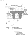
FIG. 1 ] A ofFIG. 1 is a vertical-lateral cross-sectional view illustrating an example of an embodiment of a rubber stopper according to the present invention, which is a cross-sectional view taken along P-P line ofFIG. 4 . B ofFIG. 1 is a partially enlarged view of A ofFIG. 1 . - [
FIG. 2] FIG. 2 is a view illustrating an example of the embodiment of the rubber stopper according to the present invention from a horizonal-lateral direction. - [
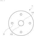
FIG. 3] FIG. 3 is a view illustrating an example of the embodiment of the rubber stopper according to the present invention from a vertical upper direction. - [
FIG. 4] FIG. 4 is a view illustrating an example of the embodiment of the rubber stopper according to the present invention from a vertical lower direction. - Hereinafter, preferred embodiments of the present invention will be explained.
- Embodiments described below are examples of a representative embodiment of the present invention, and the scope of the present invention should not be narrowly interpreted based on these examples.
- As illustrated in
FIG.1 , arubber stopper 1 according to the present invention includes acanopy portion 11 having an upper surface and a lower surface, and aleg portion 12 provided on the lower surface of thecanopy portion 11, in which theleg portion 12 has atapered base portion 10 with an approximately semispherical shape at the center on a lower surface side of the canopy portion, and a curvature radius R1 of thetapered base portion 10 is 2mm or more and 4mm or less. - In the
above Patent Literature 1, a thickness of the canopy portion and a length of the leg portion are approximately the same, and the length of the leg portion is short; therefore, a shape of the leg portion which can secure stability of the rubber stopper in a half-capped state as in a rubber stopper for a lyophilized drug product is not mentioned though the problem of coring is solved, and there is also a problem that there is a tendency to fall over at the time of being conveyed. - Moreover, in the
above Patent Literature 2, the rubber stopper is manufactured using a plurality of rubber materials with different hardnesses; therefore, there is a problem that manufacturing costs are high. - Furthermore, in the above Patent Literature 3, a holding member and a protective lid are necessary in the half-capped posture and the number of components is increased; therefore, there is a problem that manufacturing costs are increased.
- In view of the above, the prevent invention, a prime objective of which is to solve the problem of occurrence of coring, provides a rubber stopper having the shape of the leg portion which can secure stability of the rubber stopper in the half-capped state as in the rubber stopper for the lyophilized drug product, suppressing occurrence of coring even when using a single rubber material with the same hardness, reducing the number of components, and suitable for lyophilization with low manufacturing costs.
- The curvature radius R1 is a radius corresponding to an arc including an apex of the
tapered base portion 10 as illustrated inFIG. 1 . A center point of the curvature radius R1 is on a perpendicular line (central axis) extending from the apex of thetapered base portion 10 toward the center of theleg portion 12, and a start point and an end point of the arc are set as an "R stop portion 1". The "R stop portion 1" is part of a length P of an inner wall of theleg portion 12. When the curvature radius R1 is less than 2mm, the inside of theleg portion 12 becomes too small, and a possibility that a hollow needle scrapes the inner wall of theleg portion 12 to cause coring is increased. Moreover, when the curvature radius R1 exceeds 4mm, a molding defect is likely to occur in theleg portion 12. - The curvature radius R1 is, more preferably, 2mm or more and 3mm or less.
- In the
rubber stopper 1 according to the present invention, occurrence of coring is suppressed in both cases where a plastic needle is used and where a metallic needle is used as a needle as illustrated in later-described examples. In particular, the plastic needle is used for a closed system drug transfer device (CSTD); therefore, therubber stopper 1 according to the present invention can be used also for sealing a drug product for the CSTD. - As a material for forming the
rubber stopper 1 according to the present invention, for example, synthetic rubbers such as a butyl rubber, an isoprene rubber, a butadiene rubber, a halogenated butyl rubber, ethylenepropylene rubber, and a silicone rubber or natural rubber and so on can be cited. The present invention can be also applied to a so-called laminated rubber stopper in which, for example, a film containing fluorine-based resin is laminated on a rubber stopper. As the above fluorine-based resin, for example, a tetrafluoroethylene resin, a chlorotrifluoroethylene resin, a tetrafluoroethylene-hexafluoropropylene copolymer resin, a vinylidene fluoride resin, a vinyl fluoride resin, a tetrafluoroethylene-ethylene copolymer resin, a chlorotrifluoroethylene-ethylene copolymer resin, and the like can be cited. A thickness of the film to be laminated can be, for example, 0.002 mm or more and 0.5 mm or less. Moreover, a hardness of therubber stopper 1 according to the present invention is, for example, 25 to 45, and preferably 28 to 40. - In the present invention, it is preferable that a length P of the inner wall of the leg portion 12 (a length from the apex of the
tapered base portion 10 to a flattening point (see A ofFIG. 1 ) on a ground side of the leg portion 12 (at an inner end of theleg portion 12 in R stop portions 2) is longer than a length D of theleg portion 12 itself (a shortest distance from the lower surface of the canopy portion to a plane to be flat on the ground side of the leg portion 12 (see A ofFIG. 1 )), and is preferably greater than 100% and less than 160% with respect to the length D of theleg portion 12 itself, and is more preferably greater than 100% and less than 145%. According to the above, it is possible to prevent that the film is extended too much when laminating theleg portion 12 and to prevent that a molding defect such as damage of the film is caused. - In the present invention, a distance R2 between the start point and the end point of the arc including the apex of the
tapered base portion 10 is preferably 8 mm or less, and more preferably 6 mm or less. When the distance R2 exceeds 10 mm, moldability is not good, and the film does not easily stick to the leg portion. When the distance R2 is less than 4 mm, a center needle is likely to scrape the inner wall surface, and coring is likely to occur. Note that the distance R2 is a chord length of the arc including the apex of the taperedbase portion 10 obtained by extending a horizontal line from the point of the "R stop portion 1" in a radial direction as illustrated inFIG. 1 . The positions of the start point and the end point of the "R stop portion 1" can be defined by a position of an outer diameter R3 of a later-described recessedportion 111 or the length D of theleg portion 12 itself to be required. Furthermore, the positions of the start point and the end point of the "R stop portion 1" can be defined as the same height as an outer diameter position of an annular protrusion B provided on a lower surface of the canopy portion as illustrated inFIG. 1 , or within a range of ±10% of the height of the outer diameter position of the annular protrusion B. - Moreover, the "
R stop portion 1" preferably exists on a tangent line extending to the central axis (line) in the "R stop portion 2 (on theR stop portion 1 side)" at the inner end of the leg portion. Since there is an inclination in the tangent line connecting the "R stop portion 1" and the "R stop portion 2 (R stop portion 1 side) at the end of the inner wall of the leg portion, the entire length of theleg portion 12 is shortened, and the volume of theleg portion 12 is increased, which can improve stability of theleg portion 12 and can improve stability of theentire rubber stopper 1. When not only the metallic needle but also a hollow needle such as the plastic needle having a larger diameter than the metallic needle is stuck diagonally, coring does not easily occur, and occurrence of coring can be avoided. - Note that as illustrated in
FIG. 1 , there are two points of the "R stop portion 2" on a curved line provided at the inner end of the leg portion, including a flattening point on the ground side of the leg portion 12 (at the inner end of the leg portion 12) and a point on the "R stop portion 1" side. In the present invention, a curvature radius on the curved line connecting two points of the "R stop portion 2" is preferably 0.1 to 1.0 mm, more preferably, approximately 0.5 mm. - Moreover, the relation between the curvature radius R1 and the distance R2 is 2R1 > R2 or 2R1 = R2. Furthermore, the curvature radius R1 and the distance R2 are between the center of the lower surface of the canopy portion and a height (position) of D/2 or higher from the end of the leg portion as illustrated in
FIG. 1 . - As illustrated in
FIG. 1 andFIG. 3 , thecanopy portion 11 has the recessedportion 111 at the center on an upper surface side of the canopy portion, and the outer diameter R3 of the recessedportion 111 is preferably 90% or less with respect to the distance R2. According to the above, occurrence of coring can be further suppressed. - The
canopy portion 11 provided with the recessedportion 111 at the center on the upper surface side of the canopy portion includes aneedle sticking portion 112 to be a bottom surface of the recessedportion 111, into which a needle is stuck, and a thickness E of theneedle sticking portion 112 is preferably 60% or more and less than 100% of a thickness C of the canopy portion. When setting to 60% or more, it is possible to prevent that theneedle sticking portion 112 becomes too thin and is damaged to cause the leakage or the like of a drug solution. When setting to less than 100 %, occurrence of coring can be further suppressed. - In this case, the thickness E of the
needle sticking portion 112 is preferably 3 mm or less. When the thickness E of theneedle sticking portion 112 exceeds 3 mm, the risk of occurrence of coring is increased. Needle sticking resistance generated when sticking the needle is also increased. A lower limit value of the thickness E of theneedle sticking portion 112 is not particularly limited; however, the lower limit value is preferably 1 mm or more for maintaining self-hermeticity and barrier properties. - In this case, the thickness E of the needle sticking portion is preferably 15% or more and 40% or less with respect to the length D of the
leg portion 12 itself. When setting to 15% or more, it is possible to prevent that theneedle sticking portion 112 becomes too thin and damaged and prevent that the leakage or the like of a drug solution occurs. When setting to 40% or less, the risk of occurrence of coring can be suppressed. - As illustrated in
FIG. 4 , it is preferable that theleg portion 12 contains, at the center thereof, a circular-shaped taperedbase portion 10 having the same diameter as theneedle sticking portion 112 and has acutout 13 at one place so that more than half of a circumference that forms the taperedbase portion 10 opens. When thecutout 13 is possessed at one place, a contact area to an inner wall of a lip is increased in the half-capped state as compared with a case of theleg portion 12 having a forked structure in which cutouts are formed at two places; therefore, occurrence of displacement or coming-off of therubber stopper 1 can be suppressed. In order to prevent therubber stopper 1 from coming off from the vial when theleg portion 12 stays standing so as to fit to the lip of a vial in the half-capped state, aconvex portion 121 provided on an outer peripheral surface of theleg portion 12 is in a state of closely contacting the inner wall of the lip firmly, thereby fixing therubber stopper 1. Accordingly, therubber stopper 1 according to the present invention can be used for the lyophilized drug product and has stability even in the half-capped state. Moreover, thecutout 13 is possessed at one place; therefore, therubber stopper 1 itself easily stands by itself, and it is possible to prevent therubber stopper 1 from fall over at the time of being conveyed and to prevent docking in which theleg portions 12 closely contact each other. - A method of filling a pharmaceutical container with the lyophilized drug product is generally performed in the following order of (A) to (C).
- (A) The drug product is put into a body of the pharmaceutical container under sterile conditions.
- (B) Subsequently, lyophilization is performed in a lyophilizer in a state where the lip of the body of the pharmaceutical container is half-capped with the rubber stopper to thereby prevent mixing of foreign matter.
- (C) After lyophilization, fully-capping is performed to seal the container, then, the container is taken out from the lyophilizer.
- As illustrated in
FIG. 2 andFIG. 4 , the tapered and ring-shapedconvex portion 121 is preferably formed on the outer peripheral surface of theleg portion 12 on the end side of the leg portion. According to the above, a tapered-shaped narrow portion functions as a guide for an inner wall surface of the lip of the body of the pharmaceutical container to realize smooth half-capping at the time of half-capping in the above process of (B), the contact area with respect to the inner wall surface of the lip is increased, and therubber stopper 1 is fitted to the pharmaceutical container in a state of being fixed stably and firmly. - Hereinafter, the present invention will be explained further in details based on the example illustrated in
FIG. 1 .
Note that the examples explained below are representative examples of the present invention, and the scope of the present invention should not be narrowly interpreted based on these examples. - A pharmaceutical container for a lyophilized drug product was capped with the rubber stoppers of Example 1 and Example 2, and the number of occurrence of coring was checked by using respective needles illustrated in Table 1 below.
- The
rubber stopper 1 made of chlorinated butyl rubber coated with a fluorine-based resin having the structure illustrated inFIG. 1 was prepared, which includes thecanopy portion 11 having the upper surface and the lower surface, and theleg portion 12 provided on the lower surface of thecanopy portion 11, in which theleg portion 12 has the taperedbase portion 10 at the center on a lower surface side of the canopy portion, and the curvature radius R1 of the taperedbase portion 10 is 2.65 mm. The length P of the inner wall of theleg portion 12 of therubber stopper 1 is a length from the center of the lower surface of the canopy portion on the central axis to the "R stop portion 2" which is a flattening point at the end of the inner wall of the leg portion, which was 13.3 mm. The length D of theleg portion 12 itself was 10.2 mm. The distance R2 of theleg portion 12 on the lower surface side of the canopy portion was 4.6 mm. Furthermore, thecanopy portion 11 is provided with the recessedportion 111 at the center on the upper surface side of the canopy portion, and the outer diameter R3 of the recessedportion 111 was 4.0 mm. Moreover, thecanopy portion 11 has theneedle sticking portion 112 into which the needle is stuck, and the thickness E of theneedle sticking portion 112 was 2.5 mm. - The
rubber stopper 1 made of chlorinated butyl rubber coated with a fluorine-based resin having the structure illustrated inFIG. 1 was prepared, which includes thecanopy portion 11 having the upper surface and the lower surface, and theleg portion 12 provided at the lower surface of thecanopy portion 11, in which theleg portion 12 has the taperedbase portion 10 at the center on a lower surface side of the canopy portion, and the curvature radius R1 of the taperedbase portion 10 is 3.30 mm. The length P of the inner wall of theleg portion 12 of therubber stopper 1 is a length from the center of the lower surface of the canopy portion on the central axis to the "R stop portion 2" which is a flattening point at the end of the inner wall of the leg portion, which was 13.2 mm. The length D of theleg portion 12 itself was 10.3 mm. The distance R2 of theleg portion 12 on the lower surface side of the canopy portion was 5.3 mm. However, thecanopy portion 11 is not provided with the recessedportion 111 at the center on the upper surface side of the canopy portion in the Example 2. Moreover, thecanopy portion 11 has theneedle sticking portion 112 into which the needle is stuck, and the thickness E of theneedle sticking portion 112 was 3.3 mm. - Test results are shown in Table 1 below.
[Table 1] Name of needle manufacturer Needle material Number of occurrence of coring (unit: case) Example 1 Example 2 (Different shape) Company A Plastic 0/50 4/50 Company B Plastic 0/50 4/50 Company C metal 0/50 6/50 - According to the result of the test example 1, it is suggested that occurrence of coring is suppressed by using the
rubber stopper 1 according to the present invention including thecanopy portion 11 having the upper surface and the lower surface, and theleg portion 12 provided on the lower surface of thecanopy portion 11, in which theleg portion 12 has the taperedbase portion 10 at the center on the lower surface side of the canopy portion, and the curvature radius R1 of the taperedbase portion 10 is 2mm or more and 4mm or less. As illustrated in the above Table 1, in therubber stopper 1 according to the present invention, coring was less likely to occur in both cases where the plastic needle is used and where the metal needle is used. Furthermore, it was found that when the thickness E of theneedle sticking portion 112 is set to 3 mm or less, occurrence of coring is further suppressed. - As apparent from the above, according to the present invention, it is possible to provide a rubber stopper that can solve the problem of occurrence of coring, having the shape of the leg portion capable of securing stability of the rubber stopper in the half-capped state as in the rubber stopper for the lyophilized drug product, suppressing occurrence of coring even when using a single rubber material with the same hardness, reducing the number of components, and suitable for lyophilization with low manufacturing costs.
-
- 1 rubber stopper
- 10 tapered base portion
- 11 canopy portion
- 111 recessed portion
- 112 needle sticking portion
- 12 leg portion
- 121 convex portion
- 13 cutout
- R1 curvature radius of tapered base portion
- R2 distance between start point and end point of arc including apex of tapered base portion
- R3 outer diameter of recessed portion
- B annular protrusion
- C thickness of canopy portion
- D length of leg portion itself
- E thickness of needle sticking portion
- A rubber stopper comprising:
- a canopy portion having an upper surface and a lower surface; and
- a leg portion provided on the lower surface of the canopy portion,
- wherein the leg portion has a tapered base portion at the center on a lower surface side of the canopy portion, and
- a curvature radius R1 of the tapered base portion is 2mm or more and 4mm or less.
- The rubber stopper according to
clause 1,
wherein a length P of an inner wall of the leg portion is longer than a length D of the leg portion itself, which is greater than 100% and less than 160% with respect to the length D of the leg portion itself. - The rubber stopper according to
clause 2,
wherein a distance R2 between a start point and an end point of an arc including an apex of the tapered base portion is 8 mm or less. - The rubber stopper according to clause 3,
- wherein the canopy portion has a recessed portion at the center on an upper surface side of the canopy portion, and
- an outer diameter R3 of the recessed portion is 90% or less with respect to the distance R2.
- The rubber stopper according to any one of
clause 1 to 4, - wherein the canopy portion has a needle sticking portion into which a needle is stuck, and
- a thickness E of the needle sticking portion is 60% or more and less than 100% of a thickness C of the canopy portion.
- The rubber stopper according to clause 5,
wherein the thickness E of the needle sticking portion is 3 mm or less. - The rubber stopper according to clause 5 or 6,
wherein the thickness E of the needle sticking portion is 15% or more and 40% or less with respect to the length D of the leg portion itself. - The rubber stopper according to any one of
clauses 1 to 7,
wherein the leg portion has a cutout at least at one place. - The rubber stopper according to clause 8,
wherein the leg portion is provided with a ring-shaped convex portion on an outer peripheral surface on an end side of the leg portion. - The rubber stopper according to any one of
clauses 1 to 9,
wherein the rubber stopper is used for sealing a lyophilized drug product.
Claims (4)
- A rubber stopper (1) comprising:a canopy portion (11) having an upper surface and a lower surface; anda leg portion (12) provided on the lower surface of the canopy portion (11),wherein the leg portion (12) has a tapered base portion (10) at the center on a lower surface side of the canopy portion (11), and a length P of an inner wall of the leg portion (12) is longer than a length D of the leg portion (12) itself, which is greater than 100% and less than 160% with respect to the length D of the leg portion (12) itself.
- The rubber stopper (1) according to claim 1,
wherein the tapered base portion (10) has a curvature radius R1. - The rubber stopper (1) according to claim 2,
wherein ifthe curvature radius R1 is a radius corresponding to an arc including the apex of the tapered base portion (10), the center point of the curvature radius R1 is on a perpendicular line drawn from the apex of the tapered base portion (10) to the center of the leg portion (12), and a start point and an end point of the arc are R stop portions 1,
then,there are two R stop portions 2 on a tangent line extending from the R stop portion 1 toward the tip portion of the leg portion (12),the R stop portions 2 include a point on the R stop portion 1 side and a point flattening at the inner tip of the leg portion (12), andthe R stop portion 1 is on a tangent line extending toward the central axis at the R stop portion 2 on the point flattening at the inner tip of the leg portion (12). - The rubber stopper (1) according to claim 3, wherein a curvature radius of a curve connecting the two R stop portions 2 is 0.1 to 1.0 mm.
Applications Claiming Priority (3)
| Application Number | Priority Date | Filing Date | Title |
|---|---|---|---|
| JP2020214197 | 2020-12-23 | ||
| PCT/JP2021/024472 WO2022137609A1 (en) | 2020-12-23 | 2021-06-29 | Rubber plug |
| EP21909770.6A EP4268789B1 (en) | 2020-12-23 | 2021-06-29 | RUBBER STOPPER |
Related Parent Applications (2)
| Application Number | Title | Priority Date | Filing Date |
|---|---|---|---|
| EP21909770.6A Division EP4268789B1 (en) | 2020-12-23 | 2021-06-29 | RUBBER STOPPER |
| EP21909770.6A Division-Into EP4268789B1 (en) | 2020-12-23 | 2021-06-29 | RUBBER STOPPER |
Publications (2)
| Publication Number | Publication Date |
|---|---|
| EP4552995A2 true EP4552995A2 (en) | 2025-05-14 |
| EP4552995A3 EP4552995A3 (en) | 2025-07-30 |
Family
ID=82158908
Family Applications (2)
| Application Number | Title | Priority Date | Filing Date |
|---|---|---|---|
| EP25167450.3A Pending EP4552995A3 (en) | 2020-12-23 | 2021-06-29 | Rubber plug |
| EP21909770.6A Active EP4268789B1 (en) | 2020-12-23 | 2021-06-29 | RUBBER STOPPER |
Family Applications After (1)
| Application Number | Title | Priority Date | Filing Date |
|---|---|---|---|
| EP21909770.6A Active EP4268789B1 (en) | 2020-12-23 | 2021-06-29 | RUBBER STOPPER |
Country Status (9)
| Country | Link |
|---|---|
| US (1) | US20240300703A1 (en) |
| EP (2) | EP4552995A3 (en) |
| JP (2) | JP7422433B2 (en) |
| KR (1) | KR102870998B1 (en) |
| CN (1) | CN116744885A (en) |
| AU (2) | AU2021405307A1 (en) |
| CA (1) | CA3205974A1 (en) |
| TW (1) | TWI873363B (en) |
| WO (1) | WO2022137609A1 (en) |
Families Citing this family (1)
| Publication number | Priority date | Publication date | Assignee | Title |
|---|---|---|---|---|
| US12425227B2 (en) * | 2022-12-14 | 2025-09-23 | Sap Se | Quantum safe digital signature service |
Citations (1)
| Publication number | Priority date | Publication date | Assignee | Title |
|---|---|---|---|---|
| WO2012090328A1 (en) | 2010-12-28 | 2012-07-05 | ニプロ株式会社 | Rubber stopper for vial |
Family Cites Families (29)
| Publication number | Priority date | Publication date | Assignee | Title |
|---|---|---|---|---|
| US4226334A (en) * | 1978-12-14 | 1980-10-07 | Automatic Liquid Packaging, Inc. | Stopper |
| EP0204486B1 (en) * | 1985-05-28 | 1990-10-17 | Daikyo Gomu Seiko Ltd. | Resin-laminated rubber plugs and manufacture thereof |
| DE3744174A1 (en) * | 1987-12-24 | 1989-07-06 | Helvoet Pharma | FREEZE DRYING PLUG |
| JP2689398B2 (en) * | 1990-08-24 | 1997-12-10 | 株式会社 大協精工 | Rubber compositions and rubber products for pharmaceuticals and medical devices |
| DE4029832A1 (en) * | 1990-09-20 | 1992-03-26 | Duschek Dieter | Closure esp. for pharmaceutical bottles - comprises stopper connected to bottle neck and enclosed by closure cap contg. rupture disc supported by spacer |
| DK0675830T3 (en) * | 1992-12-30 | 2000-07-17 | Abbott Lab | Thin diaphragm plug for blunt insert device |
| AU702451B2 (en) * | 1994-08-03 | 1999-02-18 | Abbott Laboratories | A reseal with a partial perforation and method and apparatus for creating a partial perforation in a reseal |
| JP3172057B2 (en) * | 1995-04-05 | 2001-06-04 | 株式会社大協精工 | Laminated rubber stopper |
| EP0769456B1 (en) * | 1995-10-18 | 2000-08-23 | Daikyo Seiko, Ltd. | A plastic cap and a process for the production of the same |
| JPH10151171A (en) * | 1996-11-25 | 1998-06-09 | Daikyo Seiko:Kk | Sealing device for pharmaceutical containers and medical devices |
| JP2588872Y2 (en) * | 1998-06-15 | 1999-01-20 | 株式会社大協精工 | Rubber stopper for pharmaceuticals |
| US6068150A (en) * | 1999-01-27 | 2000-05-30 | Coulter International Corp. | Enclosure cap for multiple piercing |
| US6659296B2 (en) * | 2000-01-26 | 2003-12-09 | Amersham Health As | Cap for container |
| JP4535605B2 (en) * | 2000-12-01 | 2010-09-01 | 住友ゴム工業株式会社 | Medical rubber stopper |
| JP2002209975A (en) * | 2001-01-19 | 2002-07-30 | Daikyo Seiko Ltd | Laminated rubber stopper for pharmaceutical vials |
| JP4579484B2 (en) | 2002-06-24 | 2010-11-10 | ニプロ株式会社 | Medical rubber stopper with improved liquid leakage |
| JP4372736B2 (en) * | 2004-09-14 | 2009-11-25 | 株式会社大協精工 | Pharmaceutical container set, pharmaceutical container and rubber stopper |
| ATE404451T1 (en) * | 2004-09-14 | 2008-08-15 | Daikyo Seiko Ltd | CONTAINERS FOR MEDICATIONS AND RUBBER CLOSURE |
| FR2912384B1 (en) * | 2007-02-09 | 2009-04-10 | Biocorp Rech Et Dev Sa | CLOSURE DEVICE FOR A CONTAINER, CONTAINER EQUIPPED WITH SUCH A DEVICE AND METHOD FOR CLOSING A LOT OF SUCH A CONTAINER |
| CN201286861Y (en) * | 2008-07-25 | 2009-08-12 | 安徽华峰医药橡胶有限公司 | Zero-silicatization rubber plug |
| JP2011050699A (en) | 2009-09-04 | 2011-03-17 | Daiwa Tokushu Glass Kk | Vial and sealing device used for the same |
| FR2950865B1 (en) * | 2009-10-01 | 2011-10-28 | Raymond A & Cie | LOCKING CAP FOR A COLLARED CONTAINER WITH A FASTENING CAPSULE |
| US9586737B2 (en) * | 2009-10-09 | 2017-03-07 | West Pharmaceutical Services Deutschland Gmbh & Co. Kg | Elastomeric closure with barrier layer and method for its manufacture |
| DE102011050983A1 (en) * | 2010-09-09 | 2012-03-15 | Helvoet Pharma Belgium N.V. | Closing plugs for pharmaceutical applications |
| US8544665B2 (en) * | 2011-04-04 | 2013-10-01 | Genesis Packaging Technologies | Cap systems and methods for sealing pharmaceutical vials |
| US9585811B2 (en) * | 2011-10-11 | 2017-03-07 | Datwyler Pharma Packaging Belgium Nv | Method for producing a crimp cap, crimp cap and container |
| JP6243096B2 (en) * | 2011-11-16 | 2017-12-06 | 株式会社大協精工 | Rubber stopper for vial |
| IL225734A0 (en) * | 2013-04-14 | 2013-09-30 | Medimop Medical Projects Ltd | Ready-to-use drug vial assemblages including drug vial and drug vial closure having fluid transfer member, and drug vial closure therefor |
| JP2017202848A (en) * | 2016-05-11 | 2017-11-16 | 住友ゴム工業株式会社 | Medical rubber plug and manufacturing method of the same |
-
2021
- 2021-06-29 KR KR1020237018843A patent/KR102870998B1/en active Active
- 2021-06-29 WO PCT/JP2021/024472 patent/WO2022137609A1/en not_active Ceased
- 2021-06-29 AU AU2021405307A patent/AU2021405307A1/en not_active Abandoned
- 2021-06-29 CN CN202180084451.6A patent/CN116744885A/en active Pending
- 2021-06-29 TW TW110123745A patent/TWI873363B/en active
- 2021-06-29 EP EP25167450.3A patent/EP4552995A3/en active Pending
- 2021-06-29 US US18/254,727 patent/US20240300703A1/en active Pending
- 2021-06-29 CA CA3205974A patent/CA3205974A1/en active Pending
- 2021-06-29 EP EP21909770.6A patent/EP4268789B1/en active Active
- 2021-06-29 JP JP2022571020A patent/JP7422433B2/en active Active
-
2024
- 2024-01-09 JP JP2024001018A patent/JP7618307B2/en active Active
-
2025
- 2025-06-25 AU AU2025204783A patent/AU2025204783A1/en active Pending
Patent Citations (1)
| Publication number | Priority date | Publication date | Assignee | Title |
|---|---|---|---|---|
| WO2012090328A1 (en) | 2010-12-28 | 2012-07-05 | ニプロ株式会社 | Rubber stopper for vial |
Also Published As
| Publication number | Publication date |
|---|---|
| EP4552995A3 (en) | 2025-07-30 |
| CN116744885A (en) | 2023-09-12 |
| KR102870998B1 (en) | 2025-10-16 |
| EP4268789B1 (en) | 2025-12-31 |
| TW202225052A (en) | 2022-07-01 |
| EP4268789A1 (en) | 2023-11-01 |
| AU2021405307A1 (en) | 2023-06-22 |
| JP2024028405A (en) | 2024-03-04 |
| EP4268789A4 (en) | 2024-12-04 |
| JP7422433B2 (en) | 2024-01-26 |
| US20240300703A1 (en) | 2024-09-12 |
| JPWO2022137609A1 (en) | 2022-06-30 |
| WO2022137609A1 (en) | 2022-06-30 |
| AU2025204783A1 (en) | 2025-07-17 |
| EP4268789C0 (en) | 2025-12-31 |
| KR20230101873A (en) | 2023-07-06 |
| TWI873363B (en) | 2025-02-21 |
| JP7618307B2 (en) | 2025-01-21 |
| CA3205974A1 (en) | 2022-06-30 |
Similar Documents
| Publication | Publication Date | Title |
|---|---|---|
| US11786664B2 (en) | Prefilled container systems | |
| JP4288742B2 (en) | Reusable universal stopper | |
| US20210331824A1 (en) | Piercing Member for Container Access Device | |
| US6957745B2 (en) | Transfer set | |
| JP3380705B2 (en) | Sealed rubber stopper for syringe and container | |
| JP4138238B2 (en) | Container closure system | |
| KR101265034B1 (en) | Medical port | |
| JP5768820B2 (en) | Rubber stopper for vial | |
| US4253459A (en) | Additive transfer unit with stabilized sealing means | |
| JP3219248U (en) | Needleless syringe connector lid and container | |
| JP2009240684A (en) | Method for manufacturing cap and prefilled syringe | |
| WO2016051989A1 (en) | Syringe assembly, pre-filled syringe, seal cap for sheath with puncture needle, and syringe assembly package | |
| EP4552995A2 (en) | Rubber plug | |
| US20180303710A1 (en) | Self-standing drug-filled synthetic resin ampule | |
| US20230414451A1 (en) | Plastic adapter and closed system drug transfer device | |
| JP2013034567A (en) | Plastic-made nozzle cap | |
| US10369295B2 (en) | Syringe assembly, cap, and puncture needle | |
| JP3618744B2 (en) | Thin-walled diaphragm stopper for blunt insertion devices | |
| JP4535605B2 (en) | Medical rubber stopper | |
| JP2006006791A (en) | Sealed rubber stopper for injection nozzle of syringe for both container | |
| EP1600139A1 (en) | Airtight container for storing a liquid, and in particular a medicament, and aseptic process for filing said container | |
| JP2016179117A (en) | Pre-filled syringe | |
| TW202224663A (en) | Plastic adapter and closed drug transfer system which covers a plastic cap and can be safely used in a closed drug transfer system |
Legal Events
| Date | Code | Title | Description |
|---|---|---|---|
| PUAI | Public reference made under article 153(3) epc to a published international application that has entered the european phase |
Free format text: ORIGINAL CODE: 0009012 |
|
| STAA | Information on the status of an ep patent application or granted ep patent |
Free format text: STATUS: THE APPLICATION HAS BEEN PUBLISHED |
|
| AC | Divisional application: reference to earlier application |
Ref document number: 4268789 Country of ref document: EP Kind code of ref document: P |
|
| AK | Designated contracting states |
Kind code of ref document: A2 Designated state(s): AL AT BE BG CH CY CZ DE DK EE ES FI FR GB GR HR HU IE IS IT LI LT LU LV MC MK MT NL NO PL PT RO RS SE SI SK SM TR |
|
| REG | Reference to a national code |
Ref country code: DE Ref legal event code: R079 Free format text: PREVIOUS MAIN CLASS: B65D0051000000 Ipc: A61J0001050000 |
|
| PUAL | Search report despatched |
Free format text: ORIGINAL CODE: 0009013 |
|
| AK | Designated contracting states |
Kind code of ref document: A3 Designated state(s): AL AT BE BG CH CY CZ DE DK EE ES FI FR GB GR HR HU IE IS IT LI LT LU LV MC MK MT NL NO PL PT RO RS SE SI SK SM TR |
|
| RIC1 | Information provided on ipc code assigned before grant |
Ipc: A61J 1/05 20060101AFI20250620BHEP Ipc: B65D 51/00 20060101ALI20250620BHEP |
|
| STAA | Information on the status of an ep patent application or granted ep patent |
Free format text: STATUS: REQUEST FOR EXAMINATION WAS MADE |
|
| 17P | Request for examination filed |
Effective date: 20260129 |