EP4553004A1 - Transstockeur - Google Patents
Transstockeur Download PDFInfo
- Publication number
- EP4553004A1 EP4553004A1 EP23208224.8A EP23208224A EP4553004A1 EP 4553004 A1 EP4553004 A1 EP 4553004A1 EP 23208224 A EP23208224 A EP 23208224A EP 4553004 A1 EP4553004 A1 EP 4553004A1
- Authority
- EP
- European Patent Office
- Prior art keywords
- storage
- retrieval machine
- machine according
- image capture
- retrieval
- Prior art date
- Legal status (The legal status is an assumption and is not a legal conclusion. Google has not performed a legal analysis and makes no representation as to the accuracy of the status listed.)
- Withdrawn
Links
Images




Classifications
-
- B—PERFORMING OPERATIONS; TRANSPORTING
- B65—CONVEYING; PACKING; STORING; HANDLING THIN OR FILAMENTARY MATERIAL
- B65G—TRANSPORT OR STORAGE DEVICES, e.g. CONVEYORS FOR LOADING OR TIPPING, SHOP CONVEYOR SYSTEMS OR PNEUMATIC TUBE CONVEYORS
- B65G1/00—Storing articles, individually or in orderly arrangement, in warehouses or magazines
- B65G1/02—Storage devices
- B65G1/04—Storage devices mechanical
- B65G1/0407—Storage devices mechanical using stacker cranes
-
- B—PERFORMING OPERATIONS; TRANSPORTING
- B65—CONVEYING; PACKING; STORING; HANDLING THIN OR FILAMENTARY MATERIAL
- B65G—TRANSPORT OR STORAGE DEVICES, e.g. CONVEYORS FOR LOADING OR TIPPING, SHOP CONVEYOR SYSTEMS OR PNEUMATIC TUBE CONVEYORS
- B65G1/00—Storing articles, individually or in orderly arrangement, in warehouses or magazines
- B65G1/02—Storage devices
- B65G1/04—Storage devices mechanical
- B65G1/0407—Storage devices mechanical using stacker cranes
- B65G1/0421—Storage devices mechanical using stacker cranes with control for stacker crane operations
-
- B—PERFORMING OPERATIONS; TRANSPORTING
- B66—HOISTING; LIFTING; HAULING
- B66F—HOISTING, LIFTING, HAULING OR PUSHING, NOT OTHERWISE PROVIDED FOR, e.g. DEVICES WHICH APPLY A LIFTING OR PUSHING FORCE DIRECTLY TO THE SURFACE OF A LOAD
- B66F9/00—Devices for lifting or lowering bulky or heavy goods for loading or unloading purposes
- B66F9/06—Devices for lifting or lowering bulky or heavy goods for loading or unloading purposes movable, with their loads, on wheels or the like, e.g. fork-lift trucks
- B66F9/07—Floor-to-roof stacking devices, e.g. "stacker cranes", "retrievers"
-
- B—PERFORMING OPERATIONS; TRANSPORTING
- B66—HOISTING; LIFTING; HAULING
- B66F—HOISTING, LIFTING, HAULING OR PUSHING, NOT OTHERWISE PROVIDED FOR, e.g. DEVICES WHICH APPLY A LIFTING OR PUSHING FORCE DIRECTLY TO THE SURFACE OF A LOAD
- B66F9/00—Devices for lifting or lowering bulky or heavy goods for loading or unloading purposes
- B66F9/06—Devices for lifting or lowering bulky or heavy goods for loading or unloading purposes movable, with their loads, on wheels or the like, e.g. fork-lift trucks
- B66F9/075—Constructional features or details
- B66F9/0755—Position control; Position detectors
Definitions
- the invention relates to a storage and retrieval machine for a high-bay warehouse assigned to the storage and retrieval machine but not belonging to the storage and retrieval machine, the storage and retrieval machine comprising a travel and lifting device which is designed to move the storage and retrieval machine at least in a horizontal longitudinal direction and in the vertical direction, and a load-carrying device with a telescopic fork arrangement which is displaceable relative to the travel and lifting device at least in a transverse direction which is substantially orthogonal to both the longitudinal direction and the vertical direction,
- Such storage and retrieval machines are well known. They are used to store goods arranged on pallets in compartments of high-bay warehouses and to retrieve them from these compartments. Storage and retrieval are preferably automated. However, automation requires that the pallets and the goods arranged on them are in perfect condition and, especially during retrieval, that the pallets are precisely arranged in the compartments. If these requirements are not met, the affected pallet may shift within the high-bay warehouse compartment. In the worst case, the pallet may even be pushed off the crossbar(s) of the high-bay warehouse, which can lead to the pallet jamming or even falling, along with the goods arranged on it.
- the object of the present invention is to further develop a storage and retrieval machine of the type mentioned above in such a way that errors can be detected in advance of the actual retrieval process.
- a storage and retrieval machine of the type mentioned at the outset which further comprises an image capture device which is designed to capture at least one image of a load-carrying device, i.e. the high-bay storage compartment, and comprises an evaluation device which is designed to evaluate the at least one image captured by the image capture device according to at least one predetermined criterion and to output a corresponding evaluation result.
- the inventive development of the storage and retrieval machine makes it possible to output a signal reflecting this evaluation result, at least when a predetermined criterion can be established for a predetermined type of faulty condition of stored pallets, based on which this fault type can be detected, and this fault type is detected by the evaluation device based on the image captured by the image capture device.
- this fault signal the operation of the storage and retrieval machine can be interrupted to give one or more operators the opportunity to take countermeasures against the detected fault. In this way, longer shutdown times can be avoided, which would be caused by the above-described consequences of the pallet tilting or even falling, including the goods arranged on it. Overall, the fault-related shutdown times can thus be shortened, thus increasing the efficiency of the storage and retrieval machine.
- the storage and retrieval machine further comprises a control device which is designed to control the travel and lifting device and/or the telescopic fork arrangement of the load-handling device and/or at least one additionally provided auxiliary device depending on the evaluation result.
- a control device which is designed to control the travel and lifting device and/or the telescopic fork arrangement of the load-handling device and/or at least one additionally provided auxiliary device depending on the evaluation result.
- a predetermined sequence of movements for correcting any errors can be stored in the control device or a memory unit connected thereto.
- the evaluation result is not only a purely qualitative result, i.e., merely indicates whether an error of the type in question is present, but also contains a quantitative statement, i.e., indicates the severity of the error of the type in question.
- the control device can be configured to adapt the sequence of movements stored for correcting or compensating the error depending on a quantitative indication of the error contained in the evaluation result.
- an error message depending on the type of error detected and rectified.
- this does not necessarily have to be issued every time.
- such an error message can be issued in the event of damage to the pallet.
- such an error message does not need to be issued.
- the issuance of an error message does not result in the interruption of the retrieval process. Rather, the damaged pallet can be brought to a specially designated location that is more easily accessible than the high-bay storage compartment, which may well be located at a lofty height, and repaired or replaced there.
- the image capture device comprises at least one camera and/or at least one laser profile sensor and/or at least one ultrasonic sensor.
- the image capture device is arranged so as to be movable relative to the load-carrying device. In this way, it can It can be adjusted between an extended position, in which it is arranged, for example, essentially at the same height as the load-handling device and thus has a favorable viewing angle of the spatial area arranged transversely next to the load-handling device, for example the high-bay warehouse compartment, and a retracted position, in which it is arranged, for example, below the load-handling device. In the retracted position, the image capture device does not interfere with the actual retrieval process, and in this position, the risk of damage to the image capture device during the actual retrieval process is reduced.
- the image captured by the image capture device can be a two- or three-dimensional image, or an image that additionally contains information about the distance of the image point from the image capture device for at least one of its pixels, preferably for a plurality of its pixels, and even more preferably for all of its pixels. This can be achieved, for example, by assigning at least one laser rangefinder to the image capture device.
- the image capture device can capture the spatial area arranged transversely next to the load-handling device from a plurality of viewing directions. This allows the distance information to be calculated from a comparison of the plurality of images, even if these images are only two-dimensional.
- the plurality of viewing directions can be achieved, for example, by the aforementioned mobility of the image capture devices providing at least one intermediate position in addition to the extended position and the retracted position.
- the plurality of viewing directions can also be achieved by moving the image capture device by means of the drives of the travel and lifting device of the storage and retrieval machine.
- the plurality of Viewing directions are realized by providing a plurality of cameras and/or laser profile sensors and/or ultrasonic sensors.
- the distance information obtained in this way can, for example, be used by the evaluation device to determine not only relative distances, but also absolute distances between characteristic points and/or lines on the pallet. It is helpful here that the pallets commonly used in high-bay warehouses have a known, for example, standardized, structure with known, for example, standardized, dimensions.
- the evaluation device for evaluating the at least one image captured by the image capture device comprises a conventional image recognition unit and/or an image recognition unit operating on the basis of artificial intelligence (AI).
- the conventional image recognition unit can, for example, operate on the basis of the recognition of characteristic points and/or lines and/or areas.
- the image recognition unit operating on the basis of artificial intelligence (AI) can have been trained in advance on the basis of a plurality of previously acquired images of spatial areas arranged transversely next to the load-handling device with defective pallets arranged therein.
- a first type of error that can be detected and remedied according to the invention concerns pallets that sag between the crossbars of the high-bay storage bay under the weight of the goods placed on them. This sag reduces the entry opening for the telescopic fork assembly. If the sag is too great, the telescopic fork assembly collides with the second, usually middle, crossboard of the pallet when entering the pallet. As a result, the telescopic fork assembly pushes the pallet off the crossbar or against the push-through protection of the high-bay storage bay.
- the image evaluation unit can use, for example, the position and course of the upper edge as a predetermined criterion of the front crossbar of the high-bay warehouse compartment with the position and course of the lower front edge of the second, usually middle, cross board of the pallet.
- This lower front edge is the one with the greatest probability of collision with the telescopic fork assembly if the pallet is deflected.
- the image evaluation unit determines the distance between the two edges, as this is a measure of the height of the entry opening for the telescopic fork assembly. If this distance falls below a predetermined value, it is determined that a defect of the first type has occurred. The value of the determined distance can be used as a measure of the severity of the defect.
- a second type of error that can be detected and corrected using the invention concerns pallets where nails have come loose on one of the lower longitudinal boards, causing the affected longitudinal board to protrude downward.
- the board When retracting the telescopic fork assembly, there is a risk that the board will get caught at the bottom of the base of the load-handling device on the lifting frame of the stacker crane, causing the pallet to be "pulled” off the telescopic fork assembly again.
- the image analysis unit can compare, for example, the position and profile of the upper edge of the lower longitudinal boards with the position and profile of the lower edge of the associated pallet foot as a predetermined criterion. If these two edges are spaced apart by more than a predetermined value, it is determined that a defect of the second defect type is present. The value of the determined distance can be used as a measure of the severity of the defect.
- this second type of error may only be detected after the pallet has been lifted by the telescopic fork assembly. Once detected, it may be necessary to place the pallet on the crossbars of the high-bay storage bay again before countermeasures can be initiated.
- a third type of error that can be detected and remedied according to the invention concerns pallets that have been placed in the high-bay storage compartment twisted around their vertical axis. This also reduces the available entry opening for the telescopic fork assembly, creating a risk of collision between the telescopic fork assembly and the pallet.
- the image analysis unit can compare, for example, the position and alignment of vertical edges of the pallet feet as a predetermined criterion. For example, the distance between two adjacent edges, be they adjacent edges of adjacent pallet feet or the two edges of one and the same pallet foot, can be considered a measure of the distortion. If this distance exceeds a predetermined value, it is determined that a defect of the third type is present. The value of the determined distance can be used as a measure of the severity of the defect.
- the at least one auxiliary device comprises at least one support element arranged on the storage and retrieval machine, which is adjustable between at least one active position and one passive position, and preferably also height-adjustable.
- the at least one support element can be a support element that can be pivoted or linearly displaced between the passive position and the at least one active position.
- the height adjustability can be active, i.e., brought about by means of a power device, or passive, i.e., derived from another movement.
- the at least one shim element can be arranged in a first active position after lifting the front edge of the pallet between the top side of the front crossbar of the high-bay storage compartment and the undersides of the front ends of the longitudinal boards of the pallet to facilitate the insertion of the telescopic fork assembly.
- the at least one shim element can be arranged in a second active position adjacent to the front side of the front crossbar of the high-bay storage compartment or immediately adjacent to this front side directly below the front ends of the longitudinal boards of the pallet in order to support these longitudinal boards when retracting the telescopic fork assembly and thus prevent it from drooping.
- the image analysis by the evaluation device also offers the possibility of fine shelf positioning, which can be used for precise positioning of the pallet storage location, i.e., the high-bay storage bay.
- fine shelf positioning a hole in the front crossbar of the respective high-bay storage bay is usually searched for using image recognition and used for positioning.
- the evaluation unit provided according to the invention could be oriented to the upper edge of the front crossbar for vertical positioning and to the vertical side edges of the shelf uprights for longitudinal positioning, i.e., in the aisle direction.
- the evaluation device detects that the images captured by the image capture device cannot be evaluated, for example because the field of view is obscured by a hanging piece of plastic film, a corresponding error message can be issued.
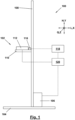
- a storage and retrieval machine according to the invention is generally designated 100.
- the storage and retrieval machine 100 is used for storing and retrieving goods G arranged on pallets P (see Figure 3 ) in storage compartments of a high-bay warehouse known per se and not belonging to the invention, the cross bars R of which are schematically indicated in some figures (see for example Figure 2 ).
- the storage and retrieval machine 100 comprises a travel and lifting device 102 with a horizontal rail 104 that extends in the longitudinal direction L (also called the X direction) of an aisle arranged between two shelves, a base unit 106 that can be moved along the rail 104 in the longitudinal direction L, a vertical rail 108 attached to the base unit 106 that extends in the height direction H (also called the Y direction) and can be moved together with the base unit 106 in the longitudinal direction L, and a lifting carriage 110 that can be moved in the height direction along the vertical rail 108.
- the drives for the travel in the longitudinal and height directions can be arranged in the base unit 106.
- the lifting carriage 110 carries a load-carrying device 112 with a telescopic fork arrangement 114, which can extend from the lifting carriage 110 in the transverse direction Q (also called Z direction) into the shelf compartments in order to store goods G arranged on pallets P there or to retrieve them from them.
- a load-carrying device 112 with a telescopic fork arrangement 114, which can extend from the lifting carriage 110 in the transverse direction Q (also called Z direction) into the shelf compartments in order to store goods G arranged on pallets P there or to retrieve them from them.
- the storage and retrieval machine 100 further comprises an image capture device 116, for example a camera, which is designed to capture at least one image of a storage compartment arranged in the transverse direction Q next to the load-handling device 112, and an evaluation device 118 which is designed to evaluate the at least one image captured by the image capture device 116 according to at least one predetermined criterion and to output a corresponding evaluation result.
- an image capture device 116 for example a camera, which is designed to capture at least one image of a storage compartment arranged in the transverse direction Q next to the load-handling device 112
- an evaluation device 118 which is designed to evaluate the at least one image captured by the image capture device 116 according to at least one predetermined criterion and to output a corresponding evaluation result.
- the evaluation result can, for example, be output in the form of an error signal that calls an operator to correct the error.
- the storage and retrieval machine 100 can further comprise a control device 120, which is designed to control the travel and lifting device 102 and/or the telescopic fork arrangement 114 of the load-handling device 112 and/or at least one additionally provided auxiliary device 122 (see, for example, Figures 4c to 4f ) depending on the evaluation result.
- a control device 120 which is designed to control the travel and lifting device 102 and/or the telescopic fork arrangement 114 of the load-handling device 112 and/or at least one additionally provided auxiliary device 122 (see, for example, Figures 4c to 4f ) depending on the evaluation result.
- the control device 120 is in Figure 1 shown as a separate unit. However, it is understood that it can also be designed as part of the overall control system of the storage and retrieval machine 100.
- These pallets P comprise nine pallet feet PF arranged in a 3x3 grid. They further comprise three longitudinal boards PL, each of which is connected to the underside of three of the pallet feet PF, and three transverse boards PQ, each of which is connected to the top side of three of the pallet feet PF. Additional support boards PT are attached to the transverse boards PQ, on which the goods G can be placed.
- a pallet P is stored in a storage compartment, its transverse boards PQ extend in the longitudinal direction L of the storage and retrieval machine 100, and its longitudinal boards PL and support boards PT extend in the transverse direction Q of the storage and retrieval machine 100.
- a first type of error that can be detected and corrected according to the invention relates to Figure 4a Pallets P, which are under the weight of the arranged goods G between the crossbars Q of the storage compartment. This deflection reduces the entry opening for the telescopic fork assembly 114. If the deflection is too large, the telescopic fork assembly 114 collides with the second, usually middle, crossboard PQ of the pallet P when entering the pallet P, which results in Figure 4a indicated by a star. As a result, the telescopic fork assembly 114 pushes the pallet P from the front (in Fig. 4a right) crossbar, or against the push-through protection of the high-bay storage compartment (not shown).
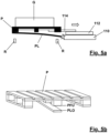
- a second type of error that can be detected and corrected according to the invention concerns Figure 5a Pallets P where nails have come loose on one of the lower longitudinal boards PL, so that the affected longitudinal board PL protrudes downwards.
- Figure 5a Pallets P where nails have come loose on one of the lower longitudinal boards PL, so that the affected longitudinal board PL protrudes downwards.
- a third type of error that can be detected and corrected according to the invention concerns Figure 6a Pallets P, which have been placed in the high-bay storage compartment rotated around the vertical axis. This also reduces the available entry opening for the telescopic fork assembly 114, so that there is a risk of a collision between the telescopic fork assembly 114 and the pallet P, which in Figure 6a indicated by a star.
- the image evaluation unit 118 can use a predetermined criterion according to Figure 4b For example, compare the position and course of the upper edge RO of the front crossbar R of the high-bay storage compartment with the position and course of the lower front edge PQV of the second, usually middle, cross board PQ of the pallet P. With this lower front edge PQV, there is the greatest probability of a collision with the telescopic fork arrangement 114 in the event of a deflection of the pallet P.
- the image evaluation unit 118 determines the distance between the two edges, since it is a measure for the height of the insertion channel EK for the telescopic fork assembly 114. If this distance falls below a predetermined value, it is determined that a defect of the first type is present. The value of the determined distance can be used as a measure of the severity of the defect.
- an auxiliary device 122 is used, which is arranged on the lifting carriage 110 of the storage and retrieval machine 100 and comprises a support element 124, which is movable relative to the lifting carriage 110 in the transverse direction Q (cf. Figures 4c and 4d ) and in the height direction H (compare Figures 4d and 4e ) is adjustable.
- the pallet P is first lifted by means of the telescopic fork assembly 114 at its Figure 4c right end.
- the support element 124 is then moved in such a way that its Figure 4d left end is arranged above the front crossbar R. Now the pallet P is placed on the support element 124 ( Figure 4e ).
- the height of the insertion channel EK increases such that the telescopic fork assembly 114 can finally be fully inserted into the pallet P and the pallet P can be properly lifted ( Figure 4f ).
- an alternative auxiliary device 122' is used, namely an auxiliary device 122' with a support element 124' that can be pivoted about the height direction H.
- auxiliary device 122' with a support element 124' that can be pivoted about the height direction H.
- a tiltability of the load-carrying device 112 about an axis extending in the longitudinal direction L relative to the lifting carriage 110 can be used, as is already known from the prior art.
- Figure 4i by tilting the load-carrying device 112 in this way see arrow pointing upwards
- the same effect can be achieved as in the first and second strategies by placing the support element 124 or 124 ⁇ underneath, namely a de facto increase in the height of the insertion channel EK, so that the telescopic fork arrangement 114 is fully inserted into the pallet P ( Figure 4i ) and the pallet P after the load handling device 112 has been tilted back (see arrow pointing downwards in Figure 4j ) can be lifted properly.
- the image evaluation unit 118 can Figure 5b For example, as a predetermined criterion, compare the position and profile of the upper edge PLO of the lower longitudinal boards PL with the position and profile of the lower edge PFU of the associated pallet foot PF. If these two edges are spaced apart by more than a predetermined value, it is determined that a defect of the second type exists. The value of the determined distance can be used as a measure of the severity of the defect.
- the auxiliary device 122 with the support element 124 is also used in the strategy for correcting the second type of error.
- the support element 124 is used to support the loose longitudinal board PL of the pallet P (see Figure 5d ), so that this remains even after lifting the pallet P (see Figure 5e ) cannot hang down.
- the image evaluation unit 118 can Figure 6b
- the position and course of vertical edges PFV of the pallet feet PF can be compared as a predetermined criterion.
- the distance between two adjacent edges be they adjacent edges PFV1 and PFV2 of adjacent pallet feet PF or the two edges PFV2 and PFV3 of one and the same pallet foot PF, can be considered a measure of the torsion. If this distance exceeds a predetermined value, it is determined that a defect of the third type is present. The value of the determined distance can be used as a measure of the severity of the defect.
- Figure 6c a pivoting of the load-handling device 112 about an axis running in the vertical direction H relative to the lifting carriage 110 can be used, as is already known from the prior art.
- the storage and retrieval machine 100 is also moved in the longitudinal direction L in order to properly insert the telescopic fork assembly 114 into the insertion channels EK (see Figure 6b ) of the pallet P.
- the image capture device 116 can be designed to be adjustable in the height direction H.
- a retracted position can also be seen.
- a laser rangefinder can be integrated into the image capture device 116 in order to also assign distance information to the individual pixels.
Landscapes
- Engineering & Computer Science (AREA)
- Transportation (AREA)
- Structural Engineering (AREA)
- Mechanical Engineering (AREA)
- Civil Engineering (AREA)
- Life Sciences & Earth Sciences (AREA)
- Geology (AREA)
- Warehouses Or Storage Devices (AREA)
Priority Applications (1)
| Application Number | Priority Date | Filing Date | Title |
|---|---|---|---|
| EP23208224.8A EP4553004A1 (fr) | 2023-11-07 | 2023-11-07 | Transstockeur |
Applications Claiming Priority (1)
| Application Number | Priority Date | Filing Date | Title |
|---|---|---|---|
| EP23208224.8A EP4553004A1 (fr) | 2023-11-07 | 2023-11-07 | Transstockeur |
Publications (1)
| Publication Number | Publication Date |
|---|---|
| EP4553004A1 true EP4553004A1 (fr) | 2025-05-14 |
Family
ID=88731315
Family Applications (1)
| Application Number | Title | Priority Date | Filing Date |
|---|---|---|---|
| EP23208224.8A Withdrawn EP4553004A1 (fr) | 2023-11-07 | 2023-11-07 | Transstockeur |
Country Status (1)
| Country | Link |
|---|---|
| EP (1) | EP4553004A1 (fr) |
Citations (3)
| Publication number | Priority date | Publication date | Assignee | Title |
|---|---|---|---|---|
| US20070103107A1 (en) * | 2005-11-04 | 2007-05-10 | Murata Kikai Kabushiki Kaisha | Control device for movable body |
| US20190210802A1 (en) * | 2016-02-18 | 2019-07-11 | Daifuku Co., Ltd. | Article Transport Apparatus |
| WO2022144039A1 (fr) * | 2020-12-28 | 2022-07-07 | 上海快仓智能科技有限公司 | Robot de transport, procédé de commande de transport, dispositif de commande et système d'entrepôt |
-
2023
- 2023-11-07 EP EP23208224.8A patent/EP4553004A1/fr not_active Withdrawn
Patent Citations (3)
| Publication number | Priority date | Publication date | Assignee | Title |
|---|---|---|---|---|
| US20070103107A1 (en) * | 2005-11-04 | 2007-05-10 | Murata Kikai Kabushiki Kaisha | Control device for movable body |
| US20190210802A1 (en) * | 2016-02-18 | 2019-07-11 | Daifuku Co., Ltd. | Article Transport Apparatus |
| WO2022144039A1 (fr) * | 2020-12-28 | 2022-07-07 | 上海快仓智能科技有限公司 | Robot de transport, procédé de commande de transport, dispositif de commande et système d'entrepôt |
Similar Documents
| Publication | Publication Date | Title |
|---|---|---|
| EP3875990B1 (fr) | Système d'inspection d'un dépôt | |
| DE102016208995B4 (de) | Regalsystem umfassend eine Anordnung zur Konturenkontrolle von in ein Regalsystem einzulagernden Paletten | |
| EP1716060A1 (fr) | Procede et systeme pour se servir d'un rayon dans un dispositif de preparation des commandes | |
| DE202008009631U1 (de) | Regallager | |
| EP2746193B1 (fr) | Véhicule pour entrepôt, transstockeur, entrepôt et procédé correspondant | |
| DE102021006362B4 (de) | Zentrierstation und Verfahren zum Handhaben zumindest eines Ladungsträgers | |
| EP4553004A1 (fr) | Transstockeur | |
| DE102020111767A1 (de) | Regalbediengerät | |
| EP1234785B1 (fr) | Magasin à rayonnage | |
| DE10004232A1 (de) | Antriebseinrichtung für eine Lagervorrichtung | |
| DE20004435U1 (de) | Vorrichtung zum lagenweisen Stapeln und Entstapeln von Behältern | |
| EP0470538B1 (fr) | Rayonnage pour le stockage d'écarteurs profilés pour vitres isolantes | |
| DE202004002338U1 (de) | System zum Bedienen eines Regals vorzugsweise in einer Kommissionieranlage | |
| DE202006006539U1 (de) | Lagerlift | |
| DE102021200698A1 (de) | Lager- und Entnahmesystem sowie Behälter für ein Lager- und Entnahmesystem | |
| EP3974350A1 (fr) | Procédé de fonctionnement d'un système d'entreposage sur étag?res et système d'entreposage sur étag?res | |
| DE202020005100U1 (de) | Magazinsystem, insbesondere Werkzeugmagazin | |
| EP3874988A1 (fr) | Étagère à palettes | |
| DE102023212314A1 (de) | Regalbedienvorrichtung, Regalsystem und Verfahren zur Montage eines Regalsystems | |
| DE102023212313A1 (de) | Regalbedienvorrichtung, Regalsystem und Verfahren zur Montage eines Regalsystems | |
| EP0450534A1 (fr) | Appareil de commande pour rayonnage du type grue pour matériel sous forme de barres | |
| DE102024125074A1 (de) | System, bestehend aus einem Flurförderfahrzeug und einem Regal | |
| EP4428063A1 (fr) | Système de stockage et de prélèvement et procédé de fonctionnement d'un système de stockage et de prélèvement | |
| DE102022132081A1 (de) | Regalbediengerät und Verfahren zur Ermittlung einer Belegung von Regalfächern eines Lagerregals | |
| DE102023212315A1 (de) | Verfahren für einen sicheren Zugang zu einem Gefahrenbereich in einem Regalsystem, Regelungseinheit, Computerprogrammprodukt und Sicherungsmittel |
Legal Events
| Date | Code | Title | Description |
|---|---|---|---|
| PUAI | Public reference made under article 153(3) epc to a published international application that has entered the european phase |
Free format text: ORIGINAL CODE: 0009012 |
|
| STAA | Information on the status of an ep patent application or granted ep patent |
Free format text: STATUS: THE APPLICATION HAS BEEN PUBLISHED |
|
| AK | Designated contracting states |
Kind code of ref document: A1 Designated state(s): AL AT BE BG CH CY CZ DE DK EE ES FI FR GB GR HR HU IE IS IT LI LT LU LV MC ME MK MT NL NO PL PT RO RS SE SI SK SM TR |
|
| STAA | Information on the status of an ep patent application or granted ep patent |
Free format text: STATUS: THE APPLICATION IS DEEMED TO BE WITHDRAWN |
|
| 18D | Application deemed to be withdrawn |
Effective date: 20251115 |