EP4553020A1 - Procédé pour transférer des piles de produits plats d'une voie de transport réglable en hauteur à une palette - Google Patents
Procédé pour transférer des piles de produits plats d'une voie de transport réglable en hauteur à une palette Download PDFInfo
- Publication number
- EP4553020A1 EP4553020A1 EP23208486.3A EP23208486A EP4553020A1 EP 4553020 A1 EP4553020 A1 EP 4553020A1 EP 23208486 A EP23208486 A EP 23208486A EP 4553020 A1 EP4553020 A1 EP 4553020A1
- Authority
- EP
- European Patent Office
- Prior art keywords
- pallet
- conveyor line
- gripping device
- robot arm
- robot
- Prior art date
- Legal status (The legal status is an assumption and is not a legal conclusion. Google has not performed a legal analysis and makes no representation as to the accuracy of the status listed.)
- Pending
Links
Images
Classifications
-
- B—PERFORMING OPERATIONS; TRANSPORTING
- B65—CONVEYING; PACKING; STORING; HANDLING THIN OR FILAMENTARY MATERIAL
- B65G—TRANSPORT OR STORAGE DEVICES, e.g. CONVEYORS FOR LOADING OR TIPPING, SHOP CONVEYOR SYSTEMS OR PNEUMATIC TUBE CONVEYORS
- B65G61/00—Use of pick-up or transfer devices or of manipulators for stacking or de-stacking articles not otherwise provided for
-
- B—PERFORMING OPERATIONS; TRANSPORTING
- B25—HAND TOOLS; PORTABLE POWER-DRIVEN TOOLS; MANIPULATORS
- B25J—MANIPULATORS; CHAMBERS PROVIDED WITH MANIPULATION DEVICES
- B25J9/00—Program-controlled manipulators
- B25J9/16—Program controls
- B25J9/1679—Program controls characterised by the tasks executed
- B25J9/1687—Assembly, peg and hole, palletising, straight line, weaving pattern movement
-
- B—PERFORMING OPERATIONS; TRANSPORTING
- B25—HAND TOOLS; PORTABLE POWER-DRIVEN TOOLS; MANIPULATORS
- B25J—MANIPULATORS; CHAMBERS PROVIDED WITH MANIPULATION DEVICES
- B25J9/00—Program-controlled manipulators
- B25J9/16—Program controls
- B25J9/1694—Program controls characterised by use of sensors other than normal servo-feedback from position, speed or acceleration sensors, perception control, multi-sensor controlled systems, sensor fusion
-
- B—PERFORMING OPERATIONS; TRANSPORTING
- B65—CONVEYING; PACKING; STORING; HANDLING THIN OR FILAMENTARY MATERIAL
- B65G—TRANSPORT OR STORAGE DEVICES, e.g. CONVEYORS FOR LOADING OR TIPPING, SHOP CONVEYOR SYSTEMS OR PNEUMATIC TUBE CONVEYORS
- B65G57/00—Stacking of articles
- B65G57/02—Stacking of articles by adding to the top of the stack
- B65G57/03—Stacking of articles by adding to the top of the stack from above
-
- B—PERFORMING OPERATIONS; TRANSPORTING
- B25—HAND TOOLS; PORTABLE POWER-DRIVEN TOOLS; MANIPULATORS
- B25J—MANIPULATORS; CHAMBERS PROVIDED WITH MANIPULATION DEVICES
- B25J13/00—Controls for manipulators
- B25J13/08—Controls for manipulators by means of sensing devices, e.g. viewing or touching devices
- B25J13/085—Force or torque sensors
-
- B—PERFORMING OPERATIONS; TRANSPORTING
- B65—CONVEYING; PACKING; STORING; HANDLING THIN OR FILAMENTARY MATERIAL
- B65G—TRANSPORT OR STORAGE DEVICES, e.g. CONVEYORS FOR LOADING OR TIPPING, SHOP CONVEYOR SYSTEMS OR PNEUMATIC TUBE CONVEYORS
- B65G2201/00—Indexing codes relating to handling devices, e.g. conveyors, characterised by the type of product or load being conveyed or handled
- B65G2201/02—Articles
- B65G2201/0288—Signatures, i.e. sections of printed magazines, papers or books
-
- B—PERFORMING OPERATIONS; TRANSPORTING
- B65—CONVEYING; PACKING; STORING; HANDLING THIN OR FILAMENTARY MATERIAL
- B65G—TRANSPORT OR STORAGE DEVICES, e.g. CONVEYORS FOR LOADING OR TIPPING, SHOP CONVEYOR SYSTEMS OR PNEUMATIC TUBE CONVEYORS
- B65G2203/00—Indexing code relating to control or detection of the articles or the load carriers during conveying
- B65G2203/02—Control or detection
- B65G2203/0266—Control or detection relating to the load carrier(s)
-
- B—PERFORMING OPERATIONS; TRANSPORTING
- B65—CONVEYING; PACKING; STORING; HANDLING THIN OR FILAMENTARY MATERIAL
- B65G—TRANSPORT OR STORAGE DEVICES, e.g. CONVEYORS FOR LOADING OR TIPPING, SHOP CONVEYOR SYSTEMS OR PNEUMATIC TUBE CONVEYORS
- B65G2203/00—Indexing code relating to control or detection of the articles or the load carriers during conveying
- B65G2203/04—Detection means
- B65G2203/042—Sensors
-
- G—PHYSICS
- G05—CONTROLLING; REGULATING
- G05B—CONTROL OR REGULATING SYSTEMS IN GENERAL; FUNCTIONAL ELEMENTS OF SUCH SYSTEMS; MONITORING OR TESTING ARRANGEMENTS FOR SUCH SYSTEMS OR ELEMENTS
- G05B2219/00—Program-control systems
- G05B2219/30—Nc systems
- G05B2219/39—Robotics, robotics to robotics hand
- G05B2219/39102—Manipulator cooperating with conveyor
-
- G—PHYSICS
- G05—CONTROLLING; REGULATING
- G05B—CONTROL OR REGULATING SYSTEMS IN GENERAL; FUNCTIONAL ELEMENTS OF SUCH SYSTEMS; MONITORING OR TESTING ARRANGEMENTS FOR SUCH SYSTEMS OR ELEMENTS
- G05B2219/00—Program-control systems
- G05B2219/30—Nc systems
- G05B2219/40—Robotics, robotics mapping to robotics vision
- G05B2219/40006—Placing, palletize, un palletize, paper roll placing, box stacking
-
- G—PHYSICS
- G05—CONTROLLING; REGULATING
- G05B—CONTROL OR REGULATING SYSTEMS IN GENERAL; FUNCTIONAL ELEMENTS OF SUCH SYSTEMS; MONITORING OR TESTING ARRANGEMENTS FOR SUCH SYSTEMS OR ELEMENTS
- G05B2219/00—Program-control systems
- G05B2219/30—Nc systems
- G05B2219/40—Robotics, robotics mapping to robotics vision
- G05B2219/40586—6-DOF force sensor
Definitions
- the invention relates to a method for transferring stacks of flat products from a conveyor line whose height is adjustable to a pallet having the features of the preamble of claim 1.
- the invention lies in the technical field of the graphic industry and there in particular in the field of handling (e.g. gripping, holding, moving, rotating, turning and/or setting down) stacks of superimposed, flexible and preferably printed and folded flat products such as folded sheets, preferably made of paper, cardboard, paperboard, plastic or composite material, with a manipulator, in particular an articulated arm robot/articulated arm robot with robot arm and gripper device for the stacks.
- handling e.g. gripping, holding, moving, rotating, turning and/or setting down
- stacks of superimposed, flexible and preferably printed and folded flat products such as folded sheets, preferably made of paper, cardboard, paperboard, plastic or composite material
- a manipulator in particular an articulated arm robot/articulated arm robot with robot arm and gripper device for the stacks.
- the DE102020103398A1 discloses a conveyor line for stacks of printed products lying on top of each other and a robot with a robot arm including a gripper for picking up the stack from the conveyor line and for placing the stacks on pallets.
- the robot can be designed as an industrial articulated-arm robot.
- a sensor arranged on the robot can detect the height of a transport stack to be built.
- the sensor can be arranged on a gripping device.
- the sensor can be a distance sensor or a camera.
- the document does not describe the conveyor line being height-adjustable; however, such conveyor lines are usually height-adjustable in order to be able to connect them to folding machines of different heights.
- the DE202019106975U1 also discloses a conveyor line for stacks of printed products lying one above the other and a so-called collaborative robot system with a robot arm including a gripper for picking up the stacks from the conveyor line and placing the stacks on pallets.
- the FR3110152B1 also discloses a conveyor line and a robot-guided gripper head.
- the gripper head comprises a vertically movable upper gripping element, which is designed as a clamping element, and a horizontally movable lower gripping element, which is designed as a pair of prongs.
- the DE112019000170B4 discloses a robot arm for placing workpieces, the robot arm comprising a force sensor for detecting an abnormality in transferring the workpieces.
- the US 11597092B1 discloses a robot arm with a force sensor which is used to detect the position and orientation of a flying object.
- a method for transferring stacks of flat products from a conveyor line whose height is adjustable to a pallet, with a robot arm, wherein the robot arm comprises a gripping device and the robot arm lifts the stacks with the gripping device from the conveyor line at a pick-up position and sets them down on the pallet at a set-down position, is characterized in that the robot arm comprises at least one force sensor and that a set height position of the conveyor line and/or an assumed height position of the pallet is measured using the force sensor to determine a contact force with the conveyor line or with the pallet and/or that a set or assumed height or horizontal position of a stop (49) is measured using the force sensor (15) to determine a contact force with the stop (49).
- the invention advantageously makes it possible to deposit stacks of flat products lying on top of each other without collisions and without errors.
- the invention is used, for example, in connection with folding machines or their delivery.
- the invention further offers the advantage that a force sensor of the robot is used, thus eliminating the need for an additional sensor, such as a distance sensor. This is particularly advantageous when using a so-called collaborative robot, since such robots usually already have an internal force sensor.
- the invention therefore also offers a cost-effective solution.
- the relative (height) positions of a conveyor line, a pallet or a pallet stack to each other and to the (height) positions of a robot arm or a gripping device on the robot arm can be advantageously recorded, processed and stored for the subsequent movement of the robot arm.
- a stop can be provided according to the invention.
- the stop can be arranged on the conveyor line or on another device whose position (horizontal and/or vertical) is relevant for the robot movements when carrying out the method for transferring stacks of flat products, e.g., on a container for (pallet stack) intermediate layers or on a wall near the pallet, against which the stacks can be aligned during placement.
- the method can be advantageously used to determine the positions of the conveyor line and the pallet (or the pallet stack or the angular position of the pallet) as part of a robot training program and to save them for later collision-free movements of the robot when transferring the stacks, i.e., when picking up and setting down the stacks.
- a training program can be started automatically for each new transfer process or at the operator's request, especially when loading newly positioned pallets or when the robot is used on a different conveyor line.
- the invention therefore uses the robot arm and its force sensors as a measuring instrument to measure height position.
- developments Preferred developments of the invention (hereinafter referred to as “developments”) are described below. These can also be combined with one another where not technically impossible.
- the starting position is preferably above the conveyor line or the pallet.
- a further development can be characterized in that the gripping device is moved from the specified starting position in or against the z-direction until the gripping device touches the conveyor line or the pallet.
- the contact is preferably made in such a way that neither the robot (arm) nor the conveyor line or the pallet or a pallet stack are damaged; also, the conveyor line or the pallet or the pallet stack should not be displaced upon contact.
- a further development can be characterized in that a target force value is specified and the gripping device is moved from the specified starting position in or against the z-direction until an actual force value measured by the force sensor matches or exceeds the target force value.
- a preferably digital computer can be used for this purpose.
- a further development can be characterized in that the movement of the gripping device is stopped as soon as the actual force value measured by the force sensor matches or exceeds the target force value.
- the computer can then cause the robot controller to execute a corresponding movement.
- a further development can be characterized by the gripping device being in an end position when stopped.
- a further development can be characterized in that the end position when determining the height position of the conveyor line on the vertical axis is located a value Delta_Z1 away from Z0.
- a further development can be characterized in that the value Delta_Z1 is provided by a device for determining the position of the robot arm.
- a further development can be characterized in that the The final position when determining the height position of the pallet on the vertical axis is a value Delta_Z2 away from Z0.
- the value Delta_Z2 is provided by a device for determining the position of the robot arm.
- the device for determining the position can comprise the force sensor and a preferably digital computing unit.
- a further development can be characterized in that the gripping device is moved downwards when determining the set height position of the conveyor line and/or the assumed height position of the pallet.
- a further development can be characterized in that the gripping device is moved vertically downwards.
- a further development can be characterized in that the gripping device performs a linear movement.
- a further development can be characterized by the height position Z1 being taken into account when moving the gripper device to the pick-up position when lifting the stack. Knowing the height position Z1, the gripper device can, for example, be moved to a specified position above the height position Z1.
- a further development can be characterized by the fact that the height position Z2 is taken into account when moving the gripper device to the settling position when depositing the stack. Knowing the height position Z1, the gripper device can, for example, be moved to a specified position above the height position Z2.
- a further development can be characterized in that an angular position of the pallet is determined by measuring three height positions Z2a, Z2b, and Z2c at three different positions on the pallet. Each individual measurement of the three height positions can be carried out according to the method according to the invention and its further developments.
- a further development can be characterized in that a height position Z3 of an already formed pallet stack is measured on the pallet at at least one position of the pallet stack.
- the measurement of the height position can be carried out according to the method according to the invention and its further developments.
- a further development can be characterized in that the robot is a robot of a collaborative robot system and that the force sensor is a force sensor arranged inside the robot arm to provide collaborative functions.
- a further development can be characterized in that multiple force sensors are arranged.
- the robot arm is preferably part of a robot system, which usually also includes a robot base and which can be designed as a conventional industrial robot with fencing for operator protection, in particular as an articulated-arm robot with three to seven axes of rotation, or as a so-called collaborative robot system, in particular as a so-called cobot.
- the latter does not require fencing, as the system has its own sensors and uses these to detect contact with operating personnel and prevent possible injuries, e.g., by automatically stopping the robot arm movement.
- a collaborative robot system can also be implemented using an industrial robot with an additional area scanner (detection of operating personnel in the danger zone) and an automatic stop function.
- a further development can be characterized by the robot arm being designed as an articulated arm.
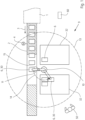
- Figure 1 shows a schematic representation of a plan view of a device when carrying out a preferred embodiment of a method according to the invention.
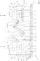
- Figure 2 shows a schematic representation of a side view of a device when carrying out a preferred embodiment of a method according to the invention.
- Figure 1 shows a detail of a machine 1 of the graphic industry, preferably a further processing machine 1 and in particular a folding machine 1, and a preferably linear conveyor line 2 arranged downstream of the machine, e.g. a roller table 2 with transport rollers 5, with a conveying direction 3 and with a motor 4 for the preferably horizontal conveying of successive stacks 6 of superimposed products, e.g. printed and folded sheets of paper 6.
- a machine 1 of the graphic industry preferably a further processing machine 1 and in particular a folding machine 1
- a preferably linear conveyor line 2 arranged downstream of the machine, e.g. a roller table 2 with transport rollers 5, with a conveying direction 3 and with a motor 4 for the preferably horizontal conveying of successive stacks 6 of superimposed products, e.g. printed and folded sheets of paper 6.
- Figure 1 a device 9 according to the invention for transferring the stacks 6, in particular for depositing the stacks 6 on pallets 32.
- the device 9 comprises a robot 10 with a movable robot arm 11, e.g. an articulated arm 11, on which a gripping tool 20 is arranged for gripping individual stacks 6.
- a danger zone 13 is defined by the maximum movements of the robot arm 11.
- the gripping tool 20 grips a stack 6 at a time, lifts it from the conveyor line 2 and holds the stack 6 during the robot movement to a pallet 32.
- the stacks 6 conveyed away from the machine 1 are thus deposited one after the other on the pallet 32 and form there (next to one another and one above the other according to a arranged according to the predetermined settling pattern) a pallet stack 33.
- the stacks 6 of an upper (and preferably complete) level form an upper edge of the pallet stack 33.
- two pallets 32 are placed on one long side of the conveyor line 2.
- the robot 10 is also placed on the long side of the conveyor line 2; alternatively, it could also be arranged at the end of the conveyor line 2.
- the two pallets 32 can be loaded with stacks 6 one after the other; alternatively, the two pallets 32 can also be loaded alternately.
- a control device 60 is provided, which controls the movements of the robot when moving the stacks.
- FIG. 2 shows the device 9 in action.
- the robot arm 11 of the robot 10 repeatedly performs a depositing movement 14.
- the gripper head 20 is in a position 20a close to the conveyor line 2 and during depositing, it is in a position 20b close to the pallet 32.
- the deposited individual stacks 6 successively form a pallet stack 33 on the pallet 32.
- the robot arm 11 comprises several joints 12 and is thus freely movable in space.
- the robot arm 11 comprises at least one sensor 15, which is designed as a force sensor 15, ie as a force-measuring sensor.
- the robot arm 11 and thus also the gripping device 20 carry out a respective measuring movement 40 (preferably linear and vertically downward), which starts in a respective (upper) starting position 41 and ends in a respective (lower) end position 42.
- the respective starting position 41 can be predetermined and automatically approached by the robot arm 11 when the measuring process starts.
- the respective end position 42 is reached when the force sensor 15 of the robot arm 11 strikes, i.e. a predetermined target force value is reached or exceeded; this is preferably the case when the gripping device 20 touches the conveyor line 2, the pallet 32 or the pallet stack 33.
- the respective measuring movement 40 serves to measure a height position 43 of the conveyor line 2 (value Z1), a height position 44 of the pallet 32 (value Z2), or a height position 48 of the pallet stack 33 (value Z3); or the angular position of the plate in space (triple values Z2a, Z2b, Z2c), e.g., relative to a horizontal line.
- the respective height position Z1, Z2, Z2a, Z2b, and/or Z2c then corresponds to the respective end position 42. All (height) values are to be understood as values on a Z-axis or vertical axis 46; the zero point can be defined at the (height) level of a floor 47 of the production facility.
- Figure 2 also shows an example of a stop 49. This can be arranged, for example, on a wall 70 near the pallet 32. The robot arm 11 or the gripper device 20 can be moved against this stop to determine the contact force.
Landscapes
- Engineering & Computer Science (AREA)
- Mechanical Engineering (AREA)
- Robotics (AREA)
- Manipulator (AREA)
- Stacking Of Articles And Auxiliary Devices (AREA)
Priority Applications (2)
| Application Number | Priority Date | Filing Date | Title |
|---|---|---|---|
| EP23208486.3A EP4553020A1 (fr) | 2023-11-08 | 2023-11-08 | Procédé pour transférer des piles de produits plats d'une voie de transport réglable en hauteur à une palette |
| CN202411586733.8A CN119953856A (zh) | 2023-11-08 | 2024-11-08 | 将面状产品堆垛从高度可调的传送线转移至托盘的方法 |
Applications Claiming Priority (1)
| Application Number | Priority Date | Filing Date | Title |
|---|---|---|---|
| EP23208486.3A EP4553020A1 (fr) | 2023-11-08 | 2023-11-08 | Procédé pour transférer des piles de produits plats d'une voie de transport réglable en hauteur à une palette |
Publications (1)
| Publication Number | Publication Date |
|---|---|
| EP4553020A1 true EP4553020A1 (fr) | 2025-05-14 |
Family
ID=88745830
Family Applications (1)
| Application Number | Title | Priority Date | Filing Date |
|---|---|---|---|
| EP23208486.3A Pending EP4553020A1 (fr) | 2023-11-08 | 2023-11-08 | Procédé pour transférer des piles de produits plats d'une voie de transport réglable en hauteur à une palette |
Country Status (2)
| Country | Link |
|---|---|
| EP (1) | EP4553020A1 (fr) |
| CN (1) | CN119953856A (fr) |
Citations (7)
| Publication number | Priority date | Publication date | Assignee | Title |
|---|---|---|---|---|
| DE102013001110A1 (de) * | 2013-01-22 | 2014-08-07 | Weber Maschinenbau Gmbh Breidenbach | Roboter mit einer Handhabungseinheit |
| DE202019106975U1 (de) | 2019-05-07 | 2020-01-09 | Maschinenbau Oppenweiler Binder Gmbh & Co. Kg | Handhabungsvorrichtung für Produktstapel |
| DE102020207368A1 (de) * | 2019-06-17 | 2020-12-17 | Kabushiki Kaisha Toshiba | Objekthandhabungssteuervorrichtung, Objekthandhabungsvorrichtung, Objekthandhabungsverfahren und Computerprogrammprodukt |
| DE112019000170B4 (de) | 2018-10-30 | 2021-07-01 | Mujin, Inc. | Steuerungssystem, Transportvorrichtung, Programm und Steuerungsverfahren |
| DE102020103398A1 (de) | 2020-02-11 | 2021-08-12 | Heidelberger Druckmaschinen Aktiengesellschaft | Verfahren zum Bewegen eines Produktstapels mit einem Roboter |
| FR3110152B1 (fr) | 2020-05-18 | 2022-05-27 | Recmi Ind | Dispositif et procede de palettisation |
| US11597092B1 (en) | 2020-03-26 | 2023-03-07 | Amazon Technologies, Ine. | End-of-arm tool with a load cell |
-
2023
- 2023-11-08 EP EP23208486.3A patent/EP4553020A1/fr active Pending
-
2024
- 2024-11-08 CN CN202411586733.8A patent/CN119953856A/zh active Pending
Patent Citations (7)
| Publication number | Priority date | Publication date | Assignee | Title |
|---|---|---|---|---|
| DE102013001110A1 (de) * | 2013-01-22 | 2014-08-07 | Weber Maschinenbau Gmbh Breidenbach | Roboter mit einer Handhabungseinheit |
| DE112019000170B4 (de) | 2018-10-30 | 2021-07-01 | Mujin, Inc. | Steuerungssystem, Transportvorrichtung, Programm und Steuerungsverfahren |
| DE202019106975U1 (de) | 2019-05-07 | 2020-01-09 | Maschinenbau Oppenweiler Binder Gmbh & Co. Kg | Handhabungsvorrichtung für Produktstapel |
| DE102020207368A1 (de) * | 2019-06-17 | 2020-12-17 | Kabushiki Kaisha Toshiba | Objekthandhabungssteuervorrichtung, Objekthandhabungsvorrichtung, Objekthandhabungsverfahren und Computerprogrammprodukt |
| DE102020103398A1 (de) | 2020-02-11 | 2021-08-12 | Heidelberger Druckmaschinen Aktiengesellschaft | Verfahren zum Bewegen eines Produktstapels mit einem Roboter |
| US11597092B1 (en) | 2020-03-26 | 2023-03-07 | Amazon Technologies, Ine. | End-of-arm tool with a load cell |
| FR3110152B1 (fr) | 2020-05-18 | 2022-05-27 | Recmi Ind | Dispositif et procede de palettisation |
Also Published As
| Publication number | Publication date |
|---|---|
| CN119953856A (zh) | 2025-05-09 |
Similar Documents
| Publication | Publication Date | Title |
|---|---|---|
| EP1847490B1 (fr) | Dispositif et procédé de palettisation et/ou de dépalettisation automatique de réservoirs | |
| DE3718601C2 (fr) | ||
| EP3865436B1 (fr) | Procédé de déplacement d'un empilement de produits à l'aide d'un robot | |
| DE102007016727B4 (de) | Verfahren zum mehrlagigen Bestapeln eines Trägers | |
| EP3144255A1 (fr) | Dispositif destine a reconditionner des marchandises au detail regroupees en emballages unitaires | |
| EP3680922B1 (fr) | Procédé et système de positionnement permettant de fabriquer des noyaux de transformateur | |
| EP3865437B1 (fr) | Procédé de déplacement d'un empilement de produits à l'aide d'un robot | |
| EP4010276B1 (fr) | Dispositif et procédé de manutention et/ou de manipulation d'au moins une rangée de marchandises de détail en défilement | |
| DE102009011301B4 (de) | Verfahren und Greifer zur Handhabung eines Gebindes mittels eines Manipulators | |
| DE102017107215A1 (de) | Verfahren zur Bewegung eines zur Handhabung von flächigen Zuschnitten ausgebildeten Saug- und/oder Greifinstrumentes sowie Vorrichtung mit einem solchen Saug- und/oder Greifinstrument | |
| EP3865439A1 (fr) | Dispositif de déplacement d'un empilement de produits à l'aide d'un robot | |
| EP4553020A1 (fr) | Procédé pour transférer des piles de produits plats d'une voie de transport réglable en hauteur à une palette | |
| EP4553023A1 (fr) | Dispositif pour soulever et déplacer une pile de produits plats superposés | |
| DE102023127584B3 (de) | Verfahren zum Bereitstellen eines Stapels übereinanderliegender Druckprodukte für eine Kontrolle | |
| DE102023124514B4 (de) | Verfahren zum Abheben eines Stapels von einer Förderstrecke mit einem Roboterarm | |
| EP3865438A1 (fr) | Procédé de déplacement d'un empilement de produits à l'aide d'un robot | |
| DE29712663U1 (de) | Vorrichtung zum Stapeln und Entstapeln | |
| DE102023134359A1 (de) | Verfahren zum Ansteuern eines Palettiersystems vor Erreichen von Ende einer Positionierfläche, Computerprogrammprodukt sowie Palettiersystem | |
| EP2773580B1 (fr) | Dispositif de transport et de manutention de produits | |
| DE4331605A1 (de) | Transportvorrichtung für auf Paletten aufgestapeltes bogenförmiges Material | |
| EP4474319A1 (fr) | Station de dépalettisation pour suremballage et système d'emballage | |
| DE102025103099A1 (de) | Vorrichtung zum Anheben und Bewegen eines Stapels übereinander liegender flacher Produkte | |
| DE102025136437A1 (de) | Vorrichtung und Verfahren zum Entstapeln eines Stapels | |
| DE102023134351A1 (de) | Hubvorrichtung, Palettiersystem, Ansteuerverfahren zum Ansteuern eines Palettiersystems sowie Computerprogrammprodukt | |
| DE4024884C2 (de) | Einrichtung zum Ausrichten von Blechpaketen auf einem Transportmittel |
Legal Events
| Date | Code | Title | Description |
|---|---|---|---|
| PUAI | Public reference made under article 153(3) epc to a published international application that has entered the european phase |
Free format text: ORIGINAL CODE: 0009012 |
|
| STAA | Information on the status of an ep patent application or granted ep patent |
Free format text: STATUS: THE APPLICATION HAS BEEN PUBLISHED |
|
| AK | Designated contracting states |
Kind code of ref document: A1 Designated state(s): AL AT BE BG CH CY CZ DE DK EE ES FI FR GB GR HR HU IE IS IT LI LT LU LV MC ME MK MT NL NO PL PT RO RS SE SI SK SM TR |
|
| P01 | Opt-out of the competence of the unified patent court (upc) registered |
Free format text: CASE NUMBER: APP_32277/2025 Effective date: 20250703 |
|
| STAA | Information on the status of an ep patent application or granted ep patent |
Free format text: STATUS: REQUEST FOR EXAMINATION WAS MADE |
|
| 17P | Request for examination filed |
Effective date: 20251114 |