EP4553021A1 - Dispositif de support de bobine pour configuration à double empilement - Google Patents
Dispositif de support de bobine pour configuration à double empilement Download PDFInfo
- Publication number
- EP4553021A1 EP4553021A1 EP23209293.2A EP23209293A EP4553021A1 EP 4553021 A1 EP4553021 A1 EP 4553021A1 EP 23209293 A EP23209293 A EP 23209293A EP 4553021 A1 EP4553021 A1 EP 4553021A1
- Authority
- EP
- European Patent Office
- Prior art keywords
- support device
- receiving surface
- abutment
- labelling
- abutment surface
- Prior art date
- Legal status (The legal status is an assumption and is not a legal conclusion. Google has not performed a legal analysis and makes no representation as to the accuracy of the status listed.)
- Pending
Links
Images





Classifications
-
- B—PERFORMING OPERATIONS; TRANSPORTING
- B65—CONVEYING; PACKING; STORING; HANDLING THIN OR FILAMENTARY MATERIAL
- B65H—HANDLING THIN OR FILAMENTARY MATERIAL, e.g. SHEETS, WEBS, CABLES
- B65H19/00—Changing the web roll
- B65H19/10—Changing the web roll in unwinding mechanisms or in connection with unwinding operations
- B65H19/12—Lifting, transporting, or inserting the web roll; Removing empty core
- B65H19/123—Lifting, transporting, or inserting the web roll; Removing empty core with cantilever supporting arrangements
-
- B—PERFORMING OPERATIONS; TRANSPORTING
- B65—CONVEYING; PACKING; STORING; HANDLING THIN OR FILAMENTARY MATERIAL
- B65H—HANDLING THIN OR FILAMENTARY MATERIAL, e.g. SHEETS, WEBS, CABLES
- B65H2701/00—Handled material; Storage means
- B65H2701/50—Storage means for webs, tapes, or filamentary material
- B65H2701/53—Adaptations of cores or reels for special purposes
- B65H2701/534—Stackable or interlockable reels or parts of reels
-
- B—PERFORMING OPERATIONS; TRANSPORTING
- B65—CONVEYING; PACKING; STORING; HANDLING THIN OR FILAMENTARY MATERIAL
- B65H—HANDLING THIN OR FILAMENTARY MATERIAL, e.g. SHEETS, WEBS, CABLES
- B65H2801/00—Application field
- B65H2801/75—Labelling machines
Definitions
- the present invention relates to a support device for a reel of web of labelling material for the use in a labelling machine configured for labelling articles adapted to contain a pourable product, preferably a pourable food product.
- Labelling machines are known, which are commonly used to prepare, transport and apply labels onto articles, such as bottles, flacons or containers of this sort, destined to be filled with a pourable product, in particular a pourable food product.
- glued labels i.e. portions of a labelling material that are cut at appropriate lengths from a web of labelling material initially wound in form of continuous strip around one or more reels and then sprinkled with glue.
- labels of the tubular type known as "sleeve labels” and obtained starting from a web of heat-shrinking film wound in form of a continuous strip around one or more storage reels; the sleeve labels are applied with a certain clearance on the respective articles and then heated in an oven to obtain their shrinking and perfect adhesion to the lateral surfaces of the articles themselves.
- sleeves labels are also labels of the tubular type, known as "sleeve labels" and obtained starting from a web of heat-shrinking film wound in form of a continuous strip around one or more storage reels; the sleeve labels are applied with a certain clearance on the respective articles and then heated in an oven to obtain their shrinking and perfect adhesion to the lateral surfaces of the articles themselves.
- These types of labels do not require the use of glue.
- a known labelling machine typically comprises:
- a labelling module typically comprises:
- the labelling module further comprises a gluing roller for sequentially spreading glue the onto labels, prior to their application onto the relative articles.
- labelling machines of the above type further comprise a reel feeding system associated with the labelling module and configured to supply the labelling module, and in particular the one or more support shafts thereof, with reels of labelling material.
- the reel feeding system comprises a storage unit having a longitudinal axis and adapted for storing a plurality of reels axially stacked on top of one another.
- Labelling machines configured to apply labels of different sizes, and in particular of different transversal widths, are increasingly widespread.
- the storage unit must be configured to accommodate reels of different sizes, namely reels with different axial widths.
- the need is felt in the sector for minimizing the space allocated for the stacked reels in the known storage units and/or for maximizing the use of the available space in the known storage units, while also increasing the autonomy of the respective labelling module and, ultimately, of the labelling machines of the aforementioned type.
- number 1 indicates as a whole a labelling machine for labelling articles 2, such as bottles, flacons, cans or containers of this sort, adapted to contain a pourable product, preferably a pourable food product.
- labelling machine 1 is configured to apply labels 3 obtained from a web 4 of labelling material onto articles 2.
- labels 3 are glued labels, i.e. strips of labelling material that are cut at predetermined lengths from web 4 and then sprinkled with glue before their application on the respective articles 2, according to a manner known and not described in detail.
- Web 4 is provided in the form of a continuous strip initially wound around reels 5 and is progressively unwound, in use, off each reel 5, according to a known manner.
- labelling machine 1 comprises:
- Labelling module 7 comprises:
- Labelling module 7 further comprises a glue roller of the known type (not shown) for sprinkling each label 3 with glue prior to its application onto the respective article 2.
- Labelling module 7 may also comprise a splicing device 13 configured for splicing the terminal portion of a first web 4 with the initial portion of a second web 4, according to a manner known and not described in detail.
- first web 4 is unwound from the respective first reel 5 in use, a new second reel 5, and hence a new web 4 (i.e. the second web 4) must be fed to labelling module 7, in order to correctly perform the splicing operation.
- labelling machine 1 comprises a reel feeding system 14 for supplying reels 5 to labelling module 7.
- Feeding system 14 comprises a storage unit 15 configured for storing a plurality of reels 5.
- storage unit 15 has a longitudinal axis and is configured for storing reels 5 axially stacked (in a coaxial manner) one on top of the other.
- storage unit 15 comprises a plurality of reel support devices 16, which are adapted to be axially stacked on top of one another.
- storage unit 15 includes at least a first support device 16a and a second support device 16b, axially stacked one on top of the other.
- storage unit 15 is defined by at least two support devices 16 stacked one on top of the other.
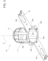
- support device 16 comprises:
- hub 17 extends axially from base 18.
- base 18 includes two arms 18a which radially protrude from hub 17, and in particular from an axial end portion of hub 17 opposite from an axial free end portion of hub 17.
- support device 16 is configured to support the respective reel 5 by means of base 18, whereby the flat part of such reel 5, i.e. the circular base of such reel 5, rests on arms 18a.
- the hub 17 is configured to engage a central through hole of the supported reel 5.
- support device 16 comprises:
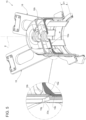
- the support device 16 is configured for receiving a further support device 16 selectively onto the first receiving surface 19a, by abutment between such first receiving surface 19a and the first abutment surface 19b of the further support device 16, whereby a first axial distance D1 is defined between the base 18 of the support device 16 and the base 18 of the further support device 16, or onto the second receiving surface 20a, by abutment between such second receiving surface 20a and the second abutment surface 20b of the further support device 16, whereby a second axial distance D2 is defined between the base 18 of the support device 16 and the base 18 of the further support device 16, the second axial distance D2 being different than the first axial distance D1.
- the support device 16 is configured to be axially stacked with the further support device 16 selectively by abutment between its first receiving surface 19a and the first abutment surface 19b of the further support device 16 for defining a first stacking configuration ( Figures 4 and 5 ) whereby said first axial distance D1 is defined between the respective bases 18 of the support device 16 and the further support device 16, or by abutment between its second receiving surface 20a and the second abutment surface 20b of said further support device 16 for defining a second stacking configuration ( Figures 6 and 7 ) whereby said second axial distance D2 is defined between the respective bases 18 of the support device 16 and the further support device 16.
- first receiving surface 19a is configured to receive in abutment the first abutment surface 19b of the further support device 16 for defining such first stacking configuration
- second receiving surface 20a is configured to receive in abutment the second abutment surface 20b of the further support device 16 for defining such second stacking configuration
- storage unit 15 comprises at least a first support device 16a and a second support device 16b, which are stacked on top of one another, preferably in a coaxial manner.
- second support device 16b is stacked on top of first support device 16a.
- the first receiving surface 19a of the first support device 16a is configured to receive (in abutment) the first abutment surface 19b of the second support device 16b for defining the aforementioned first axial distance D1 between the respective bases 18 of the first support device 16a and of the second support device 16b.
- the second receiving surface 20a of the first support device 16a is configured to receive the second abutment surface 20b of the second support device 16b for defining the aforementioned second axial distance D2 between the respective bases 18 of the first support device 16a and second support device 16b.
- the second axial distance D2 is larger than the first axial distance D1.
- the support device 16 is configured such that:
- the support device 16 is configured such that the first stacking configuration is activatable by arranging the first support device 16a and the second support device 16b in a stacked condition whereby they are at the aforementioned first angular mutual orientation, and such that the second stacking configuration is activatable by arranging the first support device 16a and the second support device 16b in a stacked condition whereby they are at the aforementioned second angular mutual orientation.
- the storage unit 15 is configured to selectively assume a first stacking configuration, whereby:
- the storage unit 15 may accommodate both large-sized reels 5 ( Figure 9 ) and small-sized reels 5 while always maximizing the use of the available space therein ( Figure 8 ).
- a large-sized reel 5 is defined as a reel 5 having an axial width corresponding at most to the second axial distance D2
- a small-sized reel 5 is defined as a reel 5 having an axial width corresponding at most to the first axial distance D1.
- first support device 16a in the storage unit 15 and then stack a second support device 16b on top of first support device 16a by selecting/activating the second stacking configuration.
- the second axial distance D2 is then established between the bases 18 of the first support device 16a and second support device 16b, which is appropriate for accommodating the large-sized reel 5 (supported by the first support device 16a).
- first support device 16a in the storage unit 15 and then stack a second support device 16b on top of first support device 16a by selecting/activating the first stacking configuration.
- the first axial distance D1 is then established between the bases 18 of the first support device 16a and second support device 16b, which is appropriate for accommodating the small-sized reel 5 (supported by the first support device 16a).
- the support device 16 allows for maximizing the use of the available space in storage unit 15.
- the second receiving surface 20a is arranged in a position radially more external than the first receiving surface 19a ( Figure 2 ), and the second abutment surface 20b is arranged in a position radially more external than the first abutment surface 19b ( Figure 3 ) .
- This peculiar structural feature enables the implementation of the selection between the first stacking configuration and the second stacking configuration in a simple manner, as better explained below.
- the first receiving surface 19a, the first abutment surface 19b, the second receiving surface 20a and the second abutment surface 20b are axial, so that said abutment between the first receiving surface 19a and the first abutment surface 19b is defined in the axial direction and so that that said abutment between the second receiving surface 20a and the second abutment surface 20b is defined in the axial direction.
- the first receiving surface 19a, the first abutment surface 19b, the second receiving surface 20a and the second abutment surface 20b are obtained on the central hub 17.
- the second receiving surface 20a and the second abutment surface 20b extend about the central axis X in a discontinued manner.
- the second receiving surface 20a includes a plurality of portions which are separated from one another by axial passages 21, are angularly distributed about the central axis X and are angularly interspersed with the passages 21 (which are in turn angularly distributed about axis X).
- the second abutment surface 20b includes a plurality of portions separated from one another and angularly distributed about the central axis X.
- the support device 16a is configured such that each passage 21 can be crossed by a respective portion of the second abutment surface 20b of the further support device 16, so as to allow the abutment between the first receiving surface 19a and the first abutment surface 19b ( Figure 4 ).
- the support device 16 is configured such that its passages 21 are axially aligned with, and crossed by, the respective portions of the second abutment surfaces 20b of the further support device 16, while the first stacking configuration is being set with the support device 16 and the further support device 16 adopting the first mutual orientation.
- the support device 16 is configured such that when the support device 16 and the further support device 16 (and for example the first support device 16a and the second support device 16b) are arranged at the aforementioned second angular mutual orientation, each portion of the second receiving surface 20a is axially aligned with a respective portion of the second abutment surface 20b of said further support device 16, for defining said second stacking configuration.
- first mutual angular orientation can correspond to a plurality of first angular orientations
- second mutual angular orientation can correspond to a plurality of second angular orientations
- the selection between the first stacking configuration and the second stacking configuration can be performed in an easy and simple manner, minimizing the errors in selecting between such two configurations.
- small-sized reels 5 and/or large-sized reels 5 can be stored in storage unit 15 in a very straightforward way, while also minimizing the occupied space in storage unit 15.
- feeding system 14 further comprises a gripping device 22 (for example a robotic arm) configured to sequentially grip each support device 16 at the central hub 17 thereof for transferring the respective reel 5 from the storage unit 15 to the labelling module 7.
- the gripping device 22 can be part of a robot or part of a cobot.
- feeding system 14 includes a sensor for detecting the size of each reel 5, and a control unit.
- control unit is configured to control a movement of the gripping device 22 based on the information received by the sensor, so as to impart to the relative support device 16 the correct orientation, thereby selecting/activating the first stacking configuration or the second stacking configuration.
- the support device 16 allows to implement a method for stacking reels 5 of labelling material for the labelling of articles 2 adapted to contain a pourable product, the method comprising the steps of:
- the space allocated for the stacked reels 5 in the storage unit 15 can be minimized, thereby maximizing the use of the available space therein.
- this allows for increasing the autonomy of the labelling module 7 and, ultimately, of the labelling machine 1, because the increase in available space in storage unit 15 allows for a larger number of reels 5 to be stored therein.
Landscapes
- Replacement Of Web Rolls (AREA)
Priority Applications (2)
| Application Number | Priority Date | Filing Date | Title |
|---|---|---|---|
| EP23209293.2A EP4553021A1 (fr) | 2023-11-13 | 2023-11-13 | Dispositif de support de bobine pour configuration à double empilement |
| PCT/EP2024/080059 WO2025103728A1 (fr) | 2023-11-13 | 2024-10-24 | Dispositif de support de bobine pour configuration d'empilement double |
Applications Claiming Priority (1)
| Application Number | Priority Date | Filing Date | Title |
|---|---|---|---|
| EP23209293.2A EP4553021A1 (fr) | 2023-11-13 | 2023-11-13 | Dispositif de support de bobine pour configuration à double empilement |
Publications (1)
| Publication Number | Publication Date |
|---|---|
| EP4553021A1 true EP4553021A1 (fr) | 2025-05-14 |
Family
ID=88793257
Family Applications (1)
| Application Number | Title | Priority Date | Filing Date |
|---|---|---|---|
| EP23209293.2A Pending EP4553021A1 (fr) | 2023-11-13 | 2023-11-13 | Dispositif de support de bobine pour configuration à double empilement |
Country Status (2)
| Country | Link |
|---|---|
| EP (1) | EP4553021A1 (fr) |
| WO (1) | WO2025103728A1 (fr) |
Citations (1)
| Publication number | Priority date | Publication date | Assignee | Title |
|---|---|---|---|---|
| EP3760550A1 (fr) * | 2019-07-04 | 2021-01-06 | Sidel Participations | Unité de transfert de bobines de matériau d'étiquetage |
-
2023
- 2023-11-13 EP EP23209293.2A patent/EP4553021A1/fr active Pending
-
2024
- 2024-10-24 WO PCT/EP2024/080059 patent/WO2025103728A1/fr active Pending
Patent Citations (1)
| Publication number | Priority date | Publication date | Assignee | Title |
|---|---|---|---|---|
| EP3760550A1 (fr) * | 2019-07-04 | 2021-01-06 | Sidel Participations | Unité de transfert de bobines de matériau d'étiquetage |
Also Published As
| Publication number | Publication date |
|---|---|
| WO2025103728A1 (fr) | 2025-05-22 |
Similar Documents
| Publication | Publication Date | Title |
|---|---|---|
| CN107548376B (zh) | 用于输送、提供和更换带有卷绕在其上的扁平和/或薄膜材料的卷筒的方法和设备 | |
| US3765991A (en) | Labeling apparatus | |
| EP3760550A1 (fr) | Unité de transfert de bobines de matériau d'étiquetage | |
| EP3718913A1 (fr) | Machine d'étiquetage conçue pour appliquer des étiquettes sur des articles contenant un produit pouvant être versé | |
| US9309016B2 (en) | Automatic container orientation systems and methods | |
| CN117068502A (zh) | 用于传送容器的带有轮的传送装置、用于将柔性载体施加到多个容器的机器和方法 | |
| CN212922305U (zh) | 贴标单元和用于贴标单元的自动调节系统 | |
| EP0450821A2 (fr) | Machine et méthode à étiqueter | |
| US20250353636A1 (en) | Web feeding system for a labelling module for preparing the splicing operation | |
| CN110997503B (zh) | 容器贴标签机 | |
| EP4553021A1 (fr) | Dispositif de support de bobine pour configuration à double empilement | |
| EP4490088B1 (fr) | Installation et procédé permettant l'étiquetage de bobines de matériau en bande | |
| CN112930305B (zh) | 贴标机和在自动贴标过程中处理卷材状贴标材料的方法 | |
| US4588344A (en) | Roll transfer robot | |
| US6616780B1 (en) | Method and device for supplying labels to labeling device | |
| US4575016A (en) | Continuous ribbon feed method and system | |
| WO2026032495A1 (fr) | Système d'alimentation en bande pour un module d'étiquetage pour préparer l'opération d'épissage avec fonction de pulvérisation | |
| EP4703307A1 (fr) | Système d'alimentation en bande avec élément de recouvrement sur la partie avant de la bande | |
| CN109927988B (zh) | 一种保鲜膜卷自动包装机 | |
| WO2020114766A1 (fr) | Machine à étiqueter, procédé de manipulation d'un matériau d'étiquetage de type bande dans un processus d'étiquetage automatisé, et étiquette | |
| EP4520674A1 (fr) | Tambour de transfert d'étiquettes avec des dispositifs de tampon monobloc pour étiqueter des récipients au moyen d'étiquettes partielles | |
| CA2391556A1 (fr) | Methode et dispositif d'alimentation en etiquettes de dispositif d'etiquetage | |
| EP3988462A1 (fr) | Machine d'étiquetage et procédé pour appliquer des étiquettes sur des articles conçus pour contenir un produit versable | |
| EP4509415A1 (fr) | Machine d'étiquetage conçue pour étiqueter des récipients au moyen d'étiquettes partielles par application coulissante | |
| EP3115308A1 (fr) | Appareil et procédé d'application d'étiquette |
Legal Events
| Date | Code | Title | Description |
|---|---|---|---|
| PUAI | Public reference made under article 153(3) epc to a published international application that has entered the european phase |
Free format text: ORIGINAL CODE: 0009012 |
|
| STAA | Information on the status of an ep patent application or granted ep patent |
Free format text: STATUS: THE APPLICATION HAS BEEN PUBLISHED |
|
| AK | Designated contracting states |
Kind code of ref document: A1 Designated state(s): AL AT BE BG CH CY CZ DE DK EE ES FI FR GB GR HR HU IE IS IT LI LT LU LV MC ME MK MT NL NO PL PT RO RS SE SI SK SM TR |
|
| STAA | Information on the status of an ep patent application or granted ep patent |
Free format text: STATUS: REQUEST FOR EXAMINATION WAS MADE |
|
| 17P | Request for examination filed |
Effective date: 20251105 |
|
| STAA | Information on the status of an ep patent application or granted ep patent |
Free format text: STATUS: EXAMINATION IS IN PROGRESS |
|
| 17Q | First examination report despatched |
Effective date: 20260219 |