EP4553032A1 - Dispositif d'entraînement à chaîne et élévateur à pignon à chaîne double - Google Patents
Dispositif d'entraînement à chaîne et élévateur à pignon à chaîne double Download PDFInfo
- Publication number
- EP4553032A1 EP4553032A1 EP23208259.4A EP23208259A EP4553032A1 EP 4553032 A1 EP4553032 A1 EP 4553032A1 EP 23208259 A EP23208259 A EP 23208259A EP 4553032 A1 EP4553032 A1 EP 4553032A1
- Authority
- EP
- European Patent Office
- Prior art keywords
- chain
- chain drive
- link
- sprockets
- links
- Prior art date
- Legal status (The legal status is an assumption and is not a legal conclusion. Google has not performed a legal analysis and makes no representation as to the accuracy of the status listed.)
- Granted
Links
Images


Classifications
-
- B—PERFORMING OPERATIONS; TRANSPORTING
- B66—HOISTING; LIFTING; HAULING
- B66D—CAPSTANS; WINCHES; TACKLES, e.g. PULLEY BLOCKS; HOISTS
- B66D1/00—Rope, cable, or chain winding mechanisms; Capstans
- B66D1/28—Other constructional details
- B66D1/30—Rope, cable, or chain drums or barrels
-
- B—PERFORMING OPERATIONS; TRANSPORTING
- B66—HOISTING; LIFTING; HAULING
- B66D—CAPSTANS; WINCHES; TACKLES, e.g. PULLEY BLOCKS; HOISTS
- B66D3/00—Portable or mobile lifting or hauling appliances
- B66D3/18—Power-operated hoists
- B66D3/26—Other details, e.g. housings
Definitions
- the invention relates to a hoist with a double chain wheel, in which more than one link chain is used as a support means.
- the invention relates to a chain drive arrangement with a chain drive on a chain drive shaft that is drivable by a motor, wherein at least two link chain strands can be guided via the chain drive, as well as to a hoist device in which such a hoist device is connected to a motor directly or via a gear.
- the invention further relates to a hoist system that includes a hoist device and link chain strands guided via the chain drive of the hoist device, and a stop device that can be attached to the ends of the link chain strands.
- link chains in particular industrial round steel chains or profile steel chains—are used as load-bearing means for lifting and/or moving loads.
- the chain links of a chain strand are guided over a sprocket (also referred to as a chain sprocket), with the links of the chain strand being oriented alternately in a vertical and horizontal position on the outer surface of the sprocket.
- the chain drive comprises two sprockets arranged side by side on a shaft of the chain drive, with each of the sprockets being designed to guide a respective section of a link chain strand with alternating horizontal and vertical links, namely with pockets for receiving horizontal links and with a circumferential groove for receiving vertical links.
- the load-bearing capacity and safety against chain breakage are naturally of particular importance.
- the chain drive arrangement in the hoist with a single chain strand can be converted to a two-strand version of the link chain according to the pulley principle, e.g., with a deflection pulley for deflecting the chain.
- Multiple strands can also be implemented to triple or multiply the load capacity.
- the disadvantage of this is that the chain must also be guided over deflection pulleys under full load.
- the invention proposes that, in a chain drive arrangement, the chain drive has two or more sprockets arranged side by side in a rotationally fixed manner on a shaft of the chain drive, with the two sprockets arranged at the same angular position relative to each other. In this same angular position, the angled pockets of the two sprockets are offset from each other by only a distance parallel to the shaft.
- This inventive solution offers several advantages. By using a double (or multiple) sprocket and a correspondingly multiplied chain, the load of the hoist can be doubled or multiplied (without additional chain deflections per chain), and the negative impact on chain service life is avoided.
- the invention also enables the use of chains in which the chain links have smaller strand cross-sections, as well as sprockets with a smaller diameter.
- the possibility of using a smaller-sized chain (with the same load capacity per chain) is also advantageous in terms of chain service life. Smaller chain dimensions offer advantages over larger chains in terms of wear life, as they improve the ratio of chain surface to chain volume.
- the diameter of the chain used can be reduced by a factor of ⁇ 2 (equivalent to two chains with half the load capacity) while maintaining the same total load capacity. This also reduces the required chain pitch and the size of the sprocket by the same factor.
- the drive torque required in the associated lifting device can also be reduced by this factor.
- the linear dimensions of the chain drive are thus reduced by approximately 11% (according to the cube root of 0.71).
- the weight and size savings of the chain drive and the lifting device as a whole also result in considerable savings in terms of costs and materials.
- a further advantage is increased safety against chain failure, especially chain breakage, through the use of two or more parallel chains. Should one chain fail (break), the load will not fall; the other chain can still carry the load—for example, if designed with a 4x safety factor.
- the hoist device is additionally equipped with a motor that is connected to the chain drive shaft directly or via a gear.
- a motor that is connected to the chain drive shaft directly or via a gear.
- the sprockets can be arranged directly next to one another on the shaft and preferably constructed as a single piece, and/or the sprockets can be spaced apart from one another on the shaft.
- a particularly advantageous configuration is a chain drive with two sprockets. These can be mirror-symmetrical to one another.
- a housing that surrounds the sprockets and limits the radial movement of the chain links on the sprockets is advantageous. It can be advantageous if the housing has two grooves on the inside, side by side, in which the stationary links of the link chain strands running on the sprockets are guided.
- a lifting mechanism system which, in addition to a lifting mechanism device of the type mentioned above, is provided with link chain strands guided via the chain drive of the lifting mechanism device and a stop device attached to the ends thereof, which has two adjacently arranged connection points for one end link of each link chain strand and, on a side facing away from the link chain strands, a connecting part for a load, wherein the connection points are arranged at the same height with respect to a load direction (i.e., parallel to the direction of travel of the link chain strands).
- the connecting part can comprise a load hook. This can be mounted on the stop device so as to be rotatable about an axis parallel to the load direction.
- the exemplary embodiments presented below relate to chain drives designed for round steel chains, in which the individual chain links are rotated 90° relative to each other around the direction of the chain.
- the chains can also be chain links of other shapes, such as profile steel chains, and the person skilled in the art can easily make the appropriate adaptations to the sprockets and chain drive systems according to the invention for chains of these types.
- the chains are generally made of steel, such as case-hardened steel, but tempered steel can also be advantageously used.
- a vertical chain link T is a chain link that is supported by (only) one leg.
- the eye of a chain link standing on the sprocket is oriented essentially parallel to the sprocket's axis of rotation.
- this leg of the vertical chain link is often located in a circumferential groove of the sprocket, which determines the position of the chain link.
- a horizontal chain link L is a chain link whose two legs rest next to each other.
- the eye of a horizontal chain link on the sprocket is oriented essentially radially with respect to the sprocket's axis of rotation.
- the sprockets considered here usually have chain pockets, each of which accommodates a horizontal chain link.
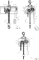
- Fig. 1 1 shows a hoist system 10 according to a first embodiment of the invention.
- the hoist system includes a chain drive system with a double chain 11 and a double sprocket 12 according to the invention, as discussed in detail below, as well as an electrically driven motor 13, which, via a gear 14, drives the shaft 15 for driving the chain drive system 11, i.e., the shaft on which the double sprocket of the chain drive system 11 is arranged.
- a connecting cable 19 serves to supply electricity to the electric motor 13.
- the motor 13, the gearbox 14, and the upper part of the chain drive system 11 are housed in a housing 16, which is open at the bottom, at least in the area of the chain drive.
- the housing 16 can be held and positioned on its upper side, for example, by means of a mounting hook 17 permanently mounted thereon on a support or crane boom (not shown).
- the lifting system 10, and in particular the operation of the electric motor 13, are controlled and monitored in a conventional manner, e.g., via a manual control unit 18.
- Fig. 3 is a perspective view of an embodiment of a chain drive system K, which is used in particular as a chain drive system 11 in the system of Fig. 1
- the chain drive system K contains a chain drive in the form of a double chain wheel D1 together with two chain strands S11, S12 of a chain hoist guided on it, at the ends of which a stop device A1 is also attached.
- the two chain strands S11, S12 are each guided around one of the two chain wheels R11, R12 of the double chain wheel D1, with the individual chain links being held and guided alternately in a vertical position T and in a horizontal position L on the respective chain wheel R11, R12.
- a conventional lifting system 20 with a single chain 21 and a chain wheel 22 is shown. Since in this case the load to be lifted is held and moved by a single chain, the chain 21 is dimensioned accordingly; the dimensioning of the motor 23 and gearbox 24 follow the dimensioning of the chain 21.
- the two chains 11 of the lifting system 10 of the Fig. 1 can be designed smaller, since the load to be lifted is distributed across two chain strands. This also allows for a smaller design of the gearbox 14 and possibly also of the motor 13. This results in an overall smaller and more economical design of the lifting mechanism system 10, with less space required - smaller housing 16 - and a lower weight of the lifting mechanism compared to previous lifting mechanisms.
- the multiple chain design results in increased safety against chain strand breakage due to the redundancy of the chain strands.
- Fig. 4 shows further details of the sprockets of the chain drive (double sprocket D1) of the Fig. 3 without inserted chain links.
- Fig. 4a a front view
- Fig. 4b shows a longitudinal sectional view along a cutting plane through the rotation axis d of the chain drive
- Fig. 4c shows a sectional view of a sprocket R11 along the median plane m1 (viewing direction along the axis of rotation d); this corresponds entirely to a sectional view of the other sprocket R12 along the median plane m2.
- Fig. 5 The chain drive system K is shown in three further views ( Fig. 5a-5c ), namely in a top view ( Fig. 5a ; View along the load direction b), a front view ( Fig. 5b ) and a side view ( Fig. 5c ; Viewing direction parallel to the rotation axis d of the chain wheel).
- Fig. 3 to 5 The chain drive is shown without the housing so that the chain wheel and the chain strands guided in it are more clearly visible; the housing E1 is optional and is described below using the Fig. 6 explained.
- Each of the sprockets R11 and R12 is designed as a so-called pocket sprocket. It therefore has pockets H that are adapted to the oval link shape and that provide a substantially flat support surface (pocket bottom) for each horizontal chain link L (cf. Fig. 5a ). In the longitudinal center of the pockets, recesses can also be formed if necessary, which serve to prevent any Weld bead (not shown) to accommodate one leg of the chain link, so that a horizontal chain link L can rest flat on the support surface of the pocket H even in the presence of such a weld bead.
- the pockets of the sprocket are delimited from one another by webs G, with each web being divided by a groove F for receiving the vertical links T in the center plane m1, m2 of the sprocket R11, R12, so that a web G is divided into two teeth Z (to the left and right of the center plane m1 and m2 respectively).
- the webs G have convex flanks, which at their "inner” edge (i.e., closest to the rotation axis d) merge directly into the flat support surfaces of the pockets H, preferably with a pronounced transition edge.
- a recess can also be provided between the teeth Z. This recess serves the same purpose as the above-mentioned recess in the pocket bottom, namely to accommodate any welding bead (not shown) of the vertical link T, so that the latter can rest or be supported flatly on the groove bottom with the flat outer side of its inner leg.
- both the horizontal links L and the vertical links T are supported flatly, namely the horizontal links L with a large part of their side surfaces on the support surface of the pockets and the vertical links T with the outer surface of the inner leg on the groove bottom.
- the two sprockets R11, R12 are connected coaxially and rotationally fixed to one another.
- the sprockets are arranged with respect to one another without any relative angular offset, i.e. the chain pockets of one sprocket R11 are located directly next to the chain pockets of the other sprocket R12, viewed along the rotation axis d.
- This can also be applied to the webs G, i.e. the webs G of one sprocket R11 are located directly next to the webs G of the other sprocket R12, viewed along the rotation axis d.
- the two sprockets R11, R12 can also be considered as being symmetrical to each other around the center plane m0.
- the two sprockets are formed integrally within the double sprocket D1; alternatively, they can be designed as separate components R11 and R12, which are connected to each other in a suitable manner for rotation, e.g., by means of connecting pins or by welding.
- the load (not shown) to be carried by the hoist is connected to the ends of the two chains S11, S12 by means of a sling device A1, each of which has a connection point for the chain strands, these connection points being arranged at the same height along the load direction.
- the sling device A1 comprises a sling component C1 with a load hook B1.
- the sling component C1 is formed by a bush-like body with connection points C11, C12 provided in its "upper" area. Using these connection points C11, C12, which are provided inside the body, the respective end links of the chain strands are inserted and fastened, for example, with a bolt (not shown).
- the load hook B1 is mounted in the "underside" of the body of the stop component C1, preferably rotatable about an axis parallel to the load direction b. In one variant, however, the load hook B1 can be attached to the body of the stop component C1 in a rotationally fixed manner.
- the stop device has, on the side opposite the connecting part, two (or possibly more) connection points arranged next to one another for one end link of each link chain, wherein these connection points are preferably arranged at the same height as seen in the direction of the load.
- Fig. 6 shows an example of a lifting mechanism arrangement W2 in which the double chain wheel D1 is rotatably mounted in a chain drive housing E1 (the components for holding the housing are shown in Fig. 6 omitted for clarity).
- Fig. 6a a front view
- Fig. 6b shows a longitudinal sectional view along a "horizontal" section plane 6-6 through the rotation axis d of the double chain wheel D1
- Fig. 6c shows a sectional view along the center plane m1 of the sprocket R11.
- the housing E1 surrounds the sprockets R11, R12 and limits the radial movement of the link chains on the sprockets.
- the double sprocket D1 is fixed to the housing E1 by the shaft (which runs along the rotational axis d) and its mountings (not shown). concentrically mounted so that the wheel D1 can rotate in the housing E1 without touching it and at the same time is rotatably held therein.
- the housing has two grooves F1, F2 on the inside, side by side, in which stationary links of the link chains running on the sprockets are guided.
- An inner part J2 also referred to as a wiper, can also be provided, which closes off the chain drive on the output side and can also guide the chain sections as they enter the chain drive and, in particular, as they detach ("strip") the chains from the sprockets and exit the chain drive.
- the housing E1 and the inner part J2 are held, for example, in the motor housing.
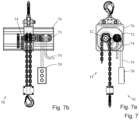
- FIG. 7 represents a pneumatically operated lifting system 70.
- This lifting system 70 also includes a chain drive system with a double chain 11 and a double chain wheel 12 according to the invention, but a motor 73 driven by compressed air, which is controlled and monitored, for example, by a manual operating unit 78 and is pneumatically supplied via a compressed air line 79.
- the pneumatic embodiment is characterized by additional space and weight savings of the motor 73 and gear 74, so that the housing 76 is also even more compact. Otherwise, this embodiment corresponds to the one described above with reference to the Fig. 1 and 3-6 explained embodiment.
Landscapes
- Engineering & Computer Science (AREA)
- Mechanical Engineering (AREA)
- Devices For Conveying Motion By Means Of Endless Flexible Members (AREA)
Priority Applications (3)
| Application Number | Priority Date | Filing Date | Title |
|---|---|---|---|
| EP23208259.4A EP4553032B1 (fr) | 2023-11-07 | 2023-11-07 | Dispositif d'entraînement à chaîne et élévateur à pignon à chaîne double |
| US18/928,250 US20250145429A1 (en) | 2023-11-07 | 2024-10-28 | Chain drive arrangement and lifting equipment with double chain wheel |
| JP2024193522A JP2025078069A (ja) | 2023-11-07 | 2024-11-05 | ダブルチェーンホイールを伴うチェーン駆動装置及び昇降設備 |
Applications Claiming Priority (1)
| Application Number | Priority Date | Filing Date | Title |
|---|---|---|---|
| EP23208259.4A EP4553032B1 (fr) | 2023-11-07 | 2023-11-07 | Dispositif d'entraînement à chaîne et élévateur à pignon à chaîne double |
Publications (3)
| Publication Number | Publication Date |
|---|---|
| EP4553032A1 true EP4553032A1 (fr) | 2025-05-14 |
| EP4553032C0 EP4553032C0 (fr) | 2025-10-08 |
| EP4553032B1 EP4553032B1 (fr) | 2025-10-08 |
Family
ID=88731340
Family Applications (1)
| Application Number | Title | Priority Date | Filing Date |
|---|---|---|---|
| EP23208259.4A Active EP4553032B1 (fr) | 2023-11-07 | 2023-11-07 | Dispositif d'entraînement à chaîne et élévateur à pignon à chaîne double |
Country Status (3)
| Country | Link |
|---|---|
| US (1) | US20250145429A1 (fr) |
| EP (1) | EP4553032B1 (fr) |
| JP (1) | JP2025078069A (fr) |
Citations (7)
| Publication number | Priority date | Publication date | Assignee | Title |
|---|---|---|---|---|
| GB716999A (en) * | 1952-03-28 | 1954-10-20 | Maby & Co | Improvements in chain hoists |
| DE20305256U1 (de) * | 2002-12-13 | 2003-06-18 | Iseken, Detlef, 33154 Salzkotten | Motorgetriebener Kettenzug |
| AU2004233530A1 (en) * | 2004-01-19 | 2005-08-04 | Caterpillar Global Mining Europe Gmbh | Sprocket wheel for underground mining |
| US10882724B1 (en) * | 2020-08-10 | 2021-01-05 | Wired Specialty Equipment, LLC | Redundant multi-point chain hoist apparatus |
| US10900559B2 (en) * | 2018-05-31 | 2021-01-26 | James Zaguroli, Jr. | Automatic lubrication arrangement for a hoist |
| CN113428795A (zh) * | 2021-07-22 | 2021-09-24 | 北京金炫业科技有限公司 | 一种链式液压葫芦 |
| EP4155252A1 (fr) * | 2021-09-23 | 2023-03-29 | Pewag Austria GmbH | Transmission par chaîne pourvue de roue à double chaîne, dispositif de butée associé, ainsi que système de transmission par chaîne |
-
2023
- 2023-11-07 EP EP23208259.4A patent/EP4553032B1/fr active Active
-
2024
- 2024-10-28 US US18/928,250 patent/US20250145429A1/en active Pending
- 2024-11-05 JP JP2024193522A patent/JP2025078069A/ja active Pending
Patent Citations (7)
| Publication number | Priority date | Publication date | Assignee | Title |
|---|---|---|---|---|
| GB716999A (en) * | 1952-03-28 | 1954-10-20 | Maby & Co | Improvements in chain hoists |
| DE20305256U1 (de) * | 2002-12-13 | 2003-06-18 | Iseken, Detlef, 33154 Salzkotten | Motorgetriebener Kettenzug |
| AU2004233530A1 (en) * | 2004-01-19 | 2005-08-04 | Caterpillar Global Mining Europe Gmbh | Sprocket wheel for underground mining |
| US10900559B2 (en) * | 2018-05-31 | 2021-01-26 | James Zaguroli, Jr. | Automatic lubrication arrangement for a hoist |
| US10882724B1 (en) * | 2020-08-10 | 2021-01-05 | Wired Specialty Equipment, LLC | Redundant multi-point chain hoist apparatus |
| CN113428795A (zh) * | 2021-07-22 | 2021-09-24 | 北京金炫业科技有限公司 | 一种链式液压葫芦 |
| EP4155252A1 (fr) * | 2021-09-23 | 2023-03-29 | Pewag Austria GmbH | Transmission par chaîne pourvue de roue à double chaîne, dispositif de butée associé, ainsi que système de transmission par chaîne |
Also Published As
| Publication number | Publication date |
|---|---|
| EP4553032C0 (fr) | 2025-10-08 |
| JP2025078069A (ja) | 2025-05-19 |
| US20250145429A1 (en) | 2025-05-08 |
| EP4553032B1 (fr) | 2025-10-08 |
Similar Documents
| Publication | Publication Date | Title |
|---|---|---|
| EP2565148B1 (fr) | Transstockeur avec chariot de levage entraîné par un sytème de mouflage | |
| EP2047141B1 (fr) | Pignon à chaîne, à force portante élevée | |
| AT501098A1 (de) | Lasthebevorrichtung | |
| EP2047142B1 (fr) | Poulie de renvoi avec meilleure utilisation de la chaine | |
| EP2912343B1 (fr) | Chaîne articulée et mécanisme d'entraînement d'une chaîne articulée, en particulier pour une construction hydraulique en acier et un élévateur à godets sur chaîne | |
| EP4553032B1 (fr) | Dispositif d'entraînement à chaîne et élévateur à pignon à chaîne double | |
| EP3015414B1 (fr) | Moyen de suspension de charge | |
| EP4155252B1 (fr) | Transmission par chaîne pourvue de roue à double chaîne, dispositif de butée associé, ainsi que système de transmission par chaîne | |
| EP1572495A1 (fr) | Vehicule d'aire de stationnement pourvu d'un dispositif d'entrainement a vis sans fin | |
| DE102004021708B4 (de) | Vereinfachte Katze mit niedriger Bauhöhe | |
| EP1273549B1 (fr) | Dispositif de levage | |
| EP3428115A1 (fr) | Dispositif de levage et procédé de déplacement d'un chariot élévateur | |
| DE29519208U1 (de) | Verfahrbare Lasthebevorrichtung | |
| DE20302374U1 (de) | Scherenhubtisch | |
| EP4182257B1 (fr) | Dispositif de levage pour lever et abaisser des charges | |
| EP3290381A1 (fr) | Systeme d'entrainement a faible encombrement pour un escalier ou un trottoir | |
| DE756899C (de) | UEber Ketten, Riemen, Seile od. dgl. Zuguebertragungsorgane gleichzeitig zweiseitig angetriebene Einrichtungen, insbesondere Becherwerke und Kettenbahnen | |
| DE3017969C2 (de) | Einrichtung zur Parallelführung der Spanntrommel eines Senkrechtsförderers | |
| DE102004034589B3 (de) | Kettenzug | |
| WO2018172361A1 (fr) | Entraînement de chaîne articulée, en particulier pour un escalier roulant | |
| DE19832637A1 (de) | Raupenfahrwerk | |
| DE964398C (de) | Umkehrstation fuer Doppelketten-Kratzfoerderer | |
| DE1556173B2 (de) | Kettenfoerderer mit rundstahlketten | |
| EP0509404A2 (fr) | Installation de transport sur tractions par câble pour actionner des câbles | |
| DE2729724A1 (de) | Foerdervorrichtung |
Legal Events
| Date | Code | Title | Description |
|---|---|---|---|
| PUAI | Public reference made under article 153(3) epc to a published international application that has entered the european phase |
Free format text: ORIGINAL CODE: 0009012 |
|
| STAA | Information on the status of an ep patent application or granted ep patent |
Free format text: STATUS: REQUEST FOR EXAMINATION WAS MADE |
|
| 17P | Request for examination filed |
Effective date: 20241127 |
|
| AK | Designated contracting states |
Kind code of ref document: A1 Designated state(s): AL AT BE BG CH CY CZ DE DK EE ES FI FR GB GR HR HU IE IS IT LI LT LU LV MC ME MK MT NL NO PL PT RO RS SE SI SK SM TR |
|
| GRAP | Despatch of communication of intention to grant a patent |
Free format text: ORIGINAL CODE: EPIDOSNIGR1 |
|
| STAA | Information on the status of an ep patent application or granted ep patent |
Free format text: STATUS: GRANT OF PATENT IS INTENDED |
|
| GRAS | Grant fee paid |
Free format text: ORIGINAL CODE: EPIDOSNIGR3 |
|
| GRAA | (expected) grant |
Free format text: ORIGINAL CODE: 0009210 |
|
| STAA | Information on the status of an ep patent application or granted ep patent |
Free format text: STATUS: THE PATENT HAS BEEN GRANTED |
|
| INTG | Intention to grant announced |
Effective date: 20250821 |
|
| AK | Designated contracting states |
Kind code of ref document: B1 Designated state(s): AL AT BE BG CH CY CZ DE DK EE ES FI FR GB GR HR HU IE IS IT LI LT LU LV MC ME MK MT NL NO PL PT RO RS SE SI SK SM TR |
|
| REG | Reference to a national code |
Ref country code: GB Ref legal event code: FG4D Free format text: NOT ENGLISH Ref country code: CH Ref legal event code: F10 Free format text: ST27 STATUS EVENT CODE: U-0-0-F10-F00 (AS PROVIDED BY THE NATIONAL OFFICE) Effective date: 20251008 |
|
| REG | Reference to a national code |
Ref country code: DE Ref legal event code: R096 Ref document number: 502023001945 Country of ref document: DE |
|
| REG | Reference to a national code |
Ref country code: IE Ref legal event code: FG4D Free format text: LANGUAGE OF EP DOCUMENT: GERMAN |
|
| U01 | Request for unitary effect filed |
Effective date: 20251010 |
|
| U07 | Unitary effect registered |
Designated state(s): AT BE BG DE DK EE FI FR IT LT LU LV MT NL PT RO SE SI Effective date: 20251017 |
|
| U20 | Renewal fee for the european patent with unitary effect paid |
Year of fee payment: 3 Effective date: 20251230 |
|
| PG25 | Lapsed in a contracting state [announced via postgrant information from national office to epo] |
Ref country code: ES Free format text: LAPSE BECAUSE OF FAILURE TO SUBMIT A TRANSLATION OF THE DESCRIPTION OR TO PAY THE FEE WITHIN THE PRESCRIBED TIME-LIMIT Effective date: 20251008 |
|
| PG25 | Lapsed in a contracting state [announced via postgrant information from national office to epo] |
Ref country code: NO Free format text: LAPSE BECAUSE OF FAILURE TO SUBMIT A TRANSLATION OF THE DESCRIPTION OR TO PAY THE FEE WITHIN THE PRESCRIBED TIME-LIMIT Effective date: 20260108 |
|
| PG25 | Lapsed in a contracting state [announced via postgrant information from national office to epo] |
Ref country code: HR Free format text: LAPSE BECAUSE OF FAILURE TO SUBMIT A TRANSLATION OF THE DESCRIPTION OR TO PAY THE FEE WITHIN THE PRESCRIBED TIME-LIMIT Effective date: 20251008 |
|
| PG25 | Lapsed in a contracting state [announced via postgrant information from national office to epo] |
Ref country code: RS Free format text: LAPSE BECAUSE OF FAILURE TO SUBMIT A TRANSLATION OF THE DESCRIPTION OR TO PAY THE FEE WITHIN THE PRESCRIBED TIME-LIMIT Effective date: 20260108 |
|
| PG25 | Lapsed in a contracting state [announced via postgrant information from national office to epo] |
Ref country code: IS Free format text: LAPSE BECAUSE OF FAILURE TO SUBMIT A TRANSLATION OF THE DESCRIPTION OR TO PAY THE FEE WITHIN THE PRESCRIBED TIME-LIMIT Effective date: 20260208 |
|
| PG25 | Lapsed in a contracting state [announced via postgrant information from national office to epo] |
Ref country code: PL Free format text: LAPSE BECAUSE OF FAILURE TO SUBMIT A TRANSLATION OF THE DESCRIPTION OR TO PAY THE FEE WITHIN THE PRESCRIBED TIME-LIMIT Effective date: 20251008 |