EP4553036A1 - Procédé et installation pour le traitement de boîtes - Google Patents
Procédé et installation pour le traitement de boîtes Download PDFInfo
- Publication number
- EP4553036A1 EP4553036A1 EP24211387.6A EP24211387A EP4553036A1 EP 4553036 A1 EP4553036 A1 EP 4553036A1 EP 24211387 A EP24211387 A EP 24211387A EP 4553036 A1 EP4553036 A1 EP 4553036A1
- Authority
- EP
- European Patent Office
- Prior art keywords
- sterilization
- nozzle
- filling
- sterilization medium
- cans
- Prior art date
- Legal status (The legal status is an assumption and is not a legal conclusion. Google has not performed a legal analysis and makes no representation as to the accuracy of the status listed.)
- Pending
Links
Images
Classifications
-
- B—PERFORMING OPERATIONS; TRANSPORTING
- B67—OPENING, CLOSING OR CLEANING BOTTLES, JARS OR SIMILAR CONTAINERS; LIQUID HANDLING
- B67C—CLEANING, FILLING WITH LIQUIDS OR SEMILIQUIDS, OR EMPTYING, OF BOTTLES, JARS, CANS, CASKS, BARRELS, OR SIMILAR CONTAINERS, NOT OTHERWISE PROVIDED FOR; FUNNELS
- B67C7/00—Concurrent cleaning, filling, and closing of bottles; Processes or devices for at least two of these operations
- B67C7/0073—Sterilising, aseptic filling and closing
-
- B—PERFORMING OPERATIONS; TRANSPORTING
- B65—CONVEYING; PACKING; STORING; HANDLING THIN OR FILAMENTARY MATERIAL
- B65B—MACHINES, APPARATUS OR DEVICES FOR, OR METHODS OF, PACKAGING ARTICLES OR MATERIALS; UNPACKING
- B65B55/00—Preserving, protecting or purifying packages or package contents in association with packaging
- B65B55/02—Sterilising, e.g. of complete packages
- B65B55/04—Sterilising wrappers or receptacles prior to, or during, packaging
- B65B55/10—Sterilising wrappers or receptacles prior to, or during, packaging by liquids or gases
-
- A—HUMAN NECESSITIES
- A61—MEDICAL OR VETERINARY SCIENCE; HYGIENE
- A61L—METHODS OR APPARATUS FOR STERILISING MATERIALS OR OBJECTS IN GENERAL; DISINFECTION, STERILISATION OR DEODORISATION OF AIR; CHEMICAL ASPECTS OF BANDAGES, DRESSINGS, ABSORBENT PADS OR SURGICAL ARTICLES; MATERIALS FOR BANDAGES, DRESSINGS, ABSORBENT PADS OR SURGICAL ARTICLES
- A61L2/00—Disinfection or sterilisation of materials or objects, in general; Accessories therefor
- A61L2/16—Disinfection or sterilisation of materials or objects, in general; Accessories therefor using chemical substances
- A61L2/20—Gaseous substances, e.g. vapours
- A61L2/208—Hydrogen peroxide
-
- A—HUMAN NECESSITIES
- A61—MEDICAL OR VETERINARY SCIENCE; HYGIENE
- A61L—METHODS OR APPARATUS FOR STERILISING MATERIALS OR OBJECTS IN GENERAL; DISINFECTION, STERILISATION OR DEODORISATION OF AIR; CHEMICAL ASPECTS OF BANDAGES, DRESSINGS, ABSORBENT PADS OR SURGICAL ARTICLES; MATERIALS FOR BANDAGES, DRESSINGS, ABSORBENT PADS OR SURGICAL ARTICLES
- A61L2103/00—Materials or objects being the target of disinfection or sterilisation
- A61L2103/23—Containers other than laboratory or medical, e.g. bottles or mail
-
- B—PERFORMING OPERATIONS; TRANSPORTING
- B67—OPENING, CLOSING OR CLEANING BOTTLES, JARS OR SIMILAR CONTAINERS; LIQUID HANDLING
- B67C—CLEANING, FILLING WITH LIQUIDS OR SEMILIQUIDS, OR EMPTYING, OF BOTTLES, JARS, CANS, CASKS, BARRELS, OR SIMILAR CONTAINERS, NOT OTHERWISE PROVIDED FOR; FUNNELS
- B67C3/00—Bottling liquids or semiliquids; Filling jars or cans with liquids or semiliquids using bottling or like apparatus; Filling casks or barrels with liquids or semiliquids
- B67C3/02—Bottling liquids or semiliquids; Filling jars or cans with liquids or semiliquids using bottling or like apparatus
- B67C3/22—Details
- B67C2003/228—Aseptic features
-
- B—PERFORMING OPERATIONS; TRANSPORTING
- B67—OPENING, CLOSING OR CLEANING BOTTLES, JARS OR SIMILAR CONTAINERS; LIQUID HANDLING
- B67C—CLEANING, FILLING WITH LIQUIDS OR SEMILIQUIDS, OR EMPTYING, OF BOTTLES, JARS, CANS, CASKS, BARRELS, OR SIMILAR CONTAINERS, NOT OTHERWISE PROVIDED FOR; FUNNELS
- B67C3/00—Bottling liquids or semiliquids; Filling jars or cans with liquids or semiliquids using bottling or like apparatus; Filling casks or barrels with liquids or semiliquids
- B67C3/02—Bottling liquids or semiliquids; Filling jars or cans with liquids or semiliquids using bottling or like apparatus
- B67C3/22—Details
- B67C3/26—Filling-heads; Means for engaging filling-heads with bottle necks
- B67C2003/2657—Filling-heads; Means for engaging filling-heads with bottle necks specially adapted for filling cans
Definitions
- the invention relates to a method for treating cans by internally sterilizing the cans.
- the invention further relates to a can treatment system with a sterilization device.
- filled and sealed beverage cans can be thermally treated in a pasteurizer. This ensures the microbiological safety of the contents, thus protecting the consumer and extending the shelf life of the contents.
- a disadvantage of pasteurization is that, although it is very safe, it is very energy-intensive. Furthermore, the contents of the can can be subjected to significant thermal stress during pasteurization. This can negatively impact the flavor of the contents. Valuable ingredients such as vitamins can also be damaged during the thermal pasteurization process.
- the invention is based on the object of providing an improved technique for treating cans, which is preferably faster, more effective and/or more efficient than the conventional technique, e.g. with a pasteurizing device.
- One aspect of the present disclosure relates to a method for treating cans (e.g., beverage cans or food cans) in a can treatment plant.
- the method comprises supplying (e.g., blowing or injecting) a sterilization medium, preferably comprising Hydrogen peroxide, into a can by means of a sterilization device.
- the method comprises internally sterilizing the can by means of the supplied sterilization medium while the can is transported to a filling station (e.g., a can filling device, e.g., a can filler carousel) (and preferably reaches the filling station).
- a filling station e.g., a can filling device, e.g., a can filler carousel
- the method comprises rinsing the can in the filling station with a purge gas, preferably carbon dioxide, whereby the sterilization medium is (e.g., completely) flushed out of the can.
- the method comprises filling the rinsed can in the filling station with a (e.g., liquid or pasty) filling material.
- the method does not simply allow for sterilization of the cans prior to filling.
- the method advantageously allows for the steps of removing (blowing out) the sterilization medium from the cans and rinsing the cans prior to filling to be integrated or carried out jointly.
- the rinsing performed before filling a can e.g., with CO2
- to reduce the oxygen content in the can is (also) used to rinse the sterilization medium from the can, thereby eliminating the need for a separate step for removing the sterilization medium in the sterilization device.
- both air with the oxygen it contains and the sterilization medium can be rinsed from the can.
- the process can be advantageously particularly fast, as a separate, several-second blow-out time before the can filling device or filling station can be eliminated. Depending on the machine's performance, several meters of transport distance can be saved.
- the transport time to the can filling device and the process time in the filling station up to rinsing represent additional exposure times for the sterilization medium. This also advantageously shortens the exposure time and thus the transport time in the sterilization device, allowing the sterilization device to be designed comparatively small.
- the process can be particularly effective because a comparatively long exposure time is available for internal sterilization.
- the sterilization medium acts against microorganisms within the can for a long time (from addition to complete rinsing).
- the extended exposure time makes the process particularly safe and effective. Due to the long exposure time, a comparatively low concentration of the sterilization medium and/or a reduced amount of the sterilization medium can be used for internal sterilization of the cans.
- special measures to increase the effectiveness of the Sterilization medium can be dispensed with, such as temperature activation and/or condensation of the sterilization medium on the inside of the container.
- the process can be particularly energy-efficient, for example, because it saves media.
- the rinsing can be carried out indirectly or immediately before filling or immediately before pre-tensioning the can in the filling station before filling.
- the sterilization medium is gaseous or substantially gaseous during supply and/or internal sterilization.
- the supplied sterilization medium can be supplied in such a way that it does not condense in the container and/or that it retains its gaseous state in the container.
- the comparatively long exposure time of the sterilization medium can eliminate the need for complex processing technology for activating and/or condensing the sterilization medium.
- the supplied sterilization medium remains essentially in the container until rinsing. This advantageously allows for particularly effective internal sterilization of the container.
- the can is transported linearly and/or upright through the sterilization device during the supply of the sterilization medium.
- the can can be transported upright to the filling station during internal sterilization (e.g., using a can conveyor). This advantageously ensures that as little sterilization medium as possible escapes from the can.
- the purge gas is supplied to the filling station via a preferably central purge gas supply channel during purging.
- the sterilization medium is purged into a preferably annular purge gas discharge channel of the filling station during purging.
- the method further comprises sucking the sterilization medium out of the can in the filling station, preferably when rinsing the can in the filling station.
- the sterilization medium is supplied via at least one nozzle of the sterilization device. This advantageously allows for precise delivery of the sterilization medium into the container.
- the at least one nozzle comprises at least one stationary nozzle, and the can moves past the at least one stationary nozzle during the supply of the sterilization medium. This advantageously enables a structurally simple design of the sterilization device.
- the at least one nozzle comprises at least one movable nozzle.
- the at least one movable nozzle can move with the can during the supply of the sterilization medium. This can advantageously support a particularly reliable and sufficient filling of the cans with the sterilization medium.
- the at least one movable nozzle can advantageously ensure that, depending on the geometry of the can, even hard-to-reach areas of the can can be reached by the sterilization medium.
- the amount of sterilization medium discharged from the at least one nozzle is constant. This advantageously minimizes the effort required to control the sterilization device.
- the amount of sterilization medium discharged from the at least one nozzle can be adjusted depending on the transport speed of the can along the at least one nozzle (e.g., automatically by a control device). This advantageously allows sufficient filling of the can with the sterilization medium while simultaneously saving sterilization medium.
- control device can refer to electronics (e.g., implemented as a driver circuit or with microprocessor(s) and data memory) and/or a mechanical, pneumatic, and/or hydraulic control system, which, depending on its design, can perform control tasks and/or regulation tasks and/or processing tasks. Even if the term “control” is used herein, it can also appropriately include or mean “regulation” or “control with feedback” and/or “processing.”
- This also advantageously allows sufficient filling of the container with the sterilization medium while simultaneously saving sterilization medium.
- the method further comprises sterilizing at least one section of the filling station using the sterilization medium flushed out of the can (e.g., directly during rinsing from the container), wherein the at least one section preferably has a filling material outlet of the filling station and/or a sealing surface of the filling station.
- the sterilization medium can thus be used in two ways: primarily for internal sterilization of the container and secondarily for sterilizing parts of the filling station during rinsing from the container.
- the filled can is not pasteurized in the can treatment plant.
- a further aspect of the present disclosure relates to a can processing plant, which is preferably designed to carry out a method as disclosed herein.
- the can processing plant comprises a sterilization device configured to supply a preferably gaseous sterilization medium, preferably comprising hydrogen peroxide, into cans.
- the can treatment system comprises a can filling device (e.g., a can filling carousel) arranged downstream of the sterilization device and having at least one filling station configured to rinse the cans, to flush the sterilization medium out of the cans, and to fill the cans with a filling material.
- the can treatment system can achieve the same advantages as those already explained with reference to the method.
- the can processing system further comprises a can conveyor that directly connects the sterilization device to the can filling device.
- the can processing system may be free of a pasteurization device for pasteurizing the cans after filling.
- the can processing system may not comprise any device configured to remove the sterilization medium from the cans from the beginning of the sterilization device to the can filling device.
- the sterilization device may comprise at least one nozzle for supplying the sterilization medium to the cans.
- the at least one nozzle may comprise at least one stationary nozzle and/or at least one movable nozzle.
- the sterilization device may include a can conveyor for transporting the cans while the sterilization medium is being supplied to the cans.
- the can conveyor is preferably configured to transport the cans upright and/or linearly through the sterilization device.
- the sterilization device may comprise a housing (e.g. tunnel-shaped or block-shaped) in which the at least one nozzle and/or the can conveyor are arranged.
- a housing e.g. tunnel-shaped or block-shaped
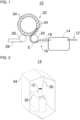
- the Figure 1 shows a can processing system 10, i.e., a system 10 for processing cans 12.
- the cans 12 can be, for example, beverage cans or food cans.
- the can processing system 10 can be designed as a can filling system.
- the cans 12 are handled and transported in the can processing system 10 using so-called base handling.
- the can processing system 10 includes a sterilization device 14 and a can filling device 22 with at least one filling station 24.
- the sterilization device 14 can also be referred to as a disinfection device.
- the can processing system 10 can further include a can conveyor 16.
- the sterilization device 14 introduces or supplies a sterilization medium into the cans 12.
- the sterilization device 14 can inject the sterilization medium into the cans 12.
- the sterilization medium can also be referred to as a disinfection medium.
- the sterilization medium supplied by the sterilization device 14 is preferably gaseous or at least substantially gaseous.
- the supplied sterilization medium can fill the cans 12.
- the sterilization medium can remain in the cans 12, for example, due to gravity and due to an upright orientation of the cans 12.
- the supplied sterilization medium can preferably be supplied by the sterilization device 14 in such a way that it does not condense in the can 12 and that it maintains its (essentially) gaseous state in the can 12.
- the cans 12 can have a temperature corresponding to the ambient temperature before, during, and/or after supply. It is possible for the sterilization medium to be supplied to the can 12 at a temperature that prevents condensation of the sterilization medium in the can 12 and/or supports maintenance of the (essentially) gaseous state of the sterilization medium in the can 12. It is also possible for the cans 12 and/or the sterilization medium to be preheated, for example, before the sterilization medium is supplied and/or reheated after the sterilization medium is supplied.
- the sterilization medium can preferably be or comprise hydrogen peroxide.
- the sterilization medium is preferably vaporized before being supplied.
- the sterilization medium can, for example, be supplied to the cans 12 as a mixture with air.
- the supplied sterilization medium sterilizes the cans 12 internally while the cans 12 are transported to the filling stations 24.
- the sterilization medium remains gaseous or at least substantially gaseous during internal sterilization.
- the cans 12 can be transported directly or via the can conveyor 16 to the filling stations 24.
- the cans 12 can preferably be transported upright from the sterilization device 14 to the respective filling station 24.
- the can treatment system 10 does not have a device designed to remove the sterilization medium from the cans 12 with respect to a can flow through the can treatment system 10 from the beginning of the sterilization device 14 up to the can filling device 22.
- the supplied sterilization medium can internally sterilize the cans 12 during transport along an exposure path E.
- the exposure path E can extend, for example, from a position in the sterilization device 14 at which the sterilization medium is supplied to the respective can 12.
- the exposure path E can extend to the respective filling station 24 at a position at which the respective filling station 24 begins to flush the respective can 12 with a flushing gas.
- the sterilization medium can essentially remain and act in the can 12.
- the can conveyor 16 may directly connect the sterilization device 14 to the can filling device 22.
- the can conveyor 16 may be located directly downstream of the sterilization device 14 with respect to a can flow through the can processing system 10.
- the can conveyor 16 may be located directly upstream of the can filling device 22 with respect to a can flow through the can processing system 10.
- the can conveyor 16 can transport the cans 12 preferably in an upright position, for example in base handling.
- the can conveyor 16 can, for example, have a linear conveyor 18 and/or an infeed starwheel 20.
- the linear conveyor 18 can receive the cans 12 from the sterilization device 14 and transfer them to the infeed starwheel 20.
- the infeed starwheel 20 can transfer the cans 12 one after the other to the filling stations 24.
- the infeed starwheel 20 can, for example, receive the cans directly from the sterilization device 14 or from the linear conveyor 18.
- the can filling device 22 is arranged downstream (in terms of cans) of the sterilization device 14 with respect to a can flow through the can processing system 10.
- the can filling device 22 can be arranged directly downstream of the sterilization device 14.
- the can filling device 22 can be arranged, for example, directly downstream of the can conveyor 16, which in turn can be arranged directly downstream of the sterilization device 14.
- the can filling device 22 preferably has a plurality of filling stations 24.
- one can 12 can be processed in each of the multiple filling stations 24.
- a plurality of the cans 12 can be processed simultaneously or at least in a temporally overlapping manner in the multiple filling stations 24.
- the can filling device 22 can be designed as a can filling carousel or a rotary can filler.
- the filling stations 24 can be arranged distributed around a circumference of the can filling device 22.
- the can filling device 22 it is also possible for the can filling device 22 to be, for example, a linear can filler with several filling stations arranged in series one behind the other and/or next to each other (not shown). Figure 1 shown).
- the filling station 24 is designed to rinse a respective can 12 to flush the sterilization medium out of the can 12. Rinsing can be performed, for example, immediately before filling or immediately before pre-pressurization prior to filling.
- the filling station 24 flushes the respective can 12 with a flushing gas, whereby the sterilization medium is flushed out of the can 12 after the internal sterilization of the can 12.
- oxygen can also be flushed out of the can 12.
- the flushing gas is preferably a process gas of the can filling device 22.
- the flushing gas is carbon dioxide.
- the rinsing of the can 12, i.e. the rinsing out of the sterilization medium and possibly oxygen during rinsing, in the filling station 24 is additionally supported by suctioning off the sterilization medium by means of the filling station 24.
- the sterilization medium flushed out of the can 12 can sterilize at least one area of the filling station 24 as it flows out of the can 12.
- the sterilization medium can pass through a filling material outlet of the filling station 24 and/or sealing surfaces of the filling station 24 and thereby sterilize them.
- the rinsed sterilization medium can be collected and reused, e.g., by the sterilization device 14.
- the filling station 24 is also designed to fill the cans 12 with a filling material.
- the filling station 24 fills the respective can 12 after rinsing, for example, immediately after rinsing or after pre-pressurizing the can 12.
- the filling material is preferably a liquid or pasty filling material, for example, a beverage or a food product.
- the filling station 24 can, for example, be an aseptic filling station for aseptically filling the cans 12 with the filling material.
- the filling station 24 can also evacuate the respective can 12, e.g., before or after rinsing, and/or pre-tension it, e.g., after rinsing.
- the cans 12 can be transported, for example, to a closing device (not in Figure 1
- the closing device can close the filled cans 12 with a can lid.
- the closing device can, for example, have at least one closing head for closing the cans.
- the closing device can preferably be designed as a closing carousel or a rotary closer.
- the can treatment plant 10 may be free of a pasteurization device for pasteurizing the cans 12 after filling.
- the can processing system 10 can have additional can processing devices, such as a depalletizing device and/or a rinsing device (e.g., with rinsing nozzles), which can be arranged, for example, upstream (in terms of cans) of the sterilization device 14.
- the can processing system 10 can have, for example, the already mentioned closing device, an adhesive pack manufacturing device (e.g., with adhesive application nozzles), a packaging device (e.g., with packing heads or film wrappers), and/or a palletizing device (e.g., with palletizing heads, sliding plates, or the like), which can be arranged, for example, downstream (in terms of cans) of the can filling device 22.
- the can processing plant 10 may have additional can conveyors for transporting the cans 12 through the can processing plant 10.
- the additional can conveyors may comprise at least one transport star and/or at least one linear conveyor.
- an outlet star 26 may receive the cans 12 filled by the can filling device 22 and transfer them to a downstream can conveyor 28, for example, a linear conveyor, for further transport.
- the Figures 2 and 3 show an exemplary embodiment of the sterilization device 14.
- the at least one nozzle 30 can supply the sterilization medium to the cans 12 or introduce/fill it into the cans 12. Preferably, the at least one nozzle 30 does not dip into the respective can 12 when supplying the sterilization medium to the respective can 12.
- the at least one nozzle 30 may comprise at least one stationary nozzle.
- the respective can 12 may move past the stationary nozzle during the supply of the gaseous sterilization medium from the stationary nozzle.
- the at least one nozzle 30 may have at least one movable nozzle.
- the movable nozzle may move with the respective can 12 during the supply of the sterilization medium from the movable nozzle.
- the movable nozzle may, for example, be pivotable to follow the moving respective can 12.
- the movable nozzle may, for example, be displaceable to follow the moving respective can 12.
- the displaceable nozzle may, for example, move back and forth or move along a closed path.
- the sterilization device 14 can have at least one drive, for example, an electric motor, for driving a movement of the movable nozzle. It is possible for the drive for driving the movement of the movable nozzle to be coupled to a drive of the can conveyor 32. It is also possible for the drive for driving the movement of the movable nozzle to also drive the can conveyor 32.
- an electric motor for driving a movement of the movable nozzle.
- the sterilization device 14 may further comprise at least one guide for guiding the movement of the movable nozzle.
- the at least one guide may comprise, for example, a pivoting guide, a linear guide, and/or a track guide.
- the at least one nozzle 30 can, for example, have a nozzle that blows the sterilization medium vertically from above and centrally into the can 12. Additionally or alternatively, the at least one nozzle 30 can, for example, have a nozzle that blows the sterilization medium vertically from above and off-center into the can 12. Additionally or alternatively, the at least one nozzle 30 can, for example, have a nozzle that blows the sterilization medium from above at an angle to a vertical axis of the can 12.
- a sterilization medium jet emanating from the nozzle can preferably be angled to a vertical axis of the can 12 at an angle of between 10° and 20°, particularly preferably approximately 15°.
- the at least one nozzle 30 can, for example, discharge a constant amount of sterilization medium.
- the sterilization medium discharge amount can be adjusted depending on the transport speed of the can 12 or the can conveyor 32 along the at least one nozzle 30, e.g., automatically by a control device.
- the sterilization medium can be delivered in pulsed fashion from the at least one nozzle 30, e.g., with one or more pulses per can 12.
- a pulse frequency can be adapted to a frequency of cans 12 moving past the at least one nozzle 30.
- a pulse duration can be adapted to a transport speed (e.g., of the can conveyor 32) at which the can 12 is moved past the at least one nozzle 30.
- the can conveyor 32 can transport the cans 12 through the sterilization device 14.
- the can conveyor 32 is preferably a linear conveyor.
- the linear conveyor can transport the cans 12 linearly through the sterilization device 14.
- the cans 12 can be transported upright by the can conveyor 32.
- the can conveyor 32 can transport the cans 12, for example, using base handling.
- the can conveyor 32 can be a belt conveyor, a mat chain conveyor, or a plate conveyor.
- the can conveyor 32 can transport the cans 12 through the sterilization device 14, for example, in a single lane, multiple lanes, or in a random mass flow.
- the at least one nozzle 30 and/or the can conveyor 32 can be arranged in the housing 34 of the sterilization device 14.
- the housing 34 can, for example, have a tunnel shape or a block shape.
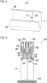
- the Figure 4 shows a portion of an exemplary embodiment of the filling station 24.
- the filling station 24 may, for example, have a filling valve 36, a purge gas supply channel 50, a purge gas discharge channel 54, a seal 60 and/or a can support 62.
- the filling valve 36 can fill the can 12 positioned below the filling valve 36 with the filling material.
- the filling valve 36 can have a movable valve member 38 for opening and closing the filling valve 24.
- the valve member 38 can be movable along a central axis M of the filling valve 36 or the filling station 24.
- the central axis M can be a central longitudinal axis (central vertical axis) of the filling valve 36 or the filling station 24.
- the valve member 38 can be movable relative to a preferably funnel-shaped valve seat 40 of the filling valve 36.
- the valve seat 40 can preferably be a valve cone seat.
- the valve member 38 can release a fluid connection between a filling material chamber 42 and a filling material outlet 44 of the filling valve 36.
- a filling material supply line (not shown in Figure 4 ) may be connected to the filling material chamber 42 for supplying filling material to the filling material chamber 42.
- the filling material can flow from the filling material chamber 42 to an annular gap between the valve member 38 and the valve seat 40 and from there to the filling material outlet 44.
- the filling material outlet 44 can, for example, be designed as an annular gap.
- the annular gap can, for example, be delimited on the inner circumference by the valve member 38.
- the filling material outlet 44 can be arranged coaxially to the central axis M.
- the valve member 38 can widen in a funnel shape in the region of the filling material outlet 44 toward a free end of the valve member 38.
- the valve member 38 may extend through the filling material chamber 42.
- the valve member 38 may be sealed from the filling material chamber 42 by a bellows 46.
- valve member 38 In a closed position, the valve member 38 can block the fluid connection between the filling material chamber 42 and the filling material outlet 44 of the filling valve 36, as shown for example in Figure 4 is shown.
- the filling material from the filling material chamber 42 cannot pass through the valve member 38 which is in sealing contact with the valve seat 40.
- the valve member 38 can be prestressed by means of an elastic element (e.g. a spring, preferably a helical compression spring) in a direction along the central axis M, e.g. for opening or closing the filling valve 36.
- an elastic element e.g. a spring, preferably a helical compression spring
- the valve member 38 can be moved by means of an actuator in a direction along the central axis M against the elastic prestress be movable, e.g., to open or close the filling valve 36.
- the actuator may be a pneumatic actuator or an electromagnetic actuator.
- the valve member 38 may have a preferably annular sealing element 48 for sealing with the valve seat 40.
- the sealing element 48 may be arranged on a conical portion of the valve member 38.
- the purge gas supply channel 50 may extend parallel to the central axis M. Preferably, the purge gas supply channel 50 may extend through the valve member 38.
- a gas inlet of the purge gas supply channel 50 can be arranged at an upper end region of the valve member 38.
- the gas inlet can, for example, be in fluid communication with a purge valve and/or with a preload valve (both not included in the Figure 4 shown).
- a gas outlet 52 of the purge gas supply channel 50 can be arranged at a lower end region of the valve member 38.
- the filling material outlet 44 can extend annularly around the gas outlet 52.
- a compressed purge gas and optionally a pre-pressurizing gas can be supplied to the can 12 via the purge gas supply channel 50.
- the purge gas can flush the sterilization medium contained in the can 12 as well as air with oxygen from the can 12.
- the purge gas discharge channel 54 may extend parallel to the central axis M.
- the purge gas discharge channel 54 may extend as an annular channel.
- a gas inlet 56 of the purge gas discharge channel 54 can be arranged at a lower end of the purge gas discharge channel 54.
- the gas inlet 56 can extend annularly around the filling material outlet 44.
- the purge gas discharge channel 54 can open into a gas channel 58 at its upper end. Gas, e.g., the sterilization medium, purge gas, pre-pressurizing gas, and/or residual gas, can escape from the can 12 via the gas channel 58. Accordingly, the gas channel 58 can be in fluid communication with a discharge line and/or a discharge valve (both not shown). Figure 4 shown).
- the seal 60 can seal between the filling station 24 and a circumferential upper edge (e.g., flanged edge) of the can 12. While the seal 60 rests against the upper edge of the can 12, the can 12 can be rinsed and filled, as well as, for example, evacuated and/or preloaded.
- the seal 60 can be designed, for example, as a sealing ring, such as an O-ring.
- the seal 60 can be received and secured in a seal receptacle of the filling station 24, preferably in a force-fitting and/or form-fitting manner.
- the seal receptacle is preferably annular.
- the seal receptacle can be formed as a groove.
- the seal 60 can extend coaxially around the central axis M.
- the sterilization medium can, for example, still pass through the filling material outlet 44 and/or a section of the seal 60 and thereby sterilize.
- the can support 62 can support the can 12.
- the can support 62 can, for example, have a support plate that supports the bottom of the can 12.
- the can support 62 can, for example, have a can holder that supports the can 12 on a lateral surface of the can 12 (not shown in the figures).
- the can holder can, for example, be designed as a clamp, gripper, or pocket.
- the filling station 24 may include a lifting device for vertically moving the filling valve 24 and/or a lifting device for vertically moving the can support 62. Accordingly, the can 12 and the filling station 24 may perform a relative lifting movement to each other in order to bring the filling station 24 and the can 12 closer together and, if necessary, press them together before treatment.
Landscapes
- Health & Medical Sciences (AREA)
- Public Health (AREA)
- Mechanical Engineering (AREA)
- Chemical Kinetics & Catalysis (AREA)
- Epidemiology (AREA)
- Life Sciences & Earth Sciences (AREA)
- Animal Behavior & Ethology (AREA)
- General Chemical & Material Sciences (AREA)
- Veterinary Medicine (AREA)
- General Health & Medical Sciences (AREA)
- Engineering & Computer Science (AREA)
- Chemical & Material Sciences (AREA)
- Filling Of Jars Or Cans And Processes For Cleaning And Sealing Jars (AREA)
- Cleaning In General (AREA)
- Basic Packing Technique (AREA)
- Apparatus For Disinfection Or Sterilisation (AREA)
Applications Claiming Priority (1)
| Application Number | Priority Date | Filing Date | Title |
|---|---|---|---|
| DE102023131037.2A DE102023131037A1 (de) | 2023-11-09 | 2023-11-09 | Verfahren und Anlage zum Behandeln von Dosen |
Publications (1)
| Publication Number | Publication Date |
|---|---|
| EP4553036A1 true EP4553036A1 (fr) | 2025-05-14 |
Family
ID=93455881
Family Applications (1)
| Application Number | Title | Priority Date | Filing Date |
|---|---|---|---|
| EP24211387.6A Pending EP4553036A1 (fr) | 2023-11-09 | 2024-11-07 | Procédé et installation pour le traitement de boîtes |
Country Status (5)
| Country | Link |
|---|---|
| US (1) | US20250153882A1 (fr) |
| EP (1) | EP4553036A1 (fr) |
| JP (1) | JP2025079324A (fr) |
| CN (1) | CN119953663A (fr) |
| DE (1) | DE102023131037A1 (fr) |
Citations (3)
| Publication number | Priority date | Publication date | Assignee | Title |
|---|---|---|---|---|
| WO2004074162A1 (fr) * | 2003-02-19 | 2004-09-02 | The Coca-Cola Company | Systeme et procede de remplissage aseptique d'emballages avec des produits liquides |
| WO2008052724A1 (fr) * | 2006-10-31 | 2008-05-08 | Khs Ag | Introduction de gaz de rinçage dans des canettes de boissons |
| WO2008083824A2 (fr) * | 2007-01-13 | 2008-07-17 | Khs Ag | Procédé et dispositif de stérilisation de contenants métalliques |
Family Cites Families (7)
| Publication number | Priority date | Publication date | Assignee | Title |
|---|---|---|---|---|
| JP3559511B2 (ja) * | 2000-08-30 | 2004-09-02 | コーンズドッドウェル株式会社 | 流体製品の無菌注出入バルブおよびそれを用いた流体製品の無菌注入または無菌注出方法 |
| JP2003325645A (ja) * | 2002-05-15 | 2003-11-18 | Toppan Printing Co Ltd | スパウト付パウチの殺菌方法及び無菌充填装置 |
| US8621824B2 (en) * | 2009-09-29 | 2014-01-07 | American Sterilizer Company | Bottle decontamination system |
| JP6304429B2 (ja) * | 2017-04-20 | 2018-04-04 | 大日本印刷株式会社 | 無菌充填装置及びその浄化方法 |
| CN212300056U (zh) * | 2020-02-28 | 2021-01-05 | 杭州中亚机械股份有限公司 | 一种气化部件及气化系统 |
| JP7596665B2 (ja) * | 2020-08-07 | 2024-12-10 | 大日本印刷株式会社 | ガス化殺菌剤噴霧装置 |
| DE102021131993A1 (de) * | 2021-12-03 | 2023-06-07 | Krones Aktiengesellschaft | Vorrichtung und Verfahren zum Behandeln von Behälterverschlüssen |
-
2023
- 2023-11-09 DE DE102023131037.2A patent/DE102023131037A1/de active Pending
-
2024
- 2024-10-29 JP JP2024189598A patent/JP2025079324A/ja active Pending
- 2024-11-07 EP EP24211387.6A patent/EP4553036A1/fr active Pending
- 2024-11-08 CN CN202411591031.9A patent/CN119953663A/zh active Pending
- 2024-11-08 US US18/941,703 patent/US20250153882A1/en active Pending
Patent Citations (3)
| Publication number | Priority date | Publication date | Assignee | Title |
|---|---|---|---|---|
| WO2004074162A1 (fr) * | 2003-02-19 | 2004-09-02 | The Coca-Cola Company | Systeme et procede de remplissage aseptique d'emballages avec des produits liquides |
| WO2008052724A1 (fr) * | 2006-10-31 | 2008-05-08 | Khs Ag | Introduction de gaz de rinçage dans des canettes de boissons |
| WO2008083824A2 (fr) * | 2007-01-13 | 2008-07-17 | Khs Ag | Procédé et dispositif de stérilisation de contenants métalliques |
Also Published As
| Publication number | Publication date |
|---|---|
| JP2025079324A (ja) | 2025-05-21 |
| CN119953663A (zh) | 2025-05-09 |
| DE102023131037A1 (de) | 2025-05-15 |
| US20250153882A1 (en) | 2025-05-15 |
Similar Documents
| Publication | Publication Date | Title |
|---|---|---|
| DE68905749T2 (de) | Aseptische fuellvorrichtung. | |
| EP0993418B1 (fr) | Procede et dispositif de fermeture de bouteilles par des bouchons steriles | |
| EP2307303B1 (fr) | Section de transport destinée à convoyer des bouchons ou des fermetures similaires servant à fermer des bouteilles ou des récipients similaires | |
| DE102009008138A1 (de) | Transportsystem für Flaschen oder dergleichen Behälter | |
| EP0951437A1 (fr) | Procede et machine pour preparer des bouteilles en vue d'une operation de remplissage et procede de remplissage desdites bouteilles | |
| DE60215536T2 (de) | Abfüllvorrichtung mit ausrichtbarer begasungsvorrichtung | |
| EP0212201A1 (fr) | Appareil et procédé pour le remplissage sous vide de récipients, en particulier de sacs flexibles | |
| DE102018113291B4 (de) | Vorrichtung zum Behandeln von Behälterverschlüssen | |
| EP4172100A1 (fr) | Appareil de manipulation de contenants | |
| EP3429639B1 (fr) | Ensemble destiné à désinfecter des couvercles de boîtes pour fermer des boîtes | |
| WO2013004323A1 (fr) | Dispositif et installation linéaire pour remplir des récipients avec un produit de remplissage | |
| EP2008667B1 (fr) | Dispositif de traitement de récipient dans un système de désinfection des récipients | |
| DE102010032601A1 (de) | Sterilisationsmodul zur Sterilisation von Behältnissen und Verfahren | |
| EP4553036A1 (fr) | Procédé et installation pour le traitement de boîtes | |
| DE19805773C2 (de) | Verfahren und Vorrichtung zum Entkeimen von Einzelportionen | |
| WO2014161843A1 (fr) | Module de désinfection pour une installation de processus en série | |
| EP1354799B1 (fr) | Installation pour traiter des récipients d'emballage | |
| DE102022122445A1 (de) | Dosenbehandlungsanlage und Verfahren zum Betreiben einer Dosenbehandlungsanlage | |
| DE10213343A1 (de) | Vorrichtung und Verfahren für kaltsterile Abfüllung und Verschluß von Behältern | |
| DE69209302T2 (de) | Verfahren zum Sterilisieren, Füllen und Verschliessen steifer Behälter mit Deckel in einer aseptischen Umwelt und Gerät zum Durchführen des Verfahrens | |
| EP4653385A1 (fr) | Installation de traitement de boîtes et procédé de traitement de boîtes | |
| EP1497181A1 (fr) | Procede et dispositif de rin age au gaz protecteur de contenants | |
| EP4328160B1 (fr) | Dispositif et procédé de fourniture orientée de fermetures de récipients | |
| EP4061765B1 (fr) | Dispositif et procédé de traitement de contenants | |
| EP1513761A1 (fr) | Dispositif pour expulser l'air exterieur d'un espace a atmosphere purifiee |
Legal Events
| Date | Code | Title | Description |
|---|---|---|---|
| PUAI | Public reference made under article 153(3) epc to a published international application that has entered the european phase |
Free format text: ORIGINAL CODE: 0009012 |
|
| STAA | Information on the status of an ep patent application or granted ep patent |
Free format text: STATUS: THE APPLICATION HAS BEEN PUBLISHED |
|
| AK | Designated contracting states |
Kind code of ref document: A1 Designated state(s): AL AT BE BG CH CY CZ DE DK EE ES FI FR GB GR HR HU IE IS IT LI LT LU LV MC ME MK MT NL NO PL PT RO RS SE SI SK SM TR |
|
| STAA | Information on the status of an ep patent application or granted ep patent |
Free format text: STATUS: REQUEST FOR EXAMINATION WAS MADE |
|
| 17P | Request for examination filed |
Effective date: 20251113 |