EP4553047A2 - Procédé et dispositif pour réduire la teneur en oxygène de l'eau de chauffage - Google Patents
Procédé et dispositif pour réduire la teneur en oxygène de l'eau de chauffage Download PDFInfo
- Publication number
- EP4553047A2 EP4553047A2 EP25160930.1A EP25160930A EP4553047A2 EP 4553047 A2 EP4553047 A2 EP 4553047A2 EP 25160930 A EP25160930 A EP 25160930A EP 4553047 A2 EP4553047 A2 EP 4553047A2
- Authority
- EP
- European Patent Office
- Prior art keywords
- heating water
- exchanger
- reducing agent
- cartridge
- cation exchanger
- Prior art date
- Legal status (The legal status is an assumption and is not a legal conclusion. Google has not performed a legal analysis and makes no representation as to the accuracy of the status listed.)
- Pending
Links
Images
Classifications
-
- C—CHEMISTRY; METALLURGY
- C02—TREATMENT OF WATER, WASTE WATER, SEWAGE, OR SLUDGE
- C02F—TREATMENT OF WATER, WASTE WATER, SEWAGE, OR SLUDGE
- C02F1/00—Treatment of water, waste water, or sewage
- C02F1/42—Treatment of water, waste water, or sewage by ion-exchange
-
- B—PERFORMING OPERATIONS; TRANSPORTING
- B01—PHYSICAL OR CHEMICAL PROCESSES OR APPARATUS IN GENERAL
- B01J—CHEMICAL OR PHYSICAL PROCESSES, e.g. CATALYSIS OR COLLOID CHEMISTRY; THEIR RELEVANT APPARATUS
- B01J39/00—Cation exchange; Use of material as cation exchangers; Treatment of material for improving the cation exchange properties
- B01J39/04—Processes using organic exchangers
- B01J39/05—Processes using organic exchangers in the strongly acidic form
-
- B—PERFORMING OPERATIONS; TRANSPORTING
- B01—PHYSICAL OR CHEMICAL PROCESSES OR APPARATUS IN GENERAL
- B01J—CHEMICAL OR PHYSICAL PROCESSES, e.g. CATALYSIS OR COLLOID CHEMISTRY; THEIR RELEVANT APPARATUS
- B01J39/00—Cation exchange; Use of material as cation exchangers; Treatment of material for improving the cation exchange properties
- B01J39/04—Processes using organic exchangers
- B01J39/07—Processes using organic exchangers in the weakly acidic form
-
- B—PERFORMING OPERATIONS; TRANSPORTING
- B01—PHYSICAL OR CHEMICAL PROCESSES OR APPARATUS IN GENERAL
- B01J—CHEMICAL OR PHYSICAL PROCESSES, e.g. CATALYSIS OR COLLOID CHEMISTRY; THEIR RELEVANT APPARATUS
- B01J41/00—Anion exchange; Use of material as anion exchangers; Treatment of material for improving the anion exchange properties
- B01J41/04—Processes using organic exchangers
- B01J41/05—Processes using organic exchangers in the strongly basic form
-
- B—PERFORMING OPERATIONS; TRANSPORTING
- B01—PHYSICAL OR CHEMICAL PROCESSES OR APPARATUS IN GENERAL
- B01J—CHEMICAL OR PHYSICAL PROCESSES, e.g. CATALYSIS OR COLLOID CHEMISTRY; THEIR RELEVANT APPARATUS
- B01J47/00—Ion-exchange processes in general; Apparatus therefor
- B01J47/016—Modification or after-treatment of ion-exchangers
-
- B—PERFORMING OPERATIONS; TRANSPORTING
- B01—PHYSICAL OR CHEMICAL PROCESSES OR APPARATUS IN GENERAL
- B01J—CHEMICAL OR PHYSICAL PROCESSES, e.g. CATALYSIS OR COLLOID CHEMISTRY; THEIR RELEVANT APPARATUS
- B01J47/00—Ion-exchange processes in general; Apparatus therefor
- B01J47/02—Column or bed processes
- B01J47/022—Column or bed processes characterised by the construction of the column or container
-
- B—PERFORMING OPERATIONS; TRANSPORTING
- B01—PHYSICAL OR CHEMICAL PROCESSES OR APPARATUS IN GENERAL
- B01J—CHEMICAL OR PHYSICAL PROCESSES, e.g. CATALYSIS OR COLLOID CHEMISTRY; THEIR RELEVANT APPARATUS
- B01J47/00—Ion-exchange processes in general; Apparatus therefor
- B01J47/02—Column or bed processes
- B01J47/026—Column or bed processes using columns or beds of different ion exchange materials in series
-
- B—PERFORMING OPERATIONS; TRANSPORTING
- B01—PHYSICAL OR CHEMICAL PROCESSES OR APPARATUS IN GENERAL
- B01J—CHEMICAL OR PHYSICAL PROCESSES, e.g. CATALYSIS OR COLLOID CHEMISTRY; THEIR RELEVANT APPARATUS
- B01J47/00—Ion-exchange processes in general; Apparatus therefor
- B01J47/02—Column or bed processes
- B01J47/04—Mixed-bed processes
-
- C—CHEMISTRY; METALLURGY
- C02—TREATMENT OF WATER, WASTE WATER, SEWAGE, OR SLUDGE
- C02F—TREATMENT OF WATER, WASTE WATER, SEWAGE, OR SLUDGE
- C02F1/00—Treatment of water, waste water, or sewage
- C02F1/70—Treatment of water, waste water, or sewage by reduction
- C02F1/705—Reduction by metals
-
- C—CHEMISTRY; METALLURGY
- C02—TREATMENT OF WATER, WASTE WATER, SEWAGE, OR SLUDGE
- C02F—TREATMENT OF WATER, WASTE WATER, SEWAGE, OR SLUDGE
- C02F2103/00—Nature of the water, waste water, sewage or sludge to be treated
- C02F2103/02—Non-contaminated water, e.g. for industrial water supply
- C02F2103/023—Water in cooling circuits
-
- C—CHEMISTRY; METALLURGY
- C02—TREATMENT OF WATER, WASTE WATER, SEWAGE, OR SLUDGE
- C02F—TREATMENT OF WATER, WASTE WATER, SEWAGE, OR SLUDGE
- C02F2303/00—Specific treatment goals
- C02F2303/08—Corrosion inhibition
Definitions
- the invention relates to a method for reducing the oxygen content of the heating water of a heating system.
- the invention also relates to a device for reducing the oxygen content of the heating water of a heating system.
- oxygen is considered the main cause of corrosion damage. While salts and limescale can be easily removed from the fill and make-up water using ion exchange cartridges for softening or demineralization, the oxygen content in the water remains unaffected.
- a process for removing oxygen from oxygen-containing liquids, particularly from water, is known, for example, as is desired for the operation of steam boilers or for use in chemical laboratories.
- the liquid is passed through an ion exchange resin containing oxygen-consuming materials.
- Substances insoluble in the liquid, such as metal oxides or metal hydroxides, are proposed as oxygen-consuming materials.
- the ion exchanger can be a cation exchanger, for example in the sodium form or the proton form, an anion exchanger, or a mixture of both.
- the oxygen is not removed by an ion exchange process; the ion exchanger merely serves as a carrier for the oxygen-consuming material.
- the disadvantage is that the reaction between the oxygen-consuming materials and the oxygen dissolved in the liquid is comparatively slow. This is particularly true at low temperatures, such as those typically found in fresh water supplied to a plant. This means that even after treatment, a large proportion of oxygen remains in the water, which can lead to corrosion of system components.
- the DE 10 2005 036 356 A1 discloses a water treatment device for a heating system.
- Ion exchange elements are stored in a container and a corrosion inhibitor is stored in an adjacent chamber of the container or in an additional container.
- the corrosion inhibitor which can be molybdate or an oxygen scavenger, releases chemical components into the water, thereby at least reducing corrosion of system components.
- the addition of chemical oxygen scavengers increases the conductivity of the heating water, which can lead to an increased risk of corrosion.
- a water treatment device for a heating system with a demineralization and softening device containing ion exchange elements and a downstream pH stabilization unit is known.
- the pH stabilization unit has a water-flowing container in which a pH stabilizer is arranged to stabilize the pH created by the ion exchange elements.
- the demineralization and softening device with the downstream pH stabilization unit is connected to the fresh water supply of the heating system and is passed through by the fresh water. In this process, the water is at least partially demineralized, its pH is adjusted, and the pH is stabilized.
- the DE 10 2009 022 437 A1 describes a device for treating piped water to prevent corrosion of the water pipes.
- the water is passed through a fixed-bed mixed-bed electrode, which, in addition to phosphate particles that provide corrosion protection, also contains electrically conductive particles to increase the electrode surface area.
- a direct current By applying a direct current, the pH of the water can be adjusted and the solubility of the used, preferably poorly soluble, phosphates can be influenced, thus enabling the targeted introduction of phosphate into the water.
- the heating water is passed through a demineralization device, which has a mixed-bed unit, and demineralized.
- the OH release from the anion exchanger initially raises the pH of the heating water, allowing it to be adjusted to the desired pH. If the pH needs to be lowered, the heating water is passed through the demineralization device and the mixed-bed unit until the anion exchanger is exhausted. The pH is then lowered by the H + release from the cation exchanger.
- the mixed-bed unit is located in a bypass line to the main flow of the heating circuit and is therefore only passed through a partial flow of the heating water circulating in the heating circuit.
- the DE 10 2014 103 163 A1 shows a control device that, with the help of a demineralization device containing a cation exchanger and an anion exchanger, allows the pH value of the heating water to be adjusted to suitable values by specifying the materials of the components used in the heating system in order to at least minimize their corrosion.
- the demineralization device of the water treatment device is connected in a shunt to the heating water circuit of the heating system, so that a partial flow of the heating water circulates through the demineralization device. Through the cyclic treatment, the pH value of the heating water can be brought close to the desired range.
- the object of the invention is to provide a method by which oxygen can be removed from the heating water of a heating system with little equipment expenditure, without the need to add oxygen binding agents to the heating water.
- the object of the invention relating to the method is achieved in that the heating water is passed, during circulation operation, through a cation exchanger containing a reducing agent, preferably a strongly acidic cation exchanger or a mixture of a weakly acidic and a strongly acidic cation exchanger, and/or through an anion exchanger containing a reducing agent, preferably a strongly basic anion exchanger, and in that the oxygen contained in the heating water is at least partially removed from the heating water by reaction with the reducing agent as the heating water circulates through the cation exchanger and/or the anion exchanger.
- the reducing agent is an oxygen-consuming chemical.
- the heating water is brought into contact with the reducing agent, a portion of the oxygen dissolved in the heating water is removed by reaction with the reducing agent.
- the heating water is repeatedly passed through the cation exchanger or anion exchanger containing the reducing agent, with a portion of the oxygen being removed from the heating water with each cycle. This means that the oxygen is completely or almost completely removed from the heating water, even with comparatively slow reaction rates between the reducing agent and the oxygen. Because the cation exchanger containing the reducing agent or the anion exchanger containing the reducing agent are integrated into the heating water circuit, warm heating water is supplied to you.
- the comparatively high water temperature noticeably increases the reaction rate between the reducing agent and the oxygen compared to the treatment of cold fresh water, such as that added when filling or refilling the heating system, or, depending on the reducing agent used, the reaction is only made possible by the high temperatures, which leads to improved oxygen removal.
- the corrosion of heating system components especially those made of black steel, is significantly reduced.
- a strongly basic anion exchanger for example, Purolite A-MB 400-OH
- a reducing agent such as sodium sulfite
- the ion exchanger loaded with a reducing agent can be easily and cost-effectively introduced into a heating water circuit without requiring significant equipment expenditure.
- no oxygen-binding chemicals are added to the heating water.
- a main flow of heating water or a secondary flow of heating water branched off from the main flow is passed through the cation exchanger containing the reducing agent and/or through the anion exchanger containing the reducing agent.
- the heating water is completely bypassed by the reducing agent in each circuit. This results in a significant reduction in the oxygen content in just a few cycles and thus within a short time. If a secondary flow of heating water branched off from the main flow flows through the anion exchanger or the cation exchanger, only a portion of the heating water is fed to the reducing agent in each circuit.
- the flow resistance within the main flow of the heating water circuit is not increased by the cation exchanger or anion exchanger.
- the cation exchanger and the anion exchanger can be designed for smaller volume flows. To replace the cation exchanger or anion exchanger, only the secondary flow needs to be interrupted, while the heating water can continue to circulate in the main flow. Therefore, the heating system does not need to be interrupted to replace the cation exchanger or anion exchanger.
- the heating water can flow through the cation exchanger and/or the anion exchanger until the desired water quality is achieved. After that, the flow through the secondary flow can be interrupted, or the cation exchanger and/or the anion exchanger can be removed from the main flow. This makes it possible to connect the cation exchanger and/or the anion exchanger to the heating water circuit only temporarily. Criteria for assessing water quality include, in particular, the oxygen content, conductivity, and/or pH value of the heating water.
- the heating water is preferably passed through the cation exchanger and/or the anion exchanger until the oxygen content, conductivity, and/or pH value of the heating water are within the desired target range.
- the heating water is passed through the cation exchanger containing the reducing agent, and that the cation exchanger is present in the sodium form, preferably to a volume fraction in a range of 10% to 50%.
- oxygen is removed from the water and the heating water is simultaneously softened, in particular by exchanging calcium and magnesium ions contained in the water for the sodium ions deposited on the cation exchanger.
- the heating water is to be passed through the anion exchanger containing the reducing agent and the anion exchanger is present in the OH form in part, preferably to a volume fraction in the range of 5 to 10%
- the oxygen can be removed from the heating water by reaction with the reducing agent and, at the same time, the heating water can be alkalized by releasing OH- into the heating water, preferably in accordance with the heating water guideline VDI 2035.
- This enables a targeted adjustment of the pH value of the heating water.
- the pH value can be set to a target range of 8.2 to 9.0, which is suitable for the operation of heating systems that use aluminum components.
- a possible variant of the invention is such that the heating water is passed through a mixed-bed cartridge after the anion exchanger or after the cation exchanger and/or that the heating water is passed through a mixed-bed cartridge in the main flow or in the secondary flow.
- the mixed-bed cartridge used in the circulating water can remove possible by-products.
- various by-products can be formed, for example, iron(III) ions/hydroxide in a cation exchanger loaded with iron ions or sulfate in a cation exchanger loaded with sulfite ions.
- Anion exchangers are introduced into the heating water.
- Iron(III) hydroxide can lead to sludge formation within the heating system, while sulfate has adverse corrosion-chemical effects.
- These and similar by-products can be removed from the heating water with the help of the mixed-bed cartridge.
- the mixed-bed cartridge can be installed directly after an anion exchanger or a cation exchanger in the main or secondary flow of the heating water circuit. The heating water then only flows through it when the anion exchanger or the cation exchanger is also flowing through it.
- the mixed-bed cartridge can also be installed and operated independently of the anion exchanger or the cation exchanger within the heating circuit, for example in the main or secondary flow.
- Such a switching device can, for example, be formed by a 3-way valve.
- Such a switching device can, for example, be formed by a 2-way valve.
- the heating water is passed through a filter, in particular a depth filter, after the anion exchanger or after the cation exchanger and/or that the heating water is passed through a filter, in particular a depth filter, in the main stream or in the secondary stream.
- the filter can be integrated into the heating water circuit as an alternative to or in addition to a mixed-bed cartridge.
- the filter can be arranged directly after an anion exchanger or a cation exchanger in the main stream or the secondary stream of the heating water circuit.
- the heating water then only flows through it when the anion exchanger or the cation exchanger is also flowing through.
- the filter can also be arranged and operated independently of the anion exchanger or the cation exchanger within the heating circuit, for example in the main or secondary stream.
- a high reaction rate between the oxygen dissolved in the heating water and the reducing agent can be promoted by passing the heating water through the cation exchanger and/or the anion exchanger in the heating system's flow line.
- the heating water in the heating system's flow line is at a high temperature.
- the high temperatures significantly increase the reaction rate between the oxygen and the reducing agent or, depending on the reactant used, enable the reaction between the oxygen and the reducing agent. This achieves efficient removal of oxygen from the heating water.
- a cation exchanger cartridge through which the heating water flows is arranged in a main stream or in a secondary stream branched off from the main stream of a heating water circuit of the heating system, that the cation exchanger cartridge has a strongly acidic cation exchanger or a mixture of a weakly acidic and a strongly acidic cation exchanger and that the cation exchanger is loaded with a reducing agent for oxygen and/or that an anion exchanger cartridge through which the heating water flows is arranged in a main stream or in a secondary stream of a heating water circuit of the heating system, that the anion exchanger cartridge has a strongly acidic anion exchanger and that the anion exchanger is loaded with a reducing agent for oxygen.
- the anion exchange cartridge and/or the cation exchange cartridge are integrated into a fresh water supply line.
- the heating water circuit of the heating system can be initially filled or topped up with fresh water via the fresh water supply line.
- the oxygen is removed from the supplied fresh water during the initial filling and/or top-up of the heating water circuit with fresh water.
- the effectiveness with which the oxygen can be removed from the fresh water is somewhat lower compared to the integration of the anion exchange cartridge and/or the cation exchange cartridge directly into the heating circuit, preferably into the flow of the heating water circuit.
- the high water temperature in the flow promotes efficiency.
- even integration into the fresh water supply line can result in a noticeable reduction in the oxygen content.
- the oxygen content of the supplied fresh water can be reduced by approximately 80%. Less oxygen also directly reduces the formation of magnetite sludge. Magnetite sludge forms a corrosion product in the heating water circuit. Therefore, integration into the fresh water supply line prevents the formation of magnetite sludge during initial filling and/or During refilling, magnetite sludge forms in the heating water circuit in greater turnover.
- the heating water is circulated through the cation exchange cartridge and/or the anion exchange cartridge, bringing it into contact with the reducing agent.
- the oxygen contained in the heating water reacts with the reducing agent and is thereby removed from the heating water.
- the heating water is circulated through the cation exchange cartridge and/or the anion exchange cartridge.
- the oxygen can thus be removed from the heating water over several cycles. This enables the complete or almost complete removal of the oxygen dissolved in the heating water, even with comparatively slow reaction rates between the oxygen and the reducing agent. Since the cation exchange cartridge and/or the anion exchange cartridge are not located in a fresh water inlet of the heating system, but rather within the heating water circuit, they are flowed through by the warm heating water.
- the comparatively high temperatures of the heating water lead to a noticeable increase in the reaction rate between the oxygen and the reducing agent, which also contributes to the efficient removal of oxygen from the heating water.
- Certain redox reactions, which are necessary depending on the reducing agent used, are only made possible by the increased water temperature.
- the heating system may not be designed to be corrosion-resistant. Such a corrosion-resistant heating system may have permeable underfloor heating pipes, expansion tanks open at the top, or insufficient pressure maintenance. In such heating systems, oxygen enters the heating water in an uncontrolled manner.
- Oxygen can be efficiently removed from the heating water during circulation in a heating system if a chemical in an oxidation state different from its maximum oxidation state is provided as the reducing agent on the cation exchanger, preferably if a reducing agent in the form of divalent iron is provided on the cation exchanger.
- the oxygen dissolved in the heating water can absorb electrons from the reducing agent adsorbed on the cation exchanger.
- the reducing agent is thereby oxidized.
- the reducing agent oxidized to a higher oxidation state has the same or preferably a higher affinity for the cation exchanger than the reducing agent present in the lower oxidation state. This prevents the reducing agent from being released into the heating water in larger quantities.
- a cation exchanger can easily be loaded with divalent iron. If heating water containing dissolved oxygen is added to such a cation exchanger in its iron form, the oxygen reacts with the divalent iron according to the reaction equation 4 Fe 2+ + O 2 + 2 H 2 O ⁇ 4 Fe 3+ + 4 OH -
- the resulting trivalent iron exhibits a higher affinity for the cation exchange resin than divalent iron, so it remains predominantly bound to the cation exchange resin and only a small amount is released into the heating water. Sludge formation in the heating water, for example, due to the formation of iron(III) hydroxide, can thus be avoided or at least reduced.
- a cation exchanger in the sodium form is arranged in the cation exchanger cartridge, in which a portion of the sodium ions is replaced by the reducing agent, preferably by a reducing agent in the form of divalent iron.
- the oxygen dissolved in the heating water is removed by reaction with the divalent iron, while the softening of the heating water is achieved by
- the calcium and magnesium ions in the heating water are exchanged for sodium ions.
- the softening carried out in this way has the advantage of not changing the pH value of the heating water.
- Such a cation exchanger which is partly in the sodium form and partly in the iron form, can be produced by starting with a cation exchanger in its hydrogen form and first replacing all or almost all of the hydrogen atoms with sodium and then replacing part of the sodium with divalent iron Fe 2+ .
- This takes advantage of the fact that multivalent ions have a higher affinity for the cation exchange material, i.e. that Fe 2+ has a greater affinity for the cation exchange material than Na + . Na + can therefore be partially replaced by Fe 2+ if the process is carried out accordingly.
- the cation exchanger containing the reducing agent to be in the sodium form at a volume fraction of 10 to 50%.
- the respective capacities are matched in such a way that a roughly equal amount of water can be softened and removed from oxygen.
- sulfite ions can be provided as reducing agents on the anion exchanger.
- Sulfite ions have an oxygen-consuming effect. Upon contact with the heating water, they react with the oxygen dissolved in the heating water, whereby the oxygen is reduced and the sulfite ion SO 3 2- is oxidized to the sulfate ion SO 4 2- .
- the sulfate ion has a higher affinity for the anion exchanger than the reduced form of the sulfite. This prevents the circulating water from being over-contaminated with the oxygen-consuming chemical.
- the reaction between the oxygen and the sulfite ion can, for example, be carried out according to the reaction equation 2Na2SO3 + O2 ⁇ 2Na2SO4
- the reaction of the sulfite with the oxygen only occurs at higher temperatures. Since the reducing agent is conveniently located in the warm heating water circulation system, the reaction can take place.
- the anion exchanger can be designed to partially replace hydroxide ions OH- with ions of the reducing agent, preferably with sulfite ions SO3 2- .
- the heating water can be alkalized by exchanging dissolved anions for hydroxide ions. In this way, the pH value of the heating water can be specifically influenced and, in combination with a cation exchanger, the heating water can be desalinated.
- the anion exchanger is present in the OH form with the reducing agent to a volume fraction of 5 to 10%.
- a mixed-bed cartridge is arranged downstream of the anion exchanger cartridge in the direction of flow and/or that a filter, preferably a depth filter, and/or a mixed-bed cartridge is arranged downstream of the cation exchanger cartridge in the direction of flow.
- a filter preferably a depth filter
- a mixed-bed cartridge is arranged downstream of the cation exchanger cartridge in the direction of flow.
- Possible by-products such as those that may arise during the reaction of oxygen with the reducing agent, can be removed from the heating water by the mixed-bed cartridge or a filter.
- iron(III) hydroxide formed in the cation exchanger cartridge can be removed by the downstream mixed-bed cartridge, thereby preventing or at least reducing sludge formation within the heating system.
- Sulfate formed in the anion exchanger cartridge which has unfavorable corrosion-chemical properties, can also be removed by the downstream mixed-bed cartridge.
- the heating water is first softened, followed by the oxygen being removed by reduction.
- the cation exchanger cartridge can be designed as a two-chamber system or a multi-chamber system, with a cation exchanger in the sodium form arranged in a chamber leading in the flow direction, and the cation exchanger loaded with the reducing agent arranged in a chamber following in the flow direction.
- the oxygen is first removed from the heating water by reduction, and the heating water is then alkalized in order to retain any sulfate released into the heating water or to exchange it for OH- ions.
- the anion exchanger cartridge can be designed as a two-chamber system or as a multi-chamber system, with the anion exchanger loaded with the reducing agent being arranged in a chamber leading upstream in the flow direction, and an anion exchanger in OH form being arranged in a chamber following downstream in the flow direction.
- the chambers of the cation exchange cartridge and/or the anion exchange cartridge can be separated by a filter disc, preferably a filter disc made of sintered material.
- a filter disc preferably a filter disc made of sintered material.
- the heating water is filtered as it passes through the filter disc.
- the cation exchange cartridge or the anion exchange cartridge, and thus the filter discs are integrated into the heating water circuit and are circulated by the heating water.
- a simple installation of the cation exchange cartridge and/or the anion exchange cartridge into a heating circuit can be made possible by the cation exchange cartridge and/or the anion exchange cartridge each having a water inlet connection and a water outlet connection.
- the water inlet connection and the Water outlet connections allow for easy connection to the heating system's piping system. If the cation exchange cartridge and/or the anion exchange cartridge are connected to the heating water circuit via a shunt, the water flow through the shunt can be interrupted by interrupting the water flow through the cation exchange cartridge or the anion exchange cartridge, for example, using appropriately provided valves for maintenance purposes. This allows the ion exchange cartridges to be replaced without interrupting heating operation.
- the cation exchange cartridge and/or the anion exchange cartridge are connected to the flow of the heating water circuit.
- the heating water has its highest temperature in the flow.
- the cation exchange cartridge or anion exchange cartridge loaded with the reducing agent is arranged in the flow of the heating system, high reaction rates between the reducing agent and the oxygen dissolved in the heating water can be achieved due to the high water temperatures.
- the oxygen can be removed from the heating water quickly and completely. Reducing agents can also be used that only react with oxygen upon the addition of thermal energy.
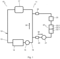
- FIG. 1 shows, in a highly schematic representation, a heating system 10 with an ion exchange cartridge 22 connected in a shunt.
- a heating water circuit 11 of the heating system 10 forms a flow 16 and a return 13.
- a fresh water connection 12 is provided on the heating water circuit 11 for filling the heating system 10 or for refilling heating water.
- a heat exchanger 14, a first pump 15, and a radiator 17 are integrated into the highly simplified heating water circuit 11.
- the heat exchanger 14 transfers thermal energy, which is provided, for example, by a gas or oil boiler, to the heating water.
- the heating water is pumped by the first pump 15 via the flow 16 to the radiator 17 in a flow direction 30 indicated by an arrow.
- the radiator 17 represents other radiators and is used to heat a building. From the radiator 17, the cooled heating water is led back to the heat exchanger 14 via the return line 13.
- the ion exchange cartridge 22 is designed as a multi-chamber cartridge, in this case as a two-chamber cartridge. It has a front chamber 22.1 and a downstream chamber 22.2. The front chamber 22.1 and the downstream chamber 22.2 are separated from each other by a filter disc 22.3.
- the ion exchange cartridge 22 is fluidly connected to the flow line 16 of the heating system 10 via a first shut-off valve 20 and a second pump 21.
- the second pump 21 causes heating water to be pumped from the flow line 16 of the heating system to the ion exchange cartridge 22 in the flow direction 30 indicated by an arrow.
- a mixed-bed cartridge 23 is arranged downstream of the ion exchange cartridge 22 in the flow direction.
- the mixed-bed cartridge 23 is connected to the flow line 16 of the heating system 10 via a second shut-off valve 24.
- the second pump 21 heating water is pumped from the flow 16 of the heating circuit 11 through the two chambers 22.1, 22.2 of the ion exchange cartridge 22, the filter disc 22.3 arranged therebetween and the subsequent mixed bed cartridge 23 and then fed back to the flow 16 of the heating circuit 11 via the second shut-off valve 24.
- the ion exchanger cartridge 22 is designed as a cation exchanger cartridge.
- a strongly acidic cation exchanger in sodium form is arranged in the front chamber 22.1.
- the cation exchanger in sodium form arranged in the front chamber 22.1 serves in a known manner to soften the heating water passing through.
- a cation exchanger loaded with a reducing agent is provided in the downstream chamber 22.2.
- the reducing agent is designed to remove oxygen from the heating water.
- the hydrogen ions of the strongly acidic cation exchanger were at least partially replaced by ions of the reducing agent, in this case by Fe 2+ ions.
- the heating water softened in the front chamber 22.1 is brought into contact with the reducing agent in the downstream chamber 22.2, the oxygen dissolved in the heating water is reduced by the reducing agent, and the reducing agent is correspondingly oxidized.
- the divalent iron ion Fe 2+ is oxidized to the trivalent iron ion Fe 3+ .
- the oxygen dissolved in the heating water is oxidized according to the reaction equation 4 Fe 2+ + O 2 + 2 H 2 O ⁇ 4 Fe 3+ + 4 OH - dismantled.
- the ion exchange cartridge 22 is designed as an anion exchange cartridge.
- a strongly basic anion exchanger loaded with a reducing agent is arranged in the front chamber 22.1 to remove oxygen from the heating water.
- the reducing agent is formed by sulfite ions SO 3 2- . These partially replace the OH groups. of the anion exchanger arranged in the front chamber 22.1.
- the following chamber 22.2 contains an anion exchanger in OH form.
- the heating water is alkalized by exchanging the anions present in the heating water for the hydroxide ions provided by the anion exchanger.
- the heating water can thus be both freed of oxygen and alkalized in accordance with the heating water guideline VDI 2035.
- the ion exchange cartridge 22 is advantageously arranged in the circulation of the heating water circuit 11.
- the heating water is thus passed proportionally through the ion exchange cartridge 22 in each circulation.
- the oxygen is completely or almost completely removed from the heating water, even at comparatively slow reaction rates between the oxygen and the reducing agent.
- the ion exchange cartridge 22 is connected to the flow line 16 of the heating system 10, the heating water passed through the ion exchange cartridge 22 has a comparatively high temperature.
- the high temperature advantageously noticeably increases the reaction rate between the oxygen and the reducing agent. This is particularly relevant for the reaction of oxygen with sulfite, since this reaction requires heat.
- oxygen-consuming chemicals are brought into contact with the heating water as reducing agents.
- the oxygen-consuming chemicals used When used with a strongly acidic cation exchanger, the oxygen-consuming chemicals used have an oxidation state that is below their maximum oxidation state.
- the oxygen dissolved in the heating water can thus absorb electrons from the oxygen-consuming chemical.
- the more highly charged ion after the oxidation reaction shows a higher affinity to the cation exchanger than the less charged ion, as can be seen from the selectivity series for ion exchange resins.
- the Fe 3+ ion formed has a higher affinity to the cation exchanger than the original Fe 2+ ion. This prevents Fe 3+ from entering the heating water in large quantities, for example in the form of iron(III) hydroxide, and causing sludge formation.
- the sulfate ions SO 4 2- formed by oxidation advantageously exhibit a higher affinity for the anion exchanger than the reduced form of the sulfite. This prevents the heating water from being overly contaminated with oxygen-depleting chemicals.
- An acidic, preferably strongly acidic, cation exchanger in its H form can be converted into the iron form using, for example, iron(II) sulfate.
- 2H + ions are replaced by the oxidation-sensitive or oxygen-consuming Fe2 + ion.
- the strongly acidic cation exchanger could already be in the sodium form before conversion to the iron form, so that in one embodiment, an ion exchange cartridge 22 could be produced which easily reduces the oxygen content of the heating water and simultaneously softens it.
- the ion exchange cartridge can then also be designed as a single-chamber cartridge.
- multivalent ions have a higher affinity for the exchange material.
- the cation exchanger can thus first be converted into its sodium form and then partially converted into the iron form by partial exchange of the monovalent Na + ions with divalent Fe 2+ ions.
- Such a cation exchanger is preferably present in the sodium form to a volume fraction of 10 to 50%.
- alkalization of the system water to be treated can also be achieved in accordance with the VDI 2035 Heating Water Guideline.
- the anion exchanger with the reducing agent is present in the OH form to a volume fraction of 5 to 10%, so that the capacity for oxygen removal and alkalization is exhausted with approximately the same amount of treated heating water.
- the ion exchanger cartridge 22 it is conceivable to design the ion exchanger cartridge 22 as a single-chamber cartridge.
- the cation exchange cartridges which are provided with a reducing agent for oxygen removal, and the anion exchange cartridges are preferably designed as single-bed cartridges.
- By-products formed during the oxygen removal process such as iron(III) hydroxide in the cation exchanger, which can lead to sludge formation, or sulfate in the anion exchanger, which has an adverse corrosion-chemical effect, can be Figure 1
- the inline process shown can be filtered out by the filter disc 22.3 or removed from the heating water by the downstream mixed-bed cartridge 23.
- a filter (not shown), in particular a depth filter, can be integrated into the heating water circuit 11.
- the filter can be integrated into the shunt of the heating water circuit, following the ion exchange cartridge.
- the filter can be used to remove the byproducts produced during the oxygen removal process.
- the mixed bed cartridge 23, which is connected downstream of the ion exchange cartridge 22 or is inserted at any point in the system water circuit, is advantageous because, depending on the composition of the system water, more or less iron ions can be removed from the ion exchange cartridge designed for oxygen reduction. 22 can be displaced. However, the oxygen-binding effect still unfolds within the heating water circuit.
- the ion exchange cartridge 22 preferably has a water inlet connection (not shown) and a water outlet connection (also not shown).
- the ion exchange cartridge 22 can thus be easily separated from the heating water circuit 11 for replacement, and a new ion exchange cartridge 22 can be connected to the heating water circuit 11.
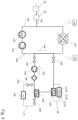
- FIG. 2 shows a further embodiment of a heating system according to the invention. 10
- This embodiment of a heating system 10 is based on the design variant according to Figure 1 or further develops them. Identical parts are numbered with the same reference numerals so that, to avoid repetition, reference can be made to the above explanations. Therefore, the following primarily focuses on the differences between the two design variants.
- the heating system 10 has an ion exchange cartridge 22 connected in shunt.
- a heating water circuit 11 of the heating system 10 forms a flow 16 and a return 13.
- a fresh water connection 12 is provided on the heating water circuit 11 for filling the heating system 10 or for refilling heating water.
- a further ion exchange cartridge 22 is arranged in the area of this fresh water connection 12. Additionally or alternatively, it may also be provided that a further mixed-bed cartridge 23 is integrated into the fresh water supply line.
- the additional mixed-bed cartridge 23 can be designed as already described above or as specified in the claims.
- the mixed-bed cartridge serves to at least partially demineralize the fresh water that is passed through the mixed-bed cartridge 23. To avoid repetition, reference is made to the above explanations.
- the further ion exchange cartridge 22 is integrated into the fresh water supply line together with a further mixed bed cartridge 23, wherein the further mixed bed cartridge 23 is preferably arranged downstream of the further ion exchange cartridge 22 in the flow direction.
- the heating water circuit 11, shown in a highly simplified manner, includes a heat exchanger 14, a first pump 15, and a radiator 17.
- the heat exchanger 14 transfers thermal energy, provided, for example, by a gas or oil boiler, to the heating water.
- the heating water is pumped by the first pump 15 via the flow line 16 to the radiator 17 in a flow direction 30 indicated by an arrow.
- the radiator 17 represents other radiators and serves to heat a building. From the radiator 17, the cooled heating water is directed back to the heat exchanger 14 via the return line 13.
- a shunt is derived from the heating water circuit 11.
- the shunt is branched off from the flow line 16 coming from the heat exchanger 14.
- the shunt can, as described above with regard to Figure 1
- the heating water circuit 11 can be blocked or released by means of two shut-off valves 20. In the released state, the heating water can be circulated in parallel through the flow and the shunt.
- a pump 21 is again provided.
- a depth filter 25 can optionally be used, which can be arranged upstream or downstream of the pump 21 in the flow direction.
- the depth filter 25 is arranged downstream of the pump 21.
- the depth filter 25 is arranged upstream of a mixed bed 23 or upstream of the ion exchange cartridge 22 in the flow direction.
- a first further shunt 27 is integrated into the shunt.
- a mixed bed cartridge 23 is inserted.
- This mixed bed cartridge 23 can be designed as already described above or as specified in the claims.
- the mixed bed cartridge serves to at least partially demineralize the heating water which is passed through the mixed bed cartridge 23.
- the first further shunt 27 has two shut-off valves 24. By means of these shut-off valves 24, the mixed bed cartridge 23 can be separated from the shunt. This makes it possible to replace the mixed bed cartridge 23, for example when it is exhausted.
- a control device can be provided, which in this case is designed in the form of a 3-way valve 26.
- the first additional shunt 27 can be coupled to the shunt in such a way that, depending on the position of the 3-way valve 26, the heating water flows via the first additional shunt 27 or bypasses this first additional shunt 27.
- the 3-way valve 26 may preferably be an electrically controlled 3-way valve 26.
- a measuring device can be provided that determines the conductivity of the heating water in the heating water circuit 11. If the measuring device signals an undesirably high conductivity of the heating water, the three-way valve 26 is controlled by a control device using a switching signal so that the heating water flows through the first additional shunt 27. The heating water then flows through the mixed-bed cartridge. 23. In the mixed-bed cartridge 23, the heating water is at least partially demineralized. This reduces the conductivity. The three-way valve 26 can be switched on until the conductivity returns to its desired value. Then the three-way valve 26 is switched over, and the heating water flows further in a bypass, for example, to an ion exchange cartridge 22.
- a second additional shunt 28 is also provided in the shunt.
- the second additional shunt 28 is connected to the shunt via a 3-way valve 26.
- the ion exchange cartridge 22 is integrated into the second additional shunt 28.
- the circulation of the heating water in the shunt can be controlled so that the heating water is either routed via the additional shunt 28 or that the heating water is routed in the shunt, bypassing the second additional shunt 28. This allows the ion exchange cartridge 22 to be switched on or off as needed.
- the heating water flows through the ion exchange cartridge 22 loaded with the reducing agent (and, if necessary, also through the upstream depth filter 25) over a predeterminable period of time, for example several hours per day.
- the heating water is not simultaneously passed through the mixed-bed cartridge 23 and the ion exchange cartridge 22. Then, depending on the desired operating mode, either the mixed-bed cartridge 23 or the ion exchange cartridge 22 can be decoupled from the shunt.
- both the mixed bed cartridge 23 and the ion exchange cartridge 22 are flowed through at the same time.
- fresh water is fed into the heating system 10 via the fresh water connection 12.
- the fresh water first flows through the additional ion exchange cartridge 22.
- oxygen is depleted, and the oxygen is removed from the supplied tap water. This significantly reduces the oxygen content.
- the supplied fresh water flows through the additional mixed-bed cartridge 23.
- the supplied fresh water is at least partially desalinated.
- the water thus treated, with a reduced oxygen content and in an at least partially desalinated state, is fed into the heating system. Accordingly, the water is already treated in an optimized manner with regard to corrosion protection.
- a heating system 10 is to be understood in which a further ion exchange cartridge 22 is integrated in the area of the fresh water connection 12 or in the area of the fresh water inlet, wherein optionally a mixed bed cartridge 23 is also integrated in the fresh water connection 12 or in the area of the fresh water inlet.
- a shunt as in the embodiments according to the Figures 1 and 2 shown, is omitted.
- the heating water is circulated in the heating water circuit 11. In doing so, the heating water also flows through the shunt. When flowing through the shunt, the heating water passed through the shunt at least partially permanently cleaned by the optional depth filter 25. Depending on the switching position of the 3-way valves 26, the heating water can be treated in the mixed-bed cartridge 23 and/or in the ion exchange cartridge 22.
- the shunt can be separated from the heating water circuit 11 by means of the two shut-off valves 20.
Landscapes
- Chemical & Material Sciences (AREA)
- Organic Chemistry (AREA)
- Chemical Kinetics & Catalysis (AREA)
- Life Sciences & Earth Sciences (AREA)
- Hydrology & Water Resources (AREA)
- Engineering & Computer Science (AREA)
- Environmental & Geological Engineering (AREA)
- Water Supply & Treatment (AREA)
- Treatment Of Water By Ion Exchange (AREA)
Applications Claiming Priority (2)
| Application Number | Priority Date | Filing Date | Title |
|---|---|---|---|
| DE102018129862.5A DE102018129862B4 (de) | 2018-11-27 | 2018-11-27 | Verfahren und Vorrichtung zur Reduzierung des Sauerstoffgehaltes von Heizungswasser |
| EP19211841.2A EP3659980B1 (fr) | 2018-11-27 | 2019-11-27 | Procédé et dispositif de réduction de la teneur en oxygène de l'eau de chauffage |
Related Parent Applications (1)
| Application Number | Title | Priority Date | Filing Date |
|---|---|---|---|
| EP19211841.2A Division EP3659980B1 (fr) | 2018-11-27 | 2019-11-27 | Procédé et dispositif de réduction de la teneur en oxygène de l'eau de chauffage |
Publications (2)
| Publication Number | Publication Date |
|---|---|
| EP4553047A2 true EP4553047A2 (fr) | 2025-05-14 |
| EP4553047A3 EP4553047A3 (fr) | 2025-05-21 |
Family
ID=68699355
Family Applications (2)
| Application Number | Title | Priority Date | Filing Date |
|---|---|---|---|
| EP25160930.1A Pending EP4553047A3 (fr) | 2018-11-27 | 2019-11-27 | Procédé et dispositif pour réduire la teneur en oxygène de l'eau de chauffage |
| EP19211841.2A Active EP3659980B1 (fr) | 2018-11-27 | 2019-11-27 | Procédé et dispositif de réduction de la teneur en oxygène de l'eau de chauffage |
Family Applications After (1)
| Application Number | Title | Priority Date | Filing Date |
|---|---|---|---|
| EP19211841.2A Active EP3659980B1 (fr) | 2018-11-27 | 2019-11-27 | Procédé et dispositif de réduction de la teneur en oxygène de l'eau de chauffage |
Country Status (2)
| Country | Link |
|---|---|
| EP (2) | EP4553047A3 (fr) |
| DE (1) | DE102018129862B4 (fr) |
Families Citing this family (2)
| Publication number | Priority date | Publication date | Assignee | Title |
|---|---|---|---|---|
| DE102021114126B4 (de) * | 2021-06-01 | 2023-12-21 | Perma-Trade Wassertechnik Gmbh | Vorrichtung und Verfahren zur Enthärtung und Reduzierung des Sauerstoffgehalts in Heizungsanlagen |
| DE102023136599A1 (de) * | 2023-12-22 | 2025-06-26 | Perma-Trade Wassertechnik Gmbh | Arbeitsmaschine mit einer Energieerzeugungs- oder Energieumwandlungsanlage, die eine mechanische, insbesondere elektromechanische Einheit, aufweist, insbesondere elektrischer Transformator |
Citations (5)
| Publication number | Priority date | Publication date | Assignee | Title |
|---|---|---|---|---|
| DE102005036356A1 (de) | 2005-07-29 | 2007-02-01 | Perma-Trade Wassertechnik Gmbh | Wasserbehandlungseinrichtung für eine Heizanlage |
| DE102008003327A1 (de) | 2008-01-07 | 2009-07-09 | Perma-Trade Wassertechnik Gmbh | Wasserbehandlungseinrichtung für eine Heizanlage |
| DE102009022437A1 (de) | 2009-05-23 | 2010-11-25 | Perma-Trade Wassertechnik Gmbh | Vorrichtung zur Behandlung von Wasser |
| DE102013102426A1 (de) | 2013-03-12 | 2014-10-02 | Perma-Trade Wassertechnik Gmbh | Verfahren und Vorrichtung zum Einstellen des pH-Wertes des Heizungswassers einer Heizungsanlage |
| DE102014103163A1 (de) | 2014-03-10 | 2015-09-10 | Perma-Trade Wassertechnik Gmbh | Steuerungseinrichtung und Verfahren zur Steuerung einer Entmineralisierungseinrichtung |
Family Cites Families (7)
| Publication number | Priority date | Publication date | Assignee | Title |
|---|---|---|---|---|
| CA622245A (en) * | 1961-06-20 | Nalco Chemical Company | Anion exchange contact process for removal of gases from fluids | |
| GB788112A (en) | 1955-03-24 | 1957-12-23 | Central Electricity Authority | Improvements in or relating to the removal of oxygen from water and solutions |
| BE587466A (fr) * | 1959-02-12 | 1900-01-01 | ||
| NL250278A (fr) * | 1959-04-09 | |||
| DD63334A1 (de) * | 1966-06-07 | 1968-08-05 | Walter Panovsky | Verfahren zur Entfernung von Oxydations- und Reduktionsmitteln, insbesondere Sauerstoff, aus wässrigen Lösungen |
| DE3120213A1 (de) * | 1981-05-21 | 1982-12-09 | Bayer Ag, 5090 Leverkusen | Verfahren zur durchfuehrung katalytischer reaktionen in waessrigen medien |
| DE102017105435A1 (de) * | 2017-03-14 | 2018-09-20 | Hans Sasserath Gmbh & Co Kg | Heizungsarmatur |
-
2018
- 2018-11-27 DE DE102018129862.5A patent/DE102018129862B4/de active Active
-
2019
- 2019-11-27 EP EP25160930.1A patent/EP4553047A3/fr active Pending
- 2019-11-27 EP EP19211841.2A patent/EP3659980B1/fr active Active
Patent Citations (5)
| Publication number | Priority date | Publication date | Assignee | Title |
|---|---|---|---|---|
| DE102005036356A1 (de) | 2005-07-29 | 2007-02-01 | Perma-Trade Wassertechnik Gmbh | Wasserbehandlungseinrichtung für eine Heizanlage |
| DE102008003327A1 (de) | 2008-01-07 | 2009-07-09 | Perma-Trade Wassertechnik Gmbh | Wasserbehandlungseinrichtung für eine Heizanlage |
| DE102009022437A1 (de) | 2009-05-23 | 2010-11-25 | Perma-Trade Wassertechnik Gmbh | Vorrichtung zur Behandlung von Wasser |
| DE102013102426A1 (de) | 2013-03-12 | 2014-10-02 | Perma-Trade Wassertechnik Gmbh | Verfahren und Vorrichtung zum Einstellen des pH-Wertes des Heizungswassers einer Heizungsanlage |
| DE102014103163A1 (de) | 2014-03-10 | 2015-09-10 | Perma-Trade Wassertechnik Gmbh | Steuerungseinrichtung und Verfahren zur Steuerung einer Entmineralisierungseinrichtung |
Also Published As
| Publication number | Publication date |
|---|---|
| DE102018129862A1 (de) | 2020-05-28 |
| EP4553047A3 (fr) | 2025-05-21 |
| EP3659980B1 (fr) | 2025-04-02 |
| EP3659980A1 (fr) | 2020-06-03 |
| DE102018129862B4 (de) | 2023-12-21 |
Similar Documents
| Publication | Publication Date | Title |
|---|---|---|
| EP0598249B1 (fr) | Procédé et appareil pour déminéraliser des solutions aqueuses à l'aide de masses échangeuses d'ions | |
| EP0113387B1 (fr) | Procédé et appareil pour traiter des liquides, en particulier pour déminéraliser des solutions aqueuses | |
| EP2094611B2 (fr) | Procédé et dispositif d'enrichissement d'eau en ions de magnésium | |
| DE102012003528B4 (de) | Wasserkonditionierungsvorrichtung zur Vermeidung oder Reduzierung von Mineralausfällungen | |
| EP3659980B1 (fr) | Procédé et dispositif de réduction de la teneur en oxygène de l'eau de chauffage | |
| DE2950875A1 (de) | Gegenstromverfahren zur behandlung von fluessigkeiten mit adsorptionsmitteln und vorrichtung zur durchfuehrung das verfahrens | |
| WO2016005174A1 (fr) | Ensemble pile à combustible comprenant un dispositif de désionisation interchangeable et véhicule comprenant un ensemble pile à combustible de ce type | |
| DE102005036356B4 (de) | Wasserbehandlungseinrichtung für eine Heizanlage | |
| DE60303393T2 (de) | Vorrichtung und verfahren zur regeneration eines bads zur stromlosen metallabscheidung | |
| AT514038B1 (de) | Verfahren und Vorrichtung zum Einstellen des pH-Wertes des Heizungswassers einer Heizungsanlage | |
| CH709327B1 (de) | Steuerungseinrichtung und Verfahren zur Steuerung einer Entmineralisierungseinrichtung. | |
| EP4098627A1 (fr) | Dispositif de réduction de la teneur en oxygène de l'eau de réalimentation pour installations de chauffage | |
| EP2836465B1 (fr) | Procédé permettant de faire fonctionner une installation de traitement de l'eau | |
| EP2390232A1 (fr) | Dispositif de traitement d'eau de processus | |
| EP4436926A1 (fr) | Système et procédé de traitement d'eau potable | |
| DE102006009522A1 (de) | Kombinationsverfahren zur Demineralisation von Wasser | |
| DE4031526C2 (de) | Verfahren zum Ionenaustausch an wässrigen Lösungen mittels Ionenaustauschharzen, sowie Anlage zur Durchführung des Verfahrens | |
| DE10153867B4 (de) | Umlaufheizanlage | |
| EP1558527A1 (fr) | Dispositif permettant d'empecher l'entartrage dans des systemes de circulation d'eau | |
| AT516911B1 (de) | Steuerungseinrichtung und Verfahren zur Steuerung einer Entmineralisierungseinrichtung | |
| AT528672A1 (de) | Verfahren und Vorrichtung zur gezielten Bildung von Calciumcarbonat-Ionenpaaren in kalkhaltigen Wässern | |
| DE3241681A1 (de) | Verfahren und vorrichtung zum behandeln von fluessigkeiten, insbesondere entsalzen waessriger loesungen | |
| DE8523228U1 (de) | Härtefühler | |
| DE2319559A1 (de) | Waermeaustauscher-einrichtung | |
| DE1261111B (de) | Ionenaustauscherharze als Filterhilfsmittel fuer Anschwemmfilter |
Legal Events
| Date | Code | Title | Description |
|---|---|---|---|
| PUAI | Public reference made under article 153(3) epc to a published international application that has entered the european phase |
Free format text: ORIGINAL CODE: 0009012 |
|
| STAA | Information on the status of an ep patent application or granted ep patent |
Free format text: STATUS: THE APPLICATION HAS BEEN PUBLISHED |
|
| REG | Reference to a national code |
Ref country code: DE Ref legal event code: R079 Free format text: PREVIOUS MAIN CLASS: C02F0001700000 Ipc: C02F0001420000 |
|
| PUAL | Search report despatched |
Free format text: ORIGINAL CODE: 0009013 |
|
| AC | Divisional application: reference to earlier application |
Ref document number: 3659980 Country of ref document: EP Kind code of ref document: P |
|
| AK | Designated contracting states |
Kind code of ref document: A2 Designated state(s): AL AT BE BG CH CY CZ DE DK EE ES FI FR GB GR HR HU IE IS IT LI LT LU LV MC MK MT NL NO PL PT RO RS SE SI SK SM TR |
|
| AK | Designated contracting states |
Kind code of ref document: A3 Designated state(s): AL AT BE BG CH CY CZ DE DK EE ES FI FR GB GR HR HU IE IS IT LI LT LU LV MC MK MT NL NO PL PT RO RS SE SI SK SM TR |
|
| RIC1 | Information provided on ipc code assigned before grant |
Ipc: C02F 103/02 20060101ALN20250414BHEP Ipc: C02F 1/70 20230101ALI20250414BHEP Ipc: B01J 47/016 20170101ALI20250414BHEP Ipc: B01J 41/07 20170101ALI20250414BHEP Ipc: B01J 41/05 20170101ALI20250414BHEP Ipc: B01J 39/17 20170101ALI20250414BHEP Ipc: B01J 39/07 20170101ALI20250414BHEP Ipc: B01J 39/05 20170101ALI20250414BHEP Ipc: C02F 1/42 20230101AFI20250414BHEP |
|
| STAA | Information on the status of an ep patent application or granted ep patent |
Free format text: STATUS: REQUEST FOR EXAMINATION WAS MADE |
|
| 17P | Request for examination filed |
Effective date: 20251121 |
|
| GRAP | Despatch of communication of intention to grant a patent |
Free format text: ORIGINAL CODE: EPIDOSNIGR1 |
|
| STAA | Information on the status of an ep patent application or granted ep patent |
Free format text: STATUS: GRANT OF PATENT IS INTENDED |
|
| RIC1 | Information provided on ipc code assigned before grant |
Ipc: C02F 1/42 20230101AFI20260225BHEP Ipc: B01J 39/05 20170101ALI20260225BHEP Ipc: B01J 39/07 20170101ALI20260225BHEP Ipc: B01J 39/17 20170101ALI20260225BHEP Ipc: B01J 41/05 20170101ALI20260225BHEP Ipc: B01J 41/07 20170101ALI20260225BHEP Ipc: B01J 47/016 20170101ALI20260225BHEP Ipc: C02F 1/70 20230101ALI20260225BHEP Ipc: C02F 103/02 20060101ALN20260225BHEP |
|
| INTG | Intention to grant announced |
Effective date: 20260324 |
|
| RAP3 | Party data changed (applicant data changed or rights of an application transferred) |
Owner name: PERMA-TRADE WASSERTECHNIK GMBH |
|
| RIC1 | Information provided on ipc code assigned before grant |
Ipc: C02F 1/42 20230101AFI20260313BHEP Ipc: B01J 39/05 20170101ALI20260313BHEP Ipc: B01J 39/07 20170101ALI20260313BHEP Ipc: B01J 39/17 20170101ALI20260313BHEP Ipc: B01J 41/05 20170101ALI20260313BHEP Ipc: B01J 41/07 20170101ALI20260313BHEP Ipc: B01J 47/016 20170101ALI20260313BHEP Ipc: C02F 1/70 20230101ALI20260313BHEP Ipc: C02F 103/02 20060101ALN20260313BHEP |