EP4553217A1 - Wäschetrockner - Google Patents
Wäschetrockner Download PDFInfo
- Publication number
- EP4553217A1 EP4553217A1 EP23208778.3A EP23208778A EP4553217A1 EP 4553217 A1 EP4553217 A1 EP 4553217A1 EP 23208778 A EP23208778 A EP 23208778A EP 4553217 A1 EP4553217 A1 EP 4553217A1
- Authority
- EP
- European Patent Office
- Prior art keywords
- flow
- condenser
- section
- fan
- air
- Prior art date
- Legal status (The legal status is an assumption and is not a legal conclusion. Google has not performed a legal analysis and makes no representation as to the accuracy of the status listed.)
- Pending
Links
Images



Classifications
-
- D—TEXTILES; PAPER
- D06—TREATMENT OF TEXTILES OR THE LIKE; LAUNDERING; FLEXIBLE MATERIALS NOT OTHERWISE PROVIDED FOR
- D06F—LAUNDERING, DRYING, IRONING, PRESSING OR FOLDING TEXTILE ARTICLES
- D06F58/00—Domestic laundry dryers
- D06F58/02—Domestic laundry dryers having dryer drums rotating about a horizontal axis
-
- D—TEXTILES; PAPER
- D06—TREATMENT OF TEXTILES OR THE LIKE; LAUNDERING; FLEXIBLE MATERIALS NOT OTHERWISE PROVIDED FOR
- D06F—LAUNDERING, DRYING, IRONING, PRESSING OR FOLDING TEXTILE ARTICLES
- D06F58/00—Domestic laundry dryers
- D06F58/20—General details of domestic laundry dryers
- D06F58/206—Heat pump arrangements
-
- D—TEXTILES; PAPER
- D06—TREATMENT OF TEXTILES OR THE LIKE; LAUNDERING; FLEXIBLE MATERIALS NOT OTHERWISE PROVIDED FOR
- D06F—LAUNDERING, DRYING, IRONING, PRESSING OR FOLDING TEXTILE ARTICLES
- D06F58/00—Domestic laundry dryers
- D06F58/20—General details of domestic laundry dryers
-
- D—TEXTILES; PAPER
- D06—TREATMENT OF TEXTILES OR THE LIKE; LAUNDERING; FLEXIBLE MATERIALS NOT OTHERWISE PROVIDED FOR
- D06F—LAUNDERING, DRYING, IRONING, PRESSING OR FOLDING TEXTILE ARTICLES
- D06F58/00—Domestic laundry dryers
- D06F58/20—General details of domestic laundry dryers
- D06F58/24—Condensing arrangements
-
- F—MECHANICAL ENGINEERING; LIGHTING; HEATING; WEAPONS; BLASTING
- F25—REFRIGERATION OR COOLING; COMBINED HEATING AND REFRIGERATION SYSTEMS; HEAT PUMP SYSTEMS; MANUFACTURE OR STORAGE OF ICE; LIQUEFACTION SOLIDIFICATION OF GASES
- F25B—REFRIGERATION MACHINES, PLANTS OR SYSTEMS; COMBINED HEATING AND REFRIGERATION SYSTEMS; HEAT PUMP SYSTEMS
- F25B30/00—Heat pumps
-
- F—MECHANICAL ENGINEERING; LIGHTING; HEATING; WEAPONS; BLASTING
- F25—REFRIGERATION OR COOLING; COMBINED HEATING AND REFRIGERATION SYSTEMS; HEAT PUMP SYSTEMS; MANUFACTURE OR STORAGE OF ICE; LIQUEFACTION SOLIDIFICATION OF GASES
- F25B—REFRIGERATION MACHINES, PLANTS OR SYSTEMS; COMBINED HEATING AND REFRIGERATION SYSTEMS; HEAT PUMP SYSTEMS
- F25B39/00—Evaporators; Condensers
- F25B39/04—Condensers
Definitions
- the present invention relates to the technical field of tumble dryers, and in particular to a condenser for a heat pump tumble dryer.
- Tumble dryers are an important keystone within the laundry industry, both in professional environments such as hotels, hospitals or laundromats, as well as in private environments such as people's homes.
- the first one uses a passive heat exchanger to cool the process air, i.e. the air circulating into and out from the drying drum to dry the wet laundry, and condense the water vapor into a drain pipe or collection tank, often using ambient air as the coolant.
- the latter, the heat pump dryer utilizes a heat pump in a closed loop system to dehumidify the process air.
- the heat pump typically includes, amongst others, a condenser and an evaporator, where the evaporator of the heat pump condenses the water vapor, and the condenser reheats the air for re-use into the drying drum, i.e. the process air flows in a closed loop.
- a condenser and an evaporator where the evaporator of the heat pump condenses the water vapor, and the condenser reheats the air for re-use into the drying drum, i.e. the process air flows in a closed loop.
- a tumble dryer comprising a rotatable drum arranged in a housing, a first fan arranged to generate a flow of process air passing through the drum, and a second fan arranged to generate a flow of ambient air passing from an air inlet towards an air outlet of the housing.
- the tumble dryer further comprises a heat pump for drying the process air before entering the drum, the heat pump comprising a condenser divided into a first and a second section.
- the first section is configured to condense the process air flow being led through the first section by the first fan
- the second section is configured to condense the ambient air flow being led through the second section by the second fan.
- the process air flow is independent from the external air flow.
- the tumble dryer comprises a heat pump for drying the process air before it enters the drum.
- the heat pump further comprises a compressor, an evaporator, and at least one expansion device.
- the process air flowing through the heat pump may be heated by the first section of the condenser such that dried, heated process air may enter the drum and dry the laundry placed therein.
- the process air may then leave the drum as hot, humid air, and flow back to the heat pump where it is cooled and dehumidified by the evaporator.
- the cold and dry process air may then flow pass the compressor where it is preheated, before passing through the first section of the condenser again where it is heated and dried, and then flow back into the drum again.
- the expansion device may be positioned between the condenser and the evaporator in order to control the flow of refrigerant in the system.
- the process air flow may therefore be a closed loop air flow.
- the process air flow is circulated in the loop by the first fan.
- the first fan may be an electrical fan or a mechanical fan, for example. Further, the first fan may be an axial fan, a propeller fan, or a radial fan. It will be appreciated that other types of fans are also possible.
- the first fan may be placed in the process air flow, for example after the drum and before the heat pump in the flow direction.
- the first section of the condenser together with the further components of the heat pump and the drum may operate as a conventional heat pump tumble dryer.
- the first and second sections of the condenser together form one and the same unit.
- the condenser may be formed as one piece component, which is advantageous since it facilitates manufacturing. For example, standard manufacturing processes for condensers may be maintained.
- the second section of the condenser may be controlled by controlling the second fan.
- the condenser may be controlled by controlling the speed of the second fan.
- the second fan may for example be driven by a motor, in order to adjust a speed thereof.
- the motor may be a step motor, a gear motor, or any other means suitable for adjusting the speed of a fan.
- the second fan may thus be an electrical fan.
- the second fan may be an axial fan, a propeller fan, or a radial fan, for example. It will be appreciated that other types of fans are also possible.
- the second fan is placed in the ambient air flow, which may draw in an air flow from the environment surrounding the tumble dryer, and flow through a duct in the tumble dryer, whereafter it is released to the surrounding environment again.
- the duct leading the ambient air flow may be separated from the closed loop where the process air flow is led.
- the ambient air flow and the process air flow are independent from each other.
- the ambient air flow may be an open loop air flow with a separated air inlet and air outlet.
- the duct may have an air inlet at one end thereof, and an air outlet at the other end. Ambient air may then be continuously drawn into the duct through the air inlet, flow through the duct, and be released at the air outlet.
- the second fan and the second section of the condenser may be arranged in the duct, between the air inlet and the air outlet.
- the cooling effect of the fan may be controlled, where a higher speed means a greater cooling effect, since a greater volume of air may be moved per time unit compared to a fan running on a lower speed, resulting in a lower cooling effect.
- the second fan may create the ambient air flow by drawing in air through the air inlet, and transferring the air through the duct towards the air outlet. Thereby the second fan may lead the ambient air flow through the second section of the condenser, which condenses the ambient air flow.
- an energy exchange takes place between the ambient air flow and the second section of the condenser, where the second section of the condenser is cooled by the ambient air flow, which takes up some of the heating energy of the condenser, thereby cooling it.
- the ambient air has an increased temperature when leaving the second section of the condenser.
- the capacity of the condenser may be advantageously controlled, leading to a balanced capacity between the condenser and evaporator. Further, controlling the capacity of the condenser by having the two sections enables for separately managing the heat transfer regions in the first section of the condenser, namely the gas desuperheating region and the gas condensation process. By controlling the capacity of the condenser by controlling the second section of the condenser, it is possible to make use of the higher temperatures in the gas desuperheating region in the condenser, to increase the capability of the air to absorb an increased amount of moisture from the textiles in a more flexible and efficient way. Thereby the drying performance of the tumble dryer can be improved.
- the first section of the condenser is configured to receive a flow of refrigerant
- the second section is configured to receive the flow of refrigerant from the first section of the condenser.
- the flow of refrigerant may be provided by controlling the expansion device, which may be connected to the first section of the condenser.
- the first section of the condenser may thus receive the flow of refrigerant, which then flows through the first section of the condenser, and thereafter flows into the second section of the condenser.
- the heating capacity of the condenser may be controlled by controlling the speed of the second fan, as mentioned above. This configuration may be beneficial in dynamic processes, i.e. when the thermal loads vary with time, since the speed of the fan may be controlled throughout the drying process, to either speed up or slow down.
- the first section of the condenser is configured to receive a first flow of refrigerant
- the second section is configured to receive a second flow of refrigerant, wherein the first flow and the second flow are different from each other.
- the first flow of refrigerant may be provided to the first section of the condenser by controlling the first expansion device which may be connected to the first section of the condenser
- the second flow of refrigerant may be provided to the second section of the condenser by controlling the second expansion device which may be connected to the second section of the condenser.
- the first section of the condenser may receive a smaller flow of refrigerant compared to the flow of refrigerant received by the second section of the condenser, which may then have a larger flow.
- the second fan may in this example have a constant speed throughout the process.
- the tumble dryer further comprises a control unit.
- the control unit may be connected to the first fan and the second fan.
- the control unit is configured to control a speed of the second fan.
- the control unit may further include sensing devices, to be able to read and detect various information from the system. For example, there may be a temperature sensor detecting the temperature in the drum, sending the same information to the control unit.
- the control unit may be connected to the expansion device or expansion devices, receiving information about a flow of refrigerant. The control unit may automatically control the different parameters of the system, e.g. the speed of the second fan, depending on the information it receives.
- the control unit is configured to control a speed of the compressor.
- the compressor controls the pressure and temperature of the refrigerant.
- the pressure and temperature of the refrigerant may be varied. Comparing with a compressor running on constant speed, where the temperature and pressure of the refrigerant remains constant, the output of the compressor with variable speed may be advantageously controlled. In a tumble dryer with a compressor running on constant speed, the output from the compressor will be the same regardless of the values of other parameters in the tumble dryer, such as laundry load, ambient temperature, air pressure, etc.
- the control unit may thus be configured to, based on the other parameters in the tumble dryer, for example laundry load, adapt the speed of the compressor to match the desired output.
- This is further advantageous since it allows for the process to be controlled in a way enabling the drying process to be optimized at different parameters. For example, by controlling the speed of the compressor, the efficiency of the compressor and the heat pump as a whole may be improved, and power costs may be reduced.
- the capacity of the compressor may be aligned with the capacity of the remainder of the system, for example the condenser, to reach a capacity balance between the different components in the system.
- the second fan is arranged between the air inlet and the second section of the condenser in the ambient air flow.
- the air inlet may for example be arranged on a lower side of the tumble dryer.
- the air outlet may in this example be arranged on an upper side of the tumble dryer.
- the ambient air may therefore flow from a lower side up and towards the upper side of the tumble dryer.
- the second fan is placed between the air inlet and the second section of the condenser, i.e. before the condenser in the ambient air flow direction.
- the second section of the condenser may be placed close to the air outlet of the second fan, meaning that the flow of air coming from the second fan may maintain the speed it had when leaving the fan when entering the condenser.
- This is beneficial since it facilitates the control of the second section of the condenser, since no consideration needs to be taken to speed loss, in comparison to if the air from the fan had to travel a longer distance before entering the condenser.
- the second fan is arranged between the second section of the condenser and the air outlet in the ambient air flow.
- the second fan may then be placed after the second section of the condenser in the ambient air flow direction.
- the second fan be directed to blow air in the direction towards the air outlet of the ambient air flow in the tumble dryer.
- the air exiting the condenser may be drawn out by the second fan, by a suction force thereof.
- the speed of the second fan may control the speed at which air is drawn out from the second section of the condenser.
- This is advantageous since it is possible to place the second fan in different positions, increasing the flexibility of the tumble dryer. For example, if space is an issue, the fan may be moved to a different position to save space, while maintaining the performance of the tumble dryer.
- the tumble dryer further comprises an air damper in the ambient air flow.
- the air damper may be used to further control the flow of ambient air through the tumble dryer assembly.
- the air damper may for example be a flap, a set of blades, or similar, installed in the ambient air flow duct.
- the air damper prevents a possible undesired heat transfer via natural convection when more energy is needed in the first section of the condenser. This is advantageous since it adds a further possibility to control the ambient air flow through the condenser, which enables a further control of the second section of the condenser, leading to an improved performance of the tumble dryer.
- the air damper is arranged between the second section of the condenser and the air outlet in the ambient air flow.
- the air damper may be placed upstream the second section of the condenser in the ambient air flow direction.
- the air damper may thus be closed to cut off the air flow towards the air outlet of the ambient air flow, and thereby control the ambient air flow, preventing heat exchange by natural convection with the surrounding air outside of the tumble dryer.
- the condenser is a microchannel condenser or a fin-and-tube condenser.
- the evaporator is a microchannel evaporator or a fin-and-tube evaporator.
- Microchannel condensers allow for the weight of the condenser to be advantageously decreased without decreasing the performance of the condenser. Further, a smaller amount of refrigerant is needed to achieve the same heating capacity.
- Microchannel evaporators allow for the weight of the evaporator to be advantageously decreased without decreasing the performance of the evaporator. Further, a smaller amount of refrigerant is needed to achieve the same cooling capacity.
- Fin and tube condensers are advantageous in applications where air is the preferred medium for heating. Further, fin and tube condensers may be manufactured in a range of designs and in different materials, which make them versatile. Fin and tube evaporators are advantageous in applications where air is the preferred medium for cooling. Further, fin and tube evaporators may be manufactured in a range of designs and in different materials, which make them versatile. It will be appreciated that other types of condensers and/or evaporators are possible.
- the evaporator is arranged with an angle to a direction of the flow of process air, the angle being in a range between 0 and 180 degrees. In a preferred embodiment, the angle is larger than 0 degrees but smaller than 90 degrees. In another preferred embodiment, the angle is larger than 90 degrees but smaller than 180 degrees.
- the direction of the flow of process air may be a direction in which the fan arrangement directs the flow of process air coming from the drum.
- the direction of the flow of process air may be substantially horizontal, and the evaporator may then for example have a 135 degree angle relative to the direction of the flow of process air after the fan arrangement.
- the angle of the evaporator may be less than 135 degrees, more specifically 95 to 130 degrees.
- the evaporator may have a substantially rectangular shape, with a height and a width and a thickness.
- the size of the surface area of the evaporator may thus be defined by the dimensions of the height and the width.
- Arranging the evaporator with an angle means that for example the height of the evaporator may be increased without the need to increase the size of the housing of the tumble dryer. This is advantageous in that a size of the surface of the evaporator may be increased, meaning that an increased amount of air may be cooled at the same time, ultimately increasing the cooling capacity of the evaporator.
- the angled placement of the evaporator further enables condensed water on the surface of the evaporator, to be efficiently drained.
- the condensed water may fall down from the surface by force of gravity, and be drained in the bottom of the housing.
- the angular arrangement of the evaporator is beneficial since it decreases the risk of recirculating humid air into the heat pump.
- the tumble dryer 100 has a housing 120 with a front side 101 which is provided with a door 102 or hatch, attached to the front side 101 with hinges 103.
- the door 102 in the housing 120 provides access to a rotatable drum 110 behind the door 102 where wet laundry may be loaded.
- FIG. 2 illustrates a cross-section of the tumble dryer 100.
- the tumble dryer 100 comprises a rotatable drum 110 in which wet laundry is placed.
- the tumble dryer 100 further comprises an air inlet 150 and an air outlet 160 arranged in the housing 120, in the rear part of the tumble dryer 100.
- the air inlet 150 and the air outlet 160 allows a flow of ambient air 145 to enter and exit the housing 120.
- a flow of process air 135 is fed therethrough.
- the flow of process air 135 is provided by a first fan 130 or blower, which in the illustrated embodiment is located in a space beneath the drum 110.
- the tumble dryer 100 further comprises a heat pump 200 with a condenser 210, a compressor 220, an evaporator 230, and at least one expansion device 240 (cf. figure 5 ).
- a refrigerant is forced through the heat pump 200 by the compressor 220, and gathers energy in the evaporator 230 which is released in the condenser 210.
- the flow of process air 135 is achieved where hot, humid air is extracted from the rotatable drum 110 by means of the first fan 130.
- the flow of process air may pass a filter 137 before reaching the first fan 130 and arrives at the evaporator 230, which cools the flow of process air 135 such that moisture therein condenses into liquid water.
- This water may be collected in the bottom section of the tumble dryer and may therefrom be drained through a tube (not shown).
- the flow of process air 135, which is now cooler and contains less water, is passed to the condenser 210, which heats the air again. Then the heated, dry air is reintroduced into the drum 110 where it is again capable of absorbing water from the laundry therein.
- a heat pump assembly comprising the heat pump 200 according to an exemplifying embodiment of the present disclosure is shown.
- the heat pump 200 may be partially enclosed by a shell 201, for protecting the components of the heat pump 200.
- the shell 201 may package the heat pump 200, such that the heat pump 200 may be lifted out from the tumble dryer 100 as one unit. This is beneficial if, for example, a component in the heat pump 200 needs to be replaced, or if the entire heat pump 200 needs to be replaced. In this way, the tumble dryer 100 may be repaired in an efficient way, increasing its life span.
- the heat pump assembly comprises a heat pump outlet 202 for allowing the flow of process air 135 from the heat pump 200 into the drum 110.
- the heat pump assembly further comprises a heat pump inlet 203 for receiving the flow of process air 135 from the drum 110 to the heat pump 200, via the first fan 130.
- the heat pump outlet 202 may be placed, as depicted in the present figure, in a top side of the heat pump assembly, above the internal components of the heat pump 200, such as the compressor 220, the evaporator 230, the expansion device 240 and the condenser 210 (located behind the shell 201 and thus not shown in figure 3 ). Further, the heat pump inlet 203 may be placed on a bottom side of the heat pump assembly, below the condenser 210. The heat pump inlet 203 may be partially covered by the evaporator 230.
- the evaporator 230 is shown arranged in an angle relative the direction of the flow of process air F.
- the heat pump inlet 203 in which the evaporator 230 is arranged is a rectangular opening through which the flow of process air may enter in a direction F, seen from a front of the heat pump inlet 203 in the present figure.
- the direction F of the flow of process air 135 may be horizontal.
- the evaporator 230 may have a rectangular shape corresponding to the shape of the heat pump inlet 203.
- a height of the heat pump inlet 203 may thus limit a height of the evaporator 230 if the evaporator is intended to be arranged in the same plane as the heat pump inlet 203, for example a vertical plane, shown in figure 3 .
- a height of the evaporator may thus be increased when the evaporator 230 is arranged with an angle, not limited by the height of the heat pump inlet 203.
- an increased amount of air coming from the drum may be cooled and dehumidified, increasing the cooling capacity of the evaporator.
- the angled arrangement of the evaporator 230 further enables condensed water (not shown) on the surface of the evaporator, to be efficiently drained. The condensed water may fall down from the surface by force of gravity, and be drained in the bottom of the housing 120.
- the angular arrangement of the evaporator 230 is beneficial since it decreases the risk of recirculating humidified air into the heat pump 200.
- the shell 201 may provide a duct for the flow of process air 135, since it partially encloses the heat pump 200.
- the flow of process air 135 procduced by the first fan 130 may be lead by the shell 201, through the condenser 210 and towards the heat pump outlet 202.
- Figure 3 further shows the air inlet 150, allowing an ambient air flow 145 to flow into the heat pump assembly.
- the air outlet 160 is arranged on a rear side of the heat pump assembly as depicted in the figure.
- the air outlet 160 may thus be on an opposite side of the heat pump assembly as the heat pump outlet 202.
- the air outlet 160 allows an ambient air flow 145 to exit the heat pump assembly and the tumble dryer 100 and flow out to the surrounding environment.
- the surrounding environment may be the room, or premises where the tumble dryer 100 has been installed.
- the tumble dryer 100 may further comprise a control unit 300 arranged in the heat pump assembly shown in figure 3 .
- the control unit 300 may be configured to control the first 130 and second 140 fans, by controlling a speed of the first 130 and/or second fan 140.
- the control unit 300 may further control the compressor 220.
- the compressor 220 may be controlled so as to adapt a speed of a motor in the compressor 220.
- the compressor 220 controls the pressure and temperature of the refrigerant. By controlling a speed of the compressor 220, the pressure and temperature of the refrigerant may be varied.
- the control unit 300 may thus control several parameters of the drying process, to deliver satisfying drying results for different laundry loads, ambient temperatures, etc. This is advantageous since the previously mentioned parameters may not always be possible to control, such as the ambient air temperature, for example.
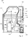
- the heat pump assembly comprising the heat pump 200 according to an exemplifying embodiment of the present disclosure is shown, in a cross-sectional view.
- the evaporator 230 is not shown in this figure.
- the heat pump 200 comprises a compressor 220, an expansion device 240, an evaporator 230 and a condensor 210.
- the second fan 140 is arranged in the ambient air flow 145.
- the first fan (not shown in present figure) is arranged below the rotatable drum (not shown in present figure) and produces the flow of process air 135.
- the condenser 210 comprises a first section 211, and a second section 212.
- the first 211 and second 212 sections are arranged in the flow of process air 135 and the ambient air flow 145, respectively.
- the heat pump 200 is divided into two sections by a dividing wall 204.
- the dividing wall 204 is arranged between the first 211 and second 212 section of the condenser 210. As seen in the figure, the dividing wall 204 further divides the ambient air flow 145 from the flow of process air 135.
- the second fan 140, the second section of the condenser 212, the air inlet 150 and the air outlet 160 are arranged on one side of the dividing wall 204.
- the first section of the condenser 211, the first fan 130, the evaporator 230, the compressor 220 and the expansion device 240 are arranged on the other side of the dividing wall 204.
- the flow of process air 135 and the ambient air flow 145 are independent from each other, in the sense that they are physically separated from each other, and in another sense that they are produced by two independent fans, the first fan 130 and the second fan 140.
- the flow of process air 135 passes through the first section 211 of the condenser 210, where it is heated by the refrigerant that has been pressurized by the compressor 220 before entering the first section 211 of the condenser 210.
- the refrigerant releases its heat and its temperature decreases.
- the refrigerant is then fed through the expansion device 240 where the pressure is decreased along with the temperature.
- the refrigerant is thereafter returned to the evaporator 230 with a lower temperature, where it is used to cool and dehumidify the warm, humid flow of process air 135 exiting the rotatable drum 110.
- the heating capacity of the first section 211 of the condenser 210 exceeds the cooling capacity of the evaporator 230. Therefore, heat has to be rejected outside of the closed-loop system produced by the heat pump 200, the first fan 130 and the rotatable drum 110 in order to achieve balance.
- the amount of heat needing to be rejected to achieve balance varies depending on parameters such as layndry load, ambient air temperature, air pressure, etc.
- the second section 212 of the condenser 210 bridges this difference in capacity by being arranged in a separate, ambient air flow 145.
- the ambient air flow 145 is produced by the second fan 140 which draws ambient air into the heat pump assembly.
- the second fan 140 is placed below, and thus upstream, the second section 212 of the condenser 210 in the direction of the ambient air flow 145.
- the ambient air has a lower temperature than the temperature of the flow of process air 135.
- the second section 212 of the condenser 210 may remove a significant amount of energy from the condenser, by decreasing the temperature of the refrigerant and increasing the cooling capacity of the evaporator, since the ambient air flow 145 does not return back to the evaporator 230, but is instead released to the surrounding environment. Therefore, the difference in capacity may be balanced through the second section 212 of the condenser 210. Further, since the speed of the second fan 140 is controlled by the control unit 300, the amount of heat that should be rejected outside of the system may be advantageously controlled. The speed of the second fan 140 may be increased if the heat rejection should increase, and decreased if the heat rejection should be decreased. There are two possible working modes of the condenser 210, 'series configuration' and 'parallel configuration', which will now be explained in more detail.
- the flow of refrigerant flowing to the condenser 210 from the compressor 220 is delivered to the first section 211, from where it flows into the second section 212 and then back to the evaporator 230, via the expansion device 240.
- the same flow of refrigerant is delivered to the first section 211 and the second section 212.
- the parameter controlling the amount of rejected heat is thus the speed of the second fan 140.
- the flow of refrigerant flowing to the condenser 210 from the compressor 220 is divided into two flows, one flow entering the first section 211, and one flow entering the second section 212, respectively.
- the flow of refrigerant may be divided by splitting the pipe delivering the refrigerant from the compressor 220 into two pipes, one connected to the first section 211, and the other one connected to the second section 212.
- the configuration further comprises two expansion devices, one expansion device 240 connected to the pipe leading from the first section 211 to the evaporator 230, and a second expansion device (not shown) leading from the second section 212 to the evaporator 230. In this way, the flow of refrigerant delivered to the first 211 and second 212 section may be different.
- the control unit 300 may control the two expansion devices to control the flow of refrigerant through the first 211 and second 212 sections.
- the expansion devices may be mechanical or fixed pressure drop devices, which may be self-regulated without the need of a control unit.
- the size of the heat rejection from the condenser 210 may be further controlled by splitting the control of the heating capacity between the first 211 and second 212 section.
- An increased flow of refrigerant means an increased heating capacity, because of the higher flow rate.
- a decreased flow of refrigerant means a decreased heating capacity, since the flow rate is lower.
- the flow rate may therefore be increased in the second section 212 if an increased heat rejection is desired, and vice versa.
- the second fan 140 and the flow of refrigerant may advantageously be controlled in order to balance the capacities between the evaporator 230 and the condenser 210.
- the heat pump assembly further comprises an air damper 147 arranged in the ambient air flow 145.
- the air damper 147 is a plate arranged above, and thus downstream the second fan 140 and the second section 212 of the condenser 210 in the direction of the ambient air flow 145.
- the plate 147 may be rotatably arranged in the duct delimited by the dividing wall 204 and the enclosing shell 201 of the heat pump assembly.
- the condenser 210 may for example be a finned multi-row condenser 210 or a microchannel condenser 210, with multiple parallel rows.
- the first section 211 comprises two separate rows 211a, 211b and one shared row 210a
- the second section 212 comprises one separate row 212a and one shared row 210a.
- the shared row 210a is thus common for the first 211 and second 212 section of the condenser 210.
- the refrigerant flows through the rows 210a, 211a, 211b, 212a in the condenser 210 as the flow of process air 135 and ambient air flow 145 flows through cavities between the micro channels or finned tubes, and thereby takes up heat from the refrigerant.
- the condenser 210 further comprises a divider 215, dividing the first 211 and second 212 sections.
- the divider 215 comprises two plates, one arranged in one end of the rows 211a, 211b between the first section 211 and the second section 212. The other plate is arranged between the first 211 and the second 212 section in one end of the row 210a.
- a condenser 210 according to an exemplifying embodiment of the present disclosure is shown.
- the condenser 210 depicted in the figure is adapted to the 'series configuration'.
- the condenser 210 is shown from a side view.
- the first section 211 of the condenser 210 is connected to a pipe 211f.
- the pipe 211f delivers refrigerant to the first section 211 of the condenser 210.
- the refrigerant then flows from the top row 211a, down to and through the second row 211b, down to and through the shared row 210a, down to and then through the row 211a, from where it then leaves the second section of the condenser 212 through the pipe 212f which leads to the expansion device 240 and further into the evaporator 230.
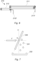
- an evaporator 230 arranged at an angle ⁇ relative the direction F of the flow of process air 135 is shown.
- the evaporator 230 is shown from a side view, and a flow of process air 135 with the direction F is entering the evaporator 230 in a front of the evaporator 230.
- a vertical plane V is shown to illustrate the angular placement of the evaporator relative the direction F of the flow of process air, and to the vertical plane V.
- angle ⁇ is shown, being the angle between the direction F of the flow of process air 135, and the evaporator 230.
- the angle ⁇ may range from 0 degrees to 180 degrees.
- the evaporator 230 when ⁇ equals 0 degrees, the evaporator 230 is parallel with the direction F of the flow of process air 135. When the angle ⁇ equals 180 degrees, the evaporator 230 is also parallel with the direction F of the flow of process air 135. Thus, when the angle ⁇ equals 90 degrees, the evaporator 230 is perpendicular to the direction F of the flow of process air 135. In figure 7 , the direction F is shown as a horizontal direction. Thus, if the evaporator 230 is arranged with a 90 degree angle relative the direction F in this example, the evaporator 230 would be parallel with the vertical plane V.
- the vertical plane V may correspond to the plane formed by the heat pump inlet 203 (not shown in the present figure). As seen in figure 7 , condensed water 231 from the evaporator 231 drops down by the force of gravity, and may be collected by a drainage collector 232 located in the bottom of the housing 120.
- the condensed water 231 cannot drop down from the evaporator 230, but rather has to run down the surface of the evaporator 230 while new humidified air is passing therethrough.
Landscapes
- Engineering & Computer Science (AREA)
- Textile Engineering (AREA)
- Drying Of Solid Materials (AREA)
Priority Applications (1)
| Application Number | Priority Date | Filing Date | Title |
|---|---|---|---|
| EP23208778.3A EP4553217A1 (de) | 2023-11-09 | 2023-11-09 | Wäschetrockner |
Applications Claiming Priority (1)
| Application Number | Priority Date | Filing Date | Title |
|---|---|---|---|
| EP23208778.3A EP4553217A1 (de) | 2023-11-09 | 2023-11-09 | Wäschetrockner |
Publications (1)
| Publication Number | Publication Date |
|---|---|
| EP4553217A1 true EP4553217A1 (de) | 2025-05-14 |
Family
ID=88792695
Family Applications (1)
| Application Number | Title | Priority Date | Filing Date |
|---|---|---|---|
| EP23208778.3A Pending EP4553217A1 (de) | 2023-11-09 | 2023-11-09 | Wäschetrockner |
Country Status (1)
| Country | Link |
|---|---|
| EP (1) | EP4553217A1 (de) |
Citations (3)
| Publication number | Priority date | Publication date | Assignee | Title |
|---|---|---|---|---|
| EP2468948A2 (de) * | 2010-12-21 | 2012-06-27 | Panasonic Corporation | Vorrichtung zur Entfeuchtung und Erwärmung sowie Wäschetrockner damit |
| US20170314181A1 (en) * | 2014-11-19 | 2017-11-02 | Samsung Electronics Co., Ltd. | Dryer |
| US20180066893A1 (en) * | 2015-02-04 | 2018-03-08 | Qingdao Haier Washing Machine Co., Ltd. | Air condenser and clothes dryer |
-
2023
- 2023-11-09 EP EP23208778.3A patent/EP4553217A1/de active Pending
Patent Citations (3)
| Publication number | Priority date | Publication date | Assignee | Title |
|---|---|---|---|---|
| EP2468948A2 (de) * | 2010-12-21 | 2012-06-27 | Panasonic Corporation | Vorrichtung zur Entfeuchtung und Erwärmung sowie Wäschetrockner damit |
| US20170314181A1 (en) * | 2014-11-19 | 2017-11-02 | Samsung Electronics Co., Ltd. | Dryer |
| US20180066893A1 (en) * | 2015-02-04 | 2018-03-08 | Qingdao Haier Washing Machine Co., Ltd. | Air condenser and clothes dryer |
Similar Documents
| Publication | Publication Date | Title |
|---|---|---|
| US10793995B2 (en) | Condensing type clothes dryer having a heat pump cycle and a method for controlling a condensing type clothes dryer having a heat pump cycle | |
| US9803313B2 (en) | Clothes treating apparatus | |
| CN106855353B (zh) | 具有除湿型与排湿型切换功能的热泵干燥设备及干燥方法 | |
| KR101224157B1 (ko) | 히트 펌프형 건조기 | |
| US6321460B1 (en) | Drying apparatus | |
| US20130008049A1 (en) | Device and method for heat pump based clothes dryer | |
| CN105324529B (zh) | 热泵式衣物干燥机 | |
| CN105316920B (zh) | 干衣机和干衣机热泵系统及其控制方法 | |
| CN110799695A (zh) | 闭式热泵干衣机系统 | |
| KR20120096916A (ko) | 히트 펌프형 건조 시스템 | |
| CN107255411A (zh) | 一种多功能热泵烘干装置 | |
| CN115323735B (zh) | 一种基于微通道脉动热管的热泵干衣机及控制方法 | |
| KR100737006B1 (ko) | 의류 건조 장치 | |
| CN220552252U (zh) | 一种热泵烘干机新风除湿干燥系统 | |
| CN217465307U (zh) | 一种热泵烘干设备 | |
| CN208606497U (zh) | 一种高效热回收型空气源热泵直排烘干机 | |
| CN107300239A (zh) | 干燥空气幕帘阻隔蒸发器结霜冷库节能设施 | |
| CN110004681A (zh) | 一种内循环干衣机及干燥系统 | |
| CN210773094U (zh) | 一种多模式热回收型热泵除湿烘干一体机 | |
| KR20130024715A (ko) | 에너지 절약형 김 건조기 | |
| CN112779741A (zh) | 干燥设备 | |
| CN214095049U (zh) | 一种风冷式热泵除湿烘干机组 | |
| CN108691179B (zh) | 衣物烘干器具 | |
| CN106521905A (zh) | 一种热泵式干衣柜 | |
| CN207648994U (zh) | 一种热泵干燥装置 |
Legal Events
| Date | Code | Title | Description |
|---|---|---|---|
| PUAI | Public reference made under article 153(3) epc to a published international application that has entered the european phase |
Free format text: ORIGINAL CODE: 0009012 |
|
| STAA | Information on the status of an ep patent application or granted ep patent |
Free format text: STATUS: THE APPLICATION HAS BEEN PUBLISHED |
|
| AK | Designated contracting states |
Kind code of ref document: A1 Designated state(s): AL AT BE BG CH CY CZ DE DK EE ES FI FR GB GR HR HU IE IS IT LI LT LU LV MC ME MK MT NL NO PL PT RO RS SE SI SK SM TR |
|
| STAA | Information on the status of an ep patent application or granted ep patent |
Free format text: STATUS: REQUEST FOR EXAMINATION WAS MADE |
|
| 17P | Request for examination filed |
Effective date: 20251107 |