EP4553246A2 - Escalier destiné à être installé dans un bâtiment et élément de marche - Google Patents
Escalier destiné à être installé dans un bâtiment et élément de marche Download PDFInfo
- Publication number
- EP4553246A2 EP4553246A2 EP25159740.7A EP25159740A EP4553246A2 EP 4553246 A2 EP4553246 A2 EP 4553246A2 EP 25159740 A EP25159740 A EP 25159740A EP 4553246 A2 EP4553246 A2 EP 4553246A2
- Authority
- EP
- European Patent Office
- Prior art keywords
- building
- granulate
- side connection
- filled
- staircase
- Prior art date
- Legal status (The legal status is an assumption and is not a legal conclusion. Google has not performed a legal analysis and makes no representation as to the accuracy of the status listed.)
- Pending
Links
Images







Classifications
-
- E—FIXED CONSTRUCTIONS
- E04—BUILDING
- E04F—FINISHING WORK ON BUILDINGS, e.g. STAIRS, FLOORS
- E04F11/00—Stairways, ramps, or like structures; Balustrades; Handrails
- E04F11/02—Stairways; Layouts thereof
- E04F11/04—Movable stairways, e.g. of loft ladders which may or may not be concealable or extensible
-
- E—FIXED CONSTRUCTIONS
- E04—BUILDING
- E04F—FINISHING WORK ON BUILDINGS, e.g. STAIRS, FLOORS
- E04F11/00—Stairways, ramps, or like structures; Balustrades; Handrails
- E04F11/02—Stairways; Layouts thereof
- E04F11/022—Stairways; Layouts thereof characterised by the supporting structure
- E04F11/025—Stairways having stringers
-
- E—FIXED CONSTRUCTIONS
- E04—BUILDING
- E04F—FINISHING WORK ON BUILDINGS, e.g. STAIRS, FLOORS
- E04F11/00—Stairways, ramps, or like structures; Balustrades; Handrails
- E04F11/02—Stairways; Layouts thereof
- E04F11/104—Treads
- E04F11/1045—Treads composed of several layers, e.g. sandwich panels
-
- E—FIXED CONSTRUCTIONS
- E04—BUILDING
- E04F—FINISHING WORK ON BUILDINGS, e.g. STAIRS, FLOORS
- E04F11/00—Stairways, ramps, or like structures; Balustrades; Handrails
- E04F11/02—Stairways; Layouts thereof
- E04F11/104—Treads
- E04F2011/1046—Miscellaneous features of treads not otherwise provided for
- E04F2011/1047—Miscellaneous features of treads not otherwise provided for with means for eliminating squeak
Definitions
- the invention relates to a staircase installed in a building, an element filled with granules, staircases for installation in a building, a step element for use as part of such a staircase and a single step installed in a building.
- Staircases can be found in every multi-story building. In most cases, the stairs are located within the building.
- a staircase is often a fully or partially prefabricated element that is built into the building's shell.
- Each such staircase can be considered to consist of a supporting structure and at least one tread supported by this supporting structure.
- the tread is usually either a wooden element or a stone slab.
- the supporting structure is usually made of reinforced concrete or is constructed as a tubular steel structure.
- the supporting structure must, of course, be connected to at least one adjacent building section. According to the definitions given here, this is done via a connection on the supporting structure side and a connecting connection on the building side that interacts with this connection. According to these definitions, the building side connection also belongs to the staircase.
- the supporting structure is made of concrete or reinforced concrete, its upper and lower end surfaces can simply rest on corresponding surfaces of the building. If the supporting structure is a steel structure, it is often connected laterally to a wall using bolts or anchors projecting into the wall. In this case, the bolts or anchors
- the structural connections and the holes in the building wall into which the bolts or anchors extend are the building-side connections.
- a staircase can also consist of individual steps, which are connected to an adjacent wall by means of structural elements extending into it.
- the present invention aims to provide stairs with improved acoustic properties.
- the invention therefore proposes a method whereby rubber-elastic elements can be completely or at least partially dispensed with, or where they are supplemented by additional sound-insulating or sound-absorbing measures.
- the frictional connection between the supporting structure and the surrounding building is achieved at least partially via a granulate, and/or a decoupling element is provided over a large area between the tread element and the supporting structure, which supports the tread element, dampens it, and decouples it from the supporting structure.
- the two measures mentioned can be implemented independently of one another, but for ideal results, they are combined.
- Both measures are based on the common idea of not only decoupling elements of the "tread element-supporting structure-building" system from one another, but also providing sound-energy-dissipating damping. In particular, this prevents the tread elements from being self-supporting and thus vibrating components between small support points, as is always the case with steel staircases in the prior art. To fully exploit this effect, it is preferable that at least 50 percent, and more preferably at least 80 percent, of the underside of each tread element rests on the decoupling element and is preferably bonded to it (e.g., by gluing), forming a flat sandwich. This sandwich is essential for reducing vibration and for the desired dissipation of sound energy.
- the damping of the tread element is preferably carried out, as mentioned, essentially over the entire surface by means of the decoupling element, so that at least A two-layer sandwich is formed from a tread element and a decoupling element.
- the decoupling element is supported by a base plate. This means that the tread element does not have to be self-supporting, allowing its material and dimensions to be selected to optimize natural vibration.
- a further improvement can be achieved in some cases by constructing the tread element itself with at least two layers, so that the decoupling element and the tread element form at least a three-layer sandwich. Together with the base plate, this then results in a four-layer sandwich.
- the tread element is preferably rigid, but does not need to be particularly stable. It can be made of wood or a wood-based material, or it can be designed as a tile. It can also consist entirely or partially of screed. In any case, the tread element is a separate element from the decoupling element. A non-slip covering or carpet can be attached to the tread element as an additional layer.
- the decoupling element preferably has a dynamic stiffness between 5 and 50 MN/ m3 . It can be made of mineral wool, polystyrene, or a wood fiber material, for example. To prevent the tread edge from giving way too much when stepping on it, which could lead to a somewhat "spongy" feeling for the person using the stairs, it may be preferable to provide at least two different decoupling elements, namely one as just described and a front decoupling element adjacent to the tread edge. This has a greater dynamic stiffness than the one spaced from the tread edge. rear decoupling element. A preferred material for the front decoupling element is, for example, a so-called rubber chip mat.
- the tread element and the decoupling element can be part of a step element, which further comprises a base plate supporting the at least one decoupling element. It is further preferred that the base plate be part of a tray, in particular a sheet metal tray, in which at least part of the decoupling element is accommodated.
- a step element can be completely prefabricated and arranged instead of a standard wooden step on a supporting body constructed as a steel structure. This has the advantage, among other things, that it also makes it easy to retrofit existing staircases.
- a further advantage of such a step element is that (as already mentioned) the tread element does not need to have great mechanical stability, allowing it to be easily adapted to the house's flooring.
- the single-step element can be designed as described above and/or the building-side support for the supporting element that carries the single-step element can comprise at least one element filled with granulate.
- the granulate for the force connection between the supporting structure and the building can be quartz sand in particular, but the use of other granulates is also possible. or granulate mixtures are possible.
- the granulate can also consist entirely or partially of metal balls, in particular steel balls or steel sand.
- the granulate works differently than a rubber-elastic element in that it dissipates sound energy without requiring any movement between the elements, which are force-fitted to one another by means of the granulate.
- the sound-absorbing effect is essentially caused by the fact that each granulate grain scatters the incoming sound wave, so that the sound is almost completely interference-free due to the large number of granulate grains.
- an additional elastic element is provided, it is preferably arranged between a granulate-filled element and the load-bearing part of the building, so that the force is transferred from the granulate-filled element to the elastic element.
- the supporting structure connection in the case of an upper or lower support of a lightweight staircase must be directly or indirectly secured against lateral displacement and/or uplift forces.
- a lightweight staircase in order to be able to use granulate in a lateral connection of a lightweight staircase, it preferably surrounds the supporting structure-side connection at least completely radially in order to avoid lateral sound transmission.
- a separate trough-like component also referred to as an enclosure element
- a recess in particular a cuboid-shaped trough in the building or the staircase, can be provided.
- the granules it is necessary, or at least preferred, for the granules to be arranged in granule-filled elements.
- a granule-filled element can simply be a bag filled with granules.
- granule-filled elements with a multi-layer structure, with cross-connections within the layers to create a honeycomb-like structure.
- the internal structure of such a granule-filled element should not contribute to the transmission of compressive forces, so it should preferably be made of a flexible material such as paper, cardboard, or plastic film.
- the granulate should be completely surrounded by a waterproof layer to ensure that the granulate remains dry both during installation with wet building materials (mortar) and during its lifetime as a building connection or as part of such.
- Wet sand is known to "stick" and then no longer has the desired granulate properties.
- the adhesion of the granulate could be further exacerbated by penetrating binding agents.
- any existing cardboard layers could dissolve.
- the outer shell can consist, in particular, of a plastic film or of a waterproof paint or varnish. If the outer shell is a plastic film, it is preferably shrunk onto the element(s) it encloses, either thermally or by applying negative pressure.
- the lateral connection can be hollow and filled with granulate, in particular sand, so that at least part of the sound energy is already absorbed in the supporting structure.
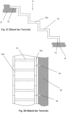
- the Figures 27 and 28 shows the supporting body 12 of a staircase, using a two-stringer staircase as an example, which extends from a floor B to a ceiling D in a highly schematic representation.
- the supporting body 12 essentially consists of two supporting parts 12a, 12b, which can for example consist of welded steel profiles, and connecting webs 13, which connect the two supporting parts 12a, 12b to one another.
- the supporting body 12 stands at its lower end on a section of a floor B of the building and rests at its upper end on a ceiling D, so that an upper and a lower connection are formed.
- supporting elements 16 extend from the supporting body 12 and form the supporting body-side connections. These each extend into holes or recesses in the wall W, which form the matching building-side connections.
- the supporting body 12 is prefabricated and is installed in the building in a prefabricated state.
- tread elements 20 are arranged on the steps of the supporting body 12, as shown in the Figures 29 and 30 As can be seen from the Figure 31 the tread elements 20 are fixed to the supporting body by means of fastening bolts 60 and nuts 62 12. It is previously known to arrange rubber elements for shell decoupling between each step element 40 and the supporting body 12.
- the Figure 1 shows an inventive improvement of the Figure 31 Shown in one of the Figure 31 corresponding representation.
- the tread element 20 of the Figure 31 replaced by a step element 40, which consists of at least 3 elements, namely a support 42, which in the embodiment shown is trough-shaped, a decoupling element 44 and a tread element 20.
- the trough-shaped support 42 can be made of sheet steel and has a front wall 42a, a rear wall 42b, side walls 42c, and a base plate 42d.
- fastening bolts 60 extend from the base plate 42d, which are secured to the support body 12 with nuts 62. If other types of connection between the support body 12 and support 42 are selected, for example welding or direct screwing, the fastening bolts 60 can of course be omitted.
- a trough-shaped design of the support 42 is generally clearly preferred for reasons of inherent rigidity, embodiments are also conceivable in which the support 42 consists exclusively of the base plate 42d.
- elastic elements can be arranged between the carrier 42 and the support body 12 and/or between the nuts 62 and the support body 12 (not shown).
- a decoupling element 44 is provided.
- This decoupling element 44 preferably has a dynamic stiffness between 5 and 50 MN/ m3 and can, in particular, be a panel made of mineral wool, polystyrene, or a wood fiber material.
- the underside of the decoupling element is fully bonded to the base plate 42d.
- a residually elastic adhesive such as a bitumen adhesive, is used as the adhesive, which additionally dampens the sound of the sheet metal tray.
- the decoupling element 44 supports the tread element 20 on its upper side and is also connected to it, in particular by full-surface bonding, for which a residually elastic adhesive can also be used.
- the tread element 20 rests almost entirely on the decoupling element 44, so that it does not have to absorb any bending stresses or the like. Accordingly, the material of the tread element 20 can be selected almost arbitrarily; it can be, for example, a tile, a piece of parquet, a thin stone slab, a relatively thin wooden board, or the like.
- the full-surface bonding greatly reduces the vibrational capacity of the tread element, and sound energy is diverted into the decoupling element.
- the Figure 4 shows (in greater detail) another embodiment of a step element 40, which is similar to the step element of the Figures 2 and 3 .
- the differences to Figure 3 The following are the advantages of the embodiment shown:
- the step element 20 is somewhat shorter so that it has no overhang.
- the front wall 42a of the trough-like support 42 is designed with a lower height than the rear wall 42b.
- parallel stiffening ribs 41 are provided, which extend from the base plate 42d.
- This provides several "parallel-connected" decoupling elements 44, each of which is fully connected with its upper and lower sides to the base plate 42d or are glued to the tread element 20 (adhesive layers 46, 47). Silicone joints 56 are used for sealing.
- the tread element 20 is designed in two layers, namely it consists of a visible upper layer 20a and a concealed intermediate layer 20b.
- the upper layer 20a can be made of tiles, stone, or parquet, for example.
- the intermediate layer is a screed layer poured directly onto the decoupling element.
- Lateral decouplings 58 which can be made of silicone, serve for lateral formwork.
- the upper layer 20a can be applied to the still-damp screed, creating a material-to-material bond. Subsequent gluing is also possible, however. It is also possible to manufacture the tread element exclusively from screed (which can also be colored), so that it is visible.
- a residually elastic adhesive layer is preferably provided between the decoupling element and the base plate.
- the Figure 4b shows a further variation.
- no intermediate layer is provided, but this would also be possible here.
- the essential difference to the examples of Figures 4 and 4a consists in the provision of two different decoupling elements, namely at least one front decoupling element 44a and at least one rear decoupling element 44b.
- the rear decoupling elements 44b can be designed as just described, while the front decoupling element 44a has a greater dynamic stiffness than the rear decoupling elements 44b.
- the front decoupling element can in particular be a cut from a rubber chip mat, although other materials are of course also possible.
- the decoupling elements 44a, 44b can also be screwed to the support 42 so that they are preloaded against the support. This also results in the desired sound deadening effect.
- the screws used for this purpose must, of course, not extend into the tread element 20. Such screwing is, of course, also possible when only one decoupling element or only one type of decoupling element is provided, as well as when an additional intermediate layer is provided.
- the supporting body 12 is also connected to the wall W.
- lateral supporting body-side connections 16 extend horizontally into the wall W.
- the corresponding building-side connection has elements filled with granulate, which surround the section of the supporting body-side connection projecting into the wall at least radially, preferably (as shown) on all sides (i.e. also on the front side), thus forming a sleeve.
- the granulate-filled elements 22, which are arranged radially, are designed as individual tubes. In the illustrated embodiment, the granulate-filled elements 22 are held in a sleeve-like enclosure 23.
- the lateral elements 22 filled with granulate can also be plate-shaped, so that the sleeve formed has a square cross-section.
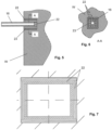
- a support-body-side connection (in this case preferably all staircase-side connections) can be designed as a pipe 100 - in particular made of steel - filled with granulate 31.
- the tube 100 encloses a cavity filled with granules, which is closed on both sides by an end piece 102, 104.
- the granules used here are, in particular, quartz sand, but also steel granules (steel sand), or a mixture thereof.
- the granulate preferably fills the entire cavity between the end pieces 102, 104 and is further preferably slightly compacted.
- the first end piece 102 is attached to one end face of the pipe, for example, by welding, and then the granulate 31 is filled into the standing pipe and compacted by vibration if necessary.
- the second end piece 104 whose outer diameter essentially corresponds to the inner diameter of the pipe 100, is pressed onto the granulate and then fixed to the pipe 100 (for example, also by welding).
- the granulate filled cavity does not necessarily extend over the entire length of the tube 100.
- the tube can have a round or a square cross-section.
- At least one sound diffuser can be provided, which is in mechanical contact with both the tube 100 and/or at least one of the end pieces 102, 104 and the granulate.
- such sound diffusers can be designed, for example, in the form of lamellae 106, wires, or the like extending from the inner wall of the pipe.
- Steel wool 108 which was introduced into the pipe before it was filled with granules, can also be used as a sound diffuser ( Figure 10 ).
- the sound diffuser should always be made of metal, especially the same as the pipe 100 (usually steel), to ensure good sound transmission and also to prevent corrosion.
- Such a pipe filled with granulate can serve as a lateral support body connection, but - as described in more detail below - can also form an upper or lower support body connection or a part of such.
- FIG. 11 shows an embodiment for the connection of the upper end of the support body 12 to a ceiling D (the connection of the lower end to a floor or a suspended ceiling can be carried out in the same way).
- the support body-side connection is formed by a section of the support body 12 itself, namely by an end surface. This is located directly or indirectly on a granulate-filled element 22, which in turn rests directly or indirectly on the ceiling D.
- granulate-filled elements can also be provided, one on top of the other. In the illustrated embodiment, three granulate-filled elements 22 are provided.
- Fixing is achieved via two sets of screws, namely first screws 52a, which connect the lowest of the granulate-filled elements 22 to the ceiling D, and second screws 52b, which connect the supporting body 12 to the uppermost granulate-filled element 22.
- the first and second screws must not touch each other in order to prevent direct sound transmission.
- the second screws 52b are preferably self-tapping screws, whereby a high extraction force and good sealing against granulate leakage can be achieved.
- the granulate-filled elements are preferably glued to one another. As can be seen, here too the frictional connection is achieved exclusively via the granulate of the granulate-filled elements.
- the granulate-filled elements or the interconnected, particularly screwed, packages of these elements should have a waterproof outer shell (not shown in the figures).
- a waterproof outer shell (not shown in the figures).
- This can be a paint/varnish or a plastic film.
- a cover should then be provided to protect against later (accidental) water penetration.
- the supporting body 12 By screwing the lowest element 22 filled with granulate to the building (here the ceiling) and by screwing the supporting body 12 to the uppermost element 22 filled with granulate, the supporting body 12 is secured against lateral displacement and against lifting off upwards.
- the supporting body could, as in Figure 11 shown, be directly screwed to the upper of the two elements filled with granulate, but in the embodiment shown a different approach is taken:
- the support body-side connection has a tube filled with granulate and preferably at least one sound diffuser, as described with reference to the Figures 8 to 10 described above, and a force transmission plate 112 adjoining it, which can be identical to the first end piece 102.
- sound absorption occurs in the support-side connection and in the building-side connection.
- improved sound insulation compared to the state of the art could already be achieved with one of the two measures mentioned, but the "in-series connection" shown is ideal.
- the Figure 13 shows a variation of what has just been described, in which the supporting body of the staircase is even better secured against lateral displacement and lifting forces.
- a tensioning device here in the form of a hood 114, is provided, which presses indirectly from above onto the force transmission plate 112.
- the force connection takes place via at least one elastic sound decoupling element 116 and/or via at least one element 22 filled with granulate.
- the element 22 filled with granulate lies directly on the force transmission plate 112, so that it can introduce sound from both surfaces for dissipation into a granulate-filled element 22.
- elastic washers 118 can be arranged under the fastening points.
- the illustrated embodiment has the advantage that the granulate-filled elements 22 are essentially protected from all sides and that nothing needs to be screwed into them.
- several tension straps or clamps can also be provided as tensioning devices.
- the Figure 14 shows a variation to the one in Figure 13 Shown.
- the lower elements filled with granulate are enclosed at the bottom and sides by a trough-like, force-absorbing enclosure element 120, so that no granulate can escape laterally and settlement of the stairs is prevented.
- the enclosure element can be made, in particular, of sheet steel.
- the force transmission plate has a smaller area than the free cross-section of the enclosure element, so that direct (and thus sound-transmitting) contact between the force transmission plate 112 and the enclosure element 120 is excluded. In this case, it would also be possible in principle to fill the enclosure element 120 directly with the granulate. In this case, it is recommended to seal the joint between the force transmission plate 112 and the enclosure element with an elastic material such as silicone.
- the granulate of the building-side connection is accommodated in a recess in the building (floor or ceiling) designed as a trough.
- a recess in the building floor or ceiling
- connection on the supporting body side and the connection on the building side form a connection unit.
- the Figure 16 shows an application of one aspect of the invention to a staircase whose supporting body 12 is made of concrete or reinforced concrete.
- each landing has a recess 24 in which at least one decoupling element 44 is accommodated, which, as with reference to Figures 4 , 4a
- This decoupling element 44 directly or indirectly supports the tread element 20, so that the effect is as described above.
- the tread element 20 is not in direct contact with the support body 12.
- a seal for example made of silicone, can also be provided here.
- the Figure 17 shows an alternative to the Figure 9
- step elements 40 as they are shown with reference to the Figures 2 to 4a described, arranged on the shoulders of the supporting body 12 and force-fitted to the supporting body 12 made of concrete or reinforced concrete.
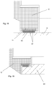
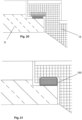
- these connections be designed such that the building-side connections have at least one element 22 filled with granulate, through which the frictional connection is established. Examples of a lower connection are shown in the Figures 18 and 19 shown, an example of an upper connection is shown in Figure 20 shown.
- an elastic element 48 is provided below the at least one granulate-filled element 22. This may often be preferred, but is not always mandatory.
- the granulate-filled elements 22 are accommodated in a recess of the supporting body 12.
- the supporting body itself can absorb lateral forces, so that the granulate-filled elements, whose casings are usually made of cardboard or a similar non-rigid material, can also be used in supports for heavy concrete or reinforced concrete stairs.
- an enclosure element 120 may be provided alternatively or additionally. This applies to both the upper and lower end supports.
- a cavity can also extend into the wall or floor of the housing, in which the granulate (which here can also be in the form of an element filled with granulate or in the form of a sand bed) is arranged, thus preventing lateral escape.
- the granulate which here can also be in the form of an element filled with granulate or in the form of a sand bed
- an additional enclosure element can be provided.
- the lateral enclosure (enclosure) (by the supporting structure, by the building or by a separate enclosure element) is even more important than in the case of a lightweight staircase.
- a connection in particular a lateral connection, can be made via a pin-shaped support-body-side connection 16, which extends laterally from the support body 12.
- a pin-shaped support-body-side connection 16 which extends laterally from the support body 12.
- the seal 56 can be a foam.
- the seal does not contribute to force exclusion.
- an enclosure element 120 should also be provided here.
- At least some of the elements 22 filled with granulate can also be used as in the Figures 25 and 26
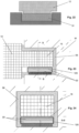
- This element has a structural body made of an elastic material, through which at least one cavity (usually several cavities) filled with granules extends. The end faces are closed with closures.
- An element with this structure could be installed horizontally (with horizontally extending cavities) or vertically (with vertically extending cavities).
- the force connection is partially (usually predominantly) provided by the granules, although part of the force connection can also be provided via the structural body, with its elasticity ensuring that part of the force connection is provided via the granules, which is necessary to transfer the sound energy to be dissipated into them.
- the outer shell of the granule-filled element 22 is "inherently" waterproof.
- Such a granule-filled element 22 could (although this is not considered ideal based on current knowledge) also serve as a decoupling element 44 or as part of such a decoupling element.
- damping is provided both in the area of the tread elements and in the area of the building connections, but this is not mandatory.
- step elements such as those found in Figures 1 to 4a described, and/or the use of pipes filled with granulate in the area of the connections brings about a significant improvement in the acoustic properties.
- the Figures 32 and 33 show the application of the invention to a single step, in which a single step element 18 is connected by means of support elements 16 with a Wall W.
- the single step element 18 can be used as a step element as shown in the Figures 2 to 4a described, or it can be a conventional single step element made of wood.
- the connection of the supporting elements 16 to the wall is carried out as above with reference to the Figures 5 to 7 described.
- connection points of a railing to the supporting structure and/or the casing. This can be achieved, in particular, by using elastic, sound-decoupling elements or by using pipes filled with granulate, as described in detail.
Landscapes
- Engineering & Computer Science (AREA)
- Architecture (AREA)
- Civil Engineering (AREA)
- Structural Engineering (AREA)
- Steps, Ramps, And Handrails (AREA)
- Buildings Adapted To Withstand Abnormal External Influences (AREA)
Applications Claiming Priority (6)
| Application Number | Priority Date | Filing Date | Title |
|---|---|---|---|
| DE202018103574 | 2018-06-25 | ||
| DE102018117105 | 2018-07-16 | ||
| DE102018123135 | 2018-09-20 | ||
| DE202019101598.5U DE202019101598U1 (de) | 2018-06-25 | 2019-03-20 | In einem Gebäude eingebaute Treppe, mit Granulat gefülltes Element, Treppe zum Einbau in ein Gebäude, Stufenelement und in einem Gebäude eingebaute Einzelstufe |
| PCT/EP2019/066635 WO2020002209A1 (fr) | 2018-06-25 | 2019-06-24 | Escalier installé dans un immeuble, élément rempli de granulat, escalier pour installation dans un immeuble, élément d'étage et étage individuel installé dans un immeuble |
| EP19734027.6A EP3810865B1 (fr) | 2018-06-25 | 2019-06-24 | Escalier pour installation dans un immeuble et élément d'étage |
Related Parent Applications (1)
| Application Number | Title | Priority Date | Filing Date |
|---|---|---|---|
| EP19734027.6A Division EP3810865B1 (fr) | 2018-06-25 | 2019-06-24 | Escalier pour installation dans un immeuble et élément d'étage |
Publications (2)
| Publication Number | Publication Date |
|---|---|
| EP4553246A2 true EP4553246A2 (fr) | 2025-05-14 |
| EP4553246A3 EP4553246A3 (fr) | 2025-08-13 |
Family
ID=68276785
Family Applications (2)
| Application Number | Title | Priority Date | Filing Date |
|---|---|---|---|
| EP25159740.7A Pending EP4553246A3 (fr) | 2018-06-25 | 2019-06-24 | Escalier destiné à être installé dans un bâtiment et élément de marche |
| EP19734027.6A Active EP3810865B1 (fr) | 2018-06-25 | 2019-06-24 | Escalier pour installation dans un immeuble et élément d'étage |
Family Applications After (1)
| Application Number | Title | Priority Date | Filing Date |
|---|---|---|---|
| EP19734027.6A Active EP3810865B1 (fr) | 2018-06-25 | 2019-06-24 | Escalier pour installation dans un immeuble et élément d'étage |
Country Status (3)
| Country | Link |
|---|---|
| EP (2) | EP4553246A3 (fr) |
| DE (1) | DE202019101598U1 (fr) |
| WO (1) | WO2020002209A1 (fr) |
Family Cites Families (8)
| Publication number | Priority date | Publication date | Assignee | Title |
|---|---|---|---|---|
| US3875708A (en) * | 1973-11-23 | 1975-04-08 | Selvaagebygg As | Arrangement for stairs of concrete for attainment of reduced step noise |
| DE3020142A1 (de) * | 1980-05-27 | 1981-12-03 | Friedrich 7250 Leonberg Eger | Schallisolierende lagerung von trittplatten bei treppen |
| DE3105646A1 (de) * | 1981-02-17 | 1982-08-26 | Hans 7341 Amstetten Bäumler | Geschosstreppe |
| DE3801732A1 (de) * | 1988-01-21 | 1989-07-27 | Mantel Juval | Schall-isolier-folie und wickelfolie fuer rohre und kanaele |
| EP0685613B1 (fr) * | 1994-06-03 | 1999-02-10 | Nivo AG | Dispositif de reprise et de transfert d'efforts tranchants entre deux éléments de construction |
| DE29920844U1 (de) * | 1999-11-29 | 2000-05-25 | NEUCON Maschinen- und Bausysteme G.m.b.H. u. Co. Kommanditgesellschaft, 74076 Heilbronn | Freitragende Treppe |
| DE102007019023B4 (de) * | 2007-04-17 | 2009-02-26 | Nützel, Bernd | Schallentkoppelndes Auflager |
| DE102014113635A1 (de) * | 2014-09-22 | 2016-03-24 | Max Frank Gmbh & Co. Kg | Bauelement zum Verbinden von zwei durch eine Fuge getrennten Gebäudeteilen |
-
2019
- 2019-03-20 DE DE202019101598.5U patent/DE202019101598U1/de active Active
- 2019-06-24 EP EP25159740.7A patent/EP4553246A3/fr active Pending
- 2019-06-24 WO PCT/EP2019/066635 patent/WO2020002209A1/fr not_active Ceased
- 2019-06-24 EP EP19734027.6A patent/EP3810865B1/fr active Active
Also Published As
| Publication number | Publication date |
|---|---|
| DE202019101598U1 (de) | 2019-09-27 |
| EP3810865A1 (fr) | 2021-04-28 |
| EP3810865B1 (fr) | 2025-02-26 |
| WO2020002209A1 (fr) | 2020-01-02 |
| EP3810865C0 (fr) | 2025-02-26 |
| EP4553246A3 (fr) | 2025-08-13 |
Similar Documents
| Publication | Publication Date | Title |
|---|---|---|
| EP3202567B1 (fr) | Procédé de production d'un composite bois/béton comme élément de construction | |
| AT522516B1 (de) | Raum-Modul, aus Raum-Modulen hergestelltes Gebäude, sowie jeweils ein Herstellverfahren hierfür | |
| EP3272961A1 (fr) | Élément de recouvrement en bois | |
| WO2014053070A1 (fr) | Kit pour réaliser une structure porteuse | |
| EP3543416B1 (fr) | Élément de plafond bois-béton | |
| EP2481867B1 (fr) | Elément de montage dans des joints de séparation de bâtiments | |
| EP3810865B1 (fr) | Escalier pour installation dans un immeuble et élément d'étage | |
| EP3754125B1 (fr) | Élément de construction pour le montage dans des joints de dilatation de bâtiments | |
| EP3498929B1 (fr) | Module de bâtiment de construction en hauteur et bâtiment conçu à l'aide dudit module | |
| EP2626479B1 (fr) | Elément de construction pour le montage dans des joints de dilatation de bâtiments | |
| DE2721799A1 (de) | Sparrenloses gebaeude bzw. sparrenloser teil eines gebaeudes | |
| DE10227327B4 (de) | Geschoßdecke | |
| WO1997013043A1 (fr) | Maison prefabriquee de construction en dur et modulaire | |
| AT522177B1 (de) | Sockel für eine Holzwand | |
| DE202007013392U1 (de) | Schalldämmmatte für ein körperschalldämmendes Wandlager zur schwingungstechnischen Entkopplung einer Bodenplatte und einer darauf errichteten Wand | |
| DE19745783A1 (de) | Holzsystemhaus | |
| EP3543414A1 (fr) | Isolation à base de fibre naturelle, partie de bâtiment pourvue d'isolation à base de fibre naturelle et l'utilisation d'isolation à base de fibre naturelle | |
| DE20318689U1 (de) | Holzbauelement | |
| EP3130718A1 (fr) | Élement composite de construction | |
| AT18619U1 (de) | Lärmschutzwand | |
| DE7906092U1 (de) | Schallgedaemmte treppe zum einbau in bauwerke | |
| DE202010010403U1 (de) | Konstruktionsstütze für körperschallrelevante Aufbauten | |
| DE202019103003U1 (de) | Raum-Modul sowie ein aus Raum-Modulen hergestelltes Gebäude | |
| DE8201876U1 (de) | Nasszelle mit einem fussbodenelement | |
| DE1888368U (de) | Vorgefertigtes plattenförmiges, entsprechend der Geschoßhöhe oder Spannweite bemessenes Wand- oder Decken-Bauelement für den Hausbau |
Legal Events
| Date | Code | Title | Description |
|---|---|---|---|
| PUAI | Public reference made under article 153(3) epc to a published international application that has entered the european phase |
Free format text: ORIGINAL CODE: 0009012 |
|
| STAA | Information on the status of an ep patent application or granted ep patent |
Free format text: STATUS: THE APPLICATION HAS BEEN PUBLISHED |
|
| AC | Divisional application: reference to earlier application |
Ref document number: 3810865 Country of ref document: EP Kind code of ref document: P |
|
| AK | Designated contracting states |
Kind code of ref document: A2 Designated state(s): AL AT BE BG CH CY CZ DE DK EE ES FI FR GB GR HR HU IE IS IT LI LT LU LV MC MK MT NL NO PL PT RO RS SE SI SK SM TR |
|
| REG | Reference to a national code |
Ref country code: DE Ref legal event code: R079 Free format text: PREVIOUS MAIN CLASS: E04F0011104000 Ipc: E04F0011025000 |
|
| PUAL | Search report despatched |
Free format text: ORIGINAL CODE: 0009013 |
|
| AK | Designated contracting states |
Kind code of ref document: A3 Designated state(s): AL AT BE BG CH CY CZ DE DK EE ES FI FR GB GR HR HU IE IS IT LI LT LU LV MC MK MT NL NO PL PT RO RS SE SI SK SM TR |
|
| RIC1 | Information provided on ipc code assigned before grant |
Ipc: E04F 11/025 20060101AFI20250704BHEP Ipc: E04F 11/04 20060101ALI20250704BHEP Ipc: E04F 11/104 20060101ALI20250704BHEP |
|
| STAA | Information on the status of an ep patent application or granted ep patent |
Free format text: STATUS: REQUEST FOR EXAMINATION WAS MADE |
|
| 17P | Request for examination filed |
Effective date: 20260213 |