EP4553257A1 - Tour de transport d'énergie - Google Patents
Tour de transport d'énergie Download PDFInfo
- Publication number
- EP4553257A1 EP4553257A1 EP24801062.1A EP24801062A EP4553257A1 EP 4553257 A1 EP4553257 A1 EP 4553257A1 EP 24801062 A EP24801062 A EP 24801062A EP 4553257 A1 EP4553257 A1 EP 4553257A1
- Authority
- EP
- European Patent Office
- Prior art keywords
- arcing
- voltage end
- insulator
- fitting
- plate
- Prior art date
- Legal status (The legal status is an assumption and is not a legal conclusion. Google has not performed a legal analysis and makes no representation as to the accuracy of the status listed.)
- Pending
Links
Images

Classifications
-
- H—ELECTRICITY
- H01—ELECTRIC ELEMENTS
- H01B—CABLES; CONDUCTORS; INSULATORS; SELECTION OF MATERIALS FOR THEIR CONDUCTIVE, INSULATING OR DIELECTRIC PROPERTIES
- H01B17/00—Insulators or insulating bodies characterised by their form
- H01B17/14—Supporting insulators
-
- E—FIXED CONSTRUCTIONS
- E04—BUILDING
- E04H—BUILDINGS OR LIKE STRUCTURES FOR PARTICULAR PURPOSES; SWIMMING OR SPLASH BATHS OR POOLS; MASTS; FENCING; TENTS OR CANOPIES, IN GENERAL
- E04H12/00—Towers; Masts or poles; Chimney stacks; Water-towers; Methods of erecting such structures
- E04H12/24—Cross arms
-
- H—ELECTRICITY
- H02—GENERATION; CONVERSION OR DISTRIBUTION OF ELECTRIC POWER
- H02G—INSTALLATION OF ELECTRIC CABLES OR LINES, OR OF COMBINED OPTICAL AND ELECTRIC CABLES OR LINES
- H02G7/00—Overhead installations of electric lines or cables
- H02G7/04—Arrangements or devices for relieving mechanical tension
-
- H—ELECTRICITY
- H02—GENERATION; CONVERSION OR DISTRIBUTION OF ELECTRIC POWER
- H02G—INSTALLATION OF ELECTRIC CABLES OR LINES, OR OF COMBINED OPTICAL AND ELECTRIC CABLES OR LINES
- H02G7/00—Overhead installations of electric lines or cables
- H02G7/05—Suspension arrangements or devices for electric cables or lines
-
- H—ELECTRICITY
- H02—GENERATION; CONVERSION OR DISTRIBUTION OF ELECTRIC POWER
- H02G—INSTALLATION OF ELECTRIC CABLES OR LINES, OR OF COMBINED OPTICAL AND ELECTRIC CABLES OR LINES
- H02G7/00—Overhead installations of electric lines or cables
- H02G7/20—Spatial arrangements or dispositions of lines or cables on poles, posts or towers
Definitions
- the present application relates to the field of power transmission technologies, and in particular, to a transmission tower.
- a node fitting In a transmission tower, a node fitting is generally used for connecting insulators and attaching a conductor.
- the existing node fitting has a complex structure, occupies a large space, and thus is not conducive to construction and maintenance, and on the other hand, in order to guarantee safety under extreme working conditions, overlarge design redundancy is set for the node fitting, thus reducing an economy.
- the present application provides a transmission tower, in which a node fitting can have a simple structure, be easy to manufacture, have clear force transmission, be matched with any conductor bundle number and any wire attaching point number, and meanwhile have a good bending moment resisting capacity.
- a transmission tower including: a tower body; and a composite crossarm arranged on the tower body.
- the composite crossarm includes: a post insulator having a low-voltage end connected to the tower body, and a high-voltage end; a suspension insulator having a low-voltage end connected to the tower body, and a high-voltage end; and a node fitting comprising two clamping plates arranged parallel to each other.
- the high-voltage end of the post insulator and the high-voltage end of the suspension insulator are connected together by the node fitting, and the post insulator and the suspension insulator are inserted between the two clamping plates through connecting fittings, so that the post insulator and the suspension insulator are connected to the node fitting, and each of the two clamping plates is provided with a wire attaching hole for attaching a conductor.
- the high-voltage end of the post insulator is provided with a first connecting fitting
- the first connecting fitting includes: a flange cylinder axially formed as a hollow structure; a sealing plate configured to seal an end of the flange cylinder away from the post insulator; and an insertion plate arranged on a side of the sealing plate away from the flange cylinder, and being perpendicular to the sealing plate.
- a first connecting hole is formed in the insertion plate, each of the two clamping plates is provided with a second connecting hole, the insertion plate is inserted between the two clamping plates, and a fastener is inserted into the first connecting hole and the second connecting hole that are aligned with each other, so as to fixedly connect the first connecting fitting to the node fitting.
- the high-voltage end of the suspension insulator is provided with a second connecting fitting
- the second connecting fitting is a plate member
- the second connecting fitting is provided with a third connecting hole
- each of the two clamping plates is provided with a fourth connecting hole
- the second connecting fitting is inserted between the two clamping plates, and a fastener is inserted into the third connecting hole and fourth connecting hole aligned with each other, so as to fixedly connect the second connecting fitting to the node fitting.
- a high-voltage end of the composite crossarm is provided with a high-voltage end arcing assembly
- a low-voltage end of the composite crossarm is provided with a low-voltage end arcing assembly
- the high-voltage end arcing assembly and the low-voltage end arcing assembly form a shortest electric clearance on the composite crossarm.
- the high-voltage end arcing assembly includes a first arcing ball and a first arcing bar, the first arcing bar has an end connected to the high-voltage end of the composite crossarm and another end connected to the first arcing ball, and the first arcing ball is used as an arcing end of the high-voltage end arcing assembly.
- the low-voltage end arcing assembly includes a first arcing ring and a second arcing bar, the first arcing ring is provided with a first notch, the second arcing bar has an end connected to the first arcing ring at the first notch and another end bending in a direction away from the first arcing ring, and an end of the second arcing bar away from the first arcing ring is used as an arcing end of the low-voltage end arcing assembly.
- the high-voltage end arcing assembly includes a second arcing ring, a second arcing ball, and a connecting bracket, the second arcing ring and the second arcing ball are connected to the composite crossarm through the connecting bracket, the second arcing ring is provided with a second notch, and the second arcing ball is located at the second notch to serve as the arcing end of the high-voltage end arcing assembly.
- the transmission tower further includes: a first hinged member configured to connect the low-voltage end of the post insulator to the tower body, so that the post insulator is rotatable relative to the tower body; and a second hinged member configured to connect the low-voltage end of the suspension insulator to the tower body, so that the suspension insulator is rotatable relative to the tower body.
- the tower body includes: a tower main body; a first support frame and a second support frame.
- the first support frame and the second support frame are convexly arranged on a same side wall of the tower main body, the first support frame is connected to the low-voltage end of the post insulator, and the second support frame is connected to the low-voltage end of the suspension insulator.
- Each of two opposite outer plate surfaces of the two clamping plates is connected to a fixing plate, and the fixing plate is provided with a construction hole for construction and maintenance of the composite crossarm.
- Each of two opposite outer plate surfaces of the two clamping plates is connected to a fixing plate, the fixing plate is provided with an auxiliary connector, and the auxiliary connector is provided with a construction hole for construction and maintenance of the composite crossarm.
- the auxiliary connector is a T-shaped plate, and the auxiliary connector is detachably connected to the fixing plate.
- a reinforcing rib is arranged between the outer plate surface of the clamping plate and a first plate surface of the fixing plate, and another reinforcing rib is arranged between the outer plate surface of the clamping plate and a second plate surface of the fixing plate opposite to the first plate surface.
- the node fitting is formed by the two clamping plates, which not only meets use requirements, but also can make design of the node fitting more compact and avoid design redundancy. Meanwhile, compared with a node fitting formed by a single flat plate with a same total thickness, the node fitting in the present application has a larger section modulus around a neutral axis and a higher bending moment resisting capacity, thus prolonging service life of the node fitting.
- the composite crossarm can rotate relative to the tower body, so that excessive unbalanced tension can be released by rotation, and the tower body is protected from damage.
- the arrangement of the fixing plate and the auxiliary connector can facilitate operation, maintenance, and construction of the composite crossarm, and also ensure that the structure of the node fitting is free of interference and remains stable.
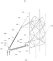
- the present application provides a transmission tower 10, including a tower body 100 and a composite crossarm 200 arranged on the tower body 100, and the composite crossarm 200 includes a post insulator 210, a suspension insulator 220, and a node fitting 230.
- the post insulator 210 has a low-voltage end connected to the tower body 100 and a high-voltage end.
- the suspension insulator 220 has a low-voltage end connected to the tower body 100 and a high-voltage end.
- the high-voltage ends of the post insulator 210 and the suspension insulator 220 are connected to the node fitting 230.
- the node fitting 230 connects the post insulator 210 and the suspension insulator 220 together to form an end of the composite crossarm 200 for attaching a conductor.
- the tower body 100 can be a transmission tower of a common structure, such as a lattice tower, a pole or a composite pole tower.
- the composite crossarm 200 can be arranged on one side of the tower body 100, or the composite crossarms 200 can be arranged on plural sides of the tower body 100.
- One composite crossarm 200 can be arranged on one side of the tower body 100, or plural composite crossarms 200 can be arranged at intervals in a vertical direction.
- the post insulator 210 includes an insulator body, a shed covering an outer circumference of the insulator body, and end fittings arranged at both ends of the insulator body, the insulator body is a composite insulator body made by impregnating glass fibers with epoxy resin, and the shed can be made of high temperature vulcanized silicone rubber, liquid silicone rubber, room temperature vulcanized silicone rubber, or the like, which is also not limited herein.
- a structure and a material of the suspension insulator 220 are similar to those of the post insulator 210 and not repeated.
- the post insulator 210 and the suspension insulator 220 are located on a same vertical line, and the low-voltage end of the suspension insulator 220 is higher than the low-voltage end of the post insulator 210.
- it is provided with two post insulators and two suspension insulators.
- it is provided with two post insulators and one suspension insulator.
- the numbers of the post insulators 210 and the suspension insulators 220 are not limited in the present application.
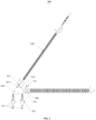
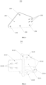
- the node fitting 230 includes two clamping plates 231 arranged parallel to each other.
- the clamping plate 231 is a plate member, such as a rectangular plate member, a circular plate member or other special-shaped plate member.
- the clamping plate 231 is a special-shaped plate member, specifically a polygonal plate member, which facilitates the connection to other members, and minimizes a size of a plate surface of the clamping plate 231 to reduce weight of the clamping plate 231, thereby reducing the weight of the node fitting 230 and a cost.
- the two parallel clamping plates 231 form the node fitting 230, a certain gap is reserved between the two clamping plates 231, and compared with a node fitting formed by a single flat plate with a same total thickness, the node fitting 230 according to the present application has a larger section modulus around a neutral axis of the node fitting 230 and a higher bending moment resisting capacity, thus prolonging service life of the node fitting 230.
- the post insulator 210 and the suspension insulator 220 are inserted between the two clamping plates 231 through connecting fittings, so that the post insulator 210 and the suspension insulator 220 are connected to the node fitting 230.
- the high-voltage end of the post insulator 210 is provided with a first connecting fitting 211 including a first flange cylinder 2111, a first sealing plate 2112, and a first insertion plate 2113.
- the first flange cylinder 2111 is axially formed as a hollow structure, an end of the insulator body of the post insulator 210 is sleeved by the first flange cylinder 2111, the first sealing plate 2112 seals an end of the first flange cylinder 2111 away from the post insulator 210 to prevent water vapor, or the like, from entering the insulator.
- the first insertion plate 2113 is arranged on a side of the first sealing plate 2112 away from the first flange cylinder 2111, and the first insertion plate 2113 is arranged perpendicular to the first sealing plate 2112.
- a plurality of first connecting holes 21131 are formed in the first insertion plate 2113, a plurality of second connecting holes 232 are formed in the two clamping plates 231, the number and positions of the first connecting holes 2113 are in one-to-one correspondence to the number and positions of the second connecting holes 232.
- the first insertion plate 2113 is inserted between the two clamping plates 231, the first connecting holes 21131 are aligned with the second connection holes 232 respectively, and a fastener is inserted into the first connecting holes 21131 and second connecting holes 232 aligned with each other, so as to fixedly connect the first connecting fitting 211 to the node fitting 230, and the post insulator 210 is fixedly connected to the node fitting 230.
- the plural post insulators may be first connected to the first connecting fittings of other structures, and then fixedly connected to the node fitting through the first connecting fittings, and details are not repeated.
- the high-voltage end of the suspension insulator 220 is provided with a second connecting fitting 221, the second connecting fitting 221 is a plate member, the second connecting fitting 221 is provided with a third connecting hole 2211, and each of the two clamping plates 231 is provided with a fourth connecting hole 233.
- the second connecting fitting 221 is inserted between the two clamping plates 231, and a fastener is inserted into the third connecting hole 2211 and the fourth connecting holes 233 aligned with each other, so as to fixedly connect the second connecting fitting 221 to the node fitting 230, and the suspension insulator 220 is fixedly connected to the node fitting 230.
- a connector when the number of the suspension insulators is at least two, a connector may be provided, the connector has an end fixedly connected to the node fitting 230 and another end fixedly connected to the plurality of suspension insulators, and details are not repeated.
- the second connecting hole 232 and the fourth connecting hole 233 are located at different ends of the clamping plate 231 to form a certain angle between the post insulator 210 and the suspension insulator 220, so that the post insulator, the suspension insulator 220, and the tower body 100 form a stable triangular structure to guarantee structural stability of the composite crossarm 200. Meanwhile, the node fitting 230 is stressed evenly, a concentrated force at a same position is avoided, and the service life of the node fitting 230 is prolonged.
- a wire attaching hole 234 is formed in a bottom of the clamping plate 231, a wire attaching fitting string 310 is directly attached in the wire attaching hole 234, and the wire attaching fitting string 310 is correspondingly provided with two clamps 311 for attaching two sub-conductors.
- the bottom of the clamping plate 231 is also provided with a first construction hole 235, and the first construction hole 235 is spaced apart from the wire attaching hole 234 and configured for construction or maintenance.
- single-phase quad-bundle is attached by the composite crossarm 200 of the transmission tower 10.
- two wire attaching holes 234 are spaced at the bottom of the clamping plate 231 to facilitate attaching of, for example, fitting strings with a double-attaching-point, double-string mode, and two sub-conductors are attached in each wire attaching hole 234.
- Two wire attaching holes 234 and one first construction hole 235 are arranged at intervals in a direction parallel to the bottom of the clamping plate 231, which can guarantee a force uniformity of the node fitting 230.
- the first construction hole 235 can be configured to attach the wire attaching fitting string 310, and the wire attaching hole 234 is configured for construction or maintenance; that is, functions of the wire attaching hole 234 and the first construction hole 235 can be exchanged.
- numbers of the wire attaching hole and the first construction hole can also be set to other numbers, as long as a wire attaching demand is met.
- the node fitting 230 in the present application has a simple structure, is convenient to manufacture and has a clear force transmission path and a simple force form.
- two first connecting plates 2114 are arranged on the first connecting fitting 211, the two first connecting plates 2114 are distributed on two sides of the first flange cylinder 2111 along an extension direction of the conductor, a temporary guy wire hole 21141 is formed in the first connecting plate 2114, and a guy wire can be arranged during mounting and wiring of the composite crossarm 200.
- two guy wires can be arranged and located on two sides of the post insulator 210 respectively, and each guy wire has an end connected to the first connecting fitting 211 through the temporary guy wire hole 21141 and another end connected to the tower body 100, so as to guarantee stability of the composite crossarm 200 in construction and mounting processes.
- the first connecting fitting 211 is further provided with a second connecting plate 2115 and a third connecting plate 2116, and the second connecting plate 2115 and the third connecting plate 2116 are distributed on the two sides of the first flange cylinder 2111 along a direction perpendicular to the extension direction of the conductor, that is, the second connecting plate 2115 and the third connecting plate 2116 are distributed on a top and a bottom of the first flange cylinder 2111, as shown in FIG. 4 .
- the two first connecting plates 2114, the second connecting plate 2115, and the third connecting plate 2116 are uniformly and circumferentially arranged on the first flange cylinder 2111.
- the second connecting plate 2115 is provided with a mounting hole for mounting an arcing device
- the third connecting plate 2116 is provided with a second construction hole for construction or maintenance.
- each of two opposite outer plate surfaces of the two clamping plates 231 of the node fitting 230 is connected to a fixing plate 236, and the fixing plate 236 is provided with a third construction hole for construction or maintenance of the composite crossarm 200.
- an auxiliary connector 237 is mounted on the fixing plate 236, the fixing plate 236 is connected to the auxiliary connector 237 by forming corresponding through holes in the fixing plate 236 and the auxiliary connector 237 and inserting a fastener in the through holes, and a third construction hole is formed in the auxiliary connector 237, so that other auxiliary devices for construction or maintenance of the composite crossarm 200 can be fixedly connected to the node fittings 230.
- the arrangement of the auxiliary connector 237 can avoid interference with the composite crossarm 200 when other auxiliary devices are directly mounted to the fixing plate 236, so that mounting can be conveniently and rapidly performed.
- the auxiliary connector 237 is a T-shaped plate, and the auxiliary connector 237 is detachably connected to the fixing plate 236 by bolts and nuts, so that the auxiliary connector 237 can be detached and reused.
- the third construction hole can be formed in the fixing plate or other components of the node fitting for directly connecting other auxiliary devices, which is not limited herein.
- reinforcing ribs 238 are arranged between the outer plate surface of the clamping plate 231 and two opposite plate surfaces of the fixing plate 236. That is, the two reinforcing ribs 238 are arranged between the plate surfaces on two sides at a fixed connection position of the clamping plate 231 and the fixing plate 236.
- the arrangement of the reinforcing rib 238 can further increase connection strength between the fixing plate 236 and the clamping plate 231, so that when other auxiliary devices are fixed on the node fitting 230, the phenomenon that other auxiliary devices fall off due to breakage of the fixing plate 236 can be avoided, and potential safety hazards are further eliminated.
- the clamping plate 231, the fixing plate 236, and the reinforcing ribs 238 can be separately formed and then connected by welding, or can be directly formed integrally, which is not limited herein.
- the high-voltage end of the post insulator 210 is sleeved by an end fitting 212, and the end fitting 212 is detachably connected to a third connecting fitting 213, so that the post insulator 210 can be conveniently detached and replaced, and operation and maintenance of the composite crossarm 200 are realized.
- the end fitting 212 includes a second flange cylinder and a second sealing plate, the second flange cylinder is axially formed as a hollow structure, an end of the insulator body of the post insulator 210 is sleeved by the second flange cylinder, and the second sealing plate seals an end of the second flange cylinder away from the post insulator 210 to prevent water vapor, or the like, from entering the insulator body.
- the third connecting fitting 213 includes a third sealing plate and a second insertion plate, and the second insertion plate is arranged perpendicular to the third sealing plate.
- a fastener is inserted into the second sealing plate and the third sealing plate that match each other correspondingly, so as to detachably and fixedly connect the end fitting 212 to the third connecting fitting 213.
- the second insertion plate is fixedly inserted between the two clamping plates 231, and the third connecting fitting 213 is fixedly connected to the node fitting 230, so that the post insulator 210 is fixedly connected to the node fitting 230.
- the arcing device is mounted on the composite crossarm 200, and specifically includes a high-voltage end arcing assembly and a low-voltage end arcing assembly, the high-voltage end arcing assembly is arranged at the high-voltage end of the composite crossarm, the low-voltage end arcing assembly is arranged at the low-voltage end of the composite crossarm, and the high-voltage end arcing assembly and the low-voltage end arcing assembly form a shortest electric clearance on the composite crossarm 200, so that in an overvoltage case, such as when struck by lightning, the discharge clearance between the high-voltage end arcing assembly and the low-voltage end arcing assembly is first broken down, which can avoid burning of any insulator on the composite crossarm 200 due to a high current flowing from the high-voltage end to the low-voltage end, thereby protecting the composite crossarm 200 and reducing potential safety hazards.
- the high-voltage end of the post insulator 210 is provided with a first high-voltage end arcing assembly 410
- the first high-voltage end arcing assembly 410 includes a first arcing ball 411 and a first arcing bar 412, an end of the first arcing bar 412 is connected to the high-voltage end of the post insulator 210, another end of the first arcing bar 412 is connected to the first arcing ball 411, and the first arcing ball 411 serves as an arcing end of the first high-voltage end arcing assembly 410.
- the first arcing ball 411 is used as the arcing end of the first high-voltage end arcing assembly 410, which can ensure that while arcing initiation is realized, a ball structure can decrease point discharge phenomenon to guarantee uniform distribution of an electric field.
- An end of the first arcing bar 412 not connected to the first arcing ball 411 is fixedly connected to the second connecting plate 2115, so that the first high-voltage end arcing assembly 410 is fixedly connected to the post insulator 210.
- the low-voltage end of the post insulator 210 is provided with a first low-voltage end arcing assembly 420
- the first low-voltage end arcing assembly 420 includes a first arcing ring 421 and a second arcing bar 422
- the first arcing ring 421 is provided with a first notch
- the second arcing bar 422 has an end connected to the first arcing ring 421 at the first notch and another end bending in a direction away from the first arcing ring 421.
- the end of the second arcing bar 422 bending in a direction away from the first arcing ring 421 is used as an arcing end of the first low-voltage end arcing assembly 420.
- the arcing end of the first low-voltage end arcing assembly 420 is only required to have arcing initiation function, and therefore, a free end of the second arcing bar 422 not connected to the post insulator 210 is used as the arcing end of the first low-voltage end arcing assembly 420.
- the first low-voltage end arcing assembly 420 is fixedly connected to the low-voltage end of the post insulator 210 by a connector (not shown).
- the high-voltage end of the suspension insulator 220 is provided with a second high-voltage end arcing assembly 430
- the second high-voltage end arcing assembly 430 includes a second arcing ring 431, a second arcing ball 432, and a connecting bracket 433, the second arcing ring 431 is connected to the second connecting fitting 221 through the connecting bracket 433, so that the second high-voltage end arcing assembly 430 is connected to the high-voltage end of the suspension insulator 220.
- the second arcing ball 432 is also connected to the suspension insulator 220 through the connecting bracket 433, the second arcing ring 431 is provided with a second notch, and the second arcing ball 432 is located at the second notch to serve as an arcing end of the second high-voltage end arcing assembly 430.
- the second arcing ball 432 is used as the arcing end of the second high-voltage end arcing assembly 430, which can ensure that while arcing initiation is realized, a ball structure can decrease point discharge phenomenon to guarantee uniform distribution of an electric field.
- the low-voltage end of the suspension insulator 220 is provided with a second low-voltage end arcing assembly 440, a structure of which is similar to that of the first low-voltage end arcing assembly 420 and not repeated.
- the high-voltage end of the post insulator 210 is further sleeved by a grading ring 240.
- the transmission tower 10 further includes a first hinged member 510 and a second hinged member 520, and both the first hinged member 510 and the second hinged member 520 are rotatable connectors.
- the first hinged member 510 is configured to connect the low-voltage end of the post insulator 210 to the tower body 100, so that the post insulator 210 can rotate relative to the tower body 100;
- the second hinged member 520 is configured to connect the low-voltage end of the suspension insulator 200 to the tower body 100, so that the suspension insulator 220 can rotate relative to the tower body 100.
- both numbers of the post insulators 210 and the suspension insulators 220 are one, and the post insulator 210, the suspension insulator 220, and the tower body 100 form a stable triangular structure.
- the composite crossarm 200 may be affected by a wind load and other factors, resulting in an unbalanced tension of the conductor, and in this case, the composite crossarm 200 may rotate to a side of the conductor with greater tension, so that a span of the conductors on two sides (a horizontal distance between wire attaching points of two adjacent transmission towers) and other parameters change. That is, a wire attaching end of the composite crossarm 200 is displaced.
- the composite crossarm 200 deflects to a certain position, the tension on the conductors on two sides reaches a new balance, so that the unbalanced tension is released, and safety of a power transmission line is improved.
- the design Since the design has the effect of releasing the unbalanced tension load to a certain extent, it can be considered to reduce a design specification in the design, and compared with a fixed connection, a design for small failure load condition can be adopted in the present application, so as to reduce a manufacturing cost.
- the post insulator 210 is usually connected to the tower body 100 in the form of a lap plate (including an insertion plate, or the like), the connection is actually between a fixed connection and a hinged connection, but in corresponding pressing stability calculation, for security reasons, the connection is often assumed as a hinged connection, and a boundary condition for the hinged connection is used, resulting in design redundancy.
- the connection between the post insulator 210 and the tower body 100, and the connection between the suspension insulator 220 and the tower body 100 are hinged connections, which is consistent with the boundary condition assumed in a stability calculation formula and can avoid the design redundancy.
- the composite crossarm and the tower body may also be connected by a fixed connector, and in this case, neither the post insulator nor the suspension insulator can rotate relative to the tower body.
- the tower body 100 includes a tower main body 110, a first support frame 120, and a second support frame 130.
- the first support frame 120 and the second support frame 130 are convexly arranged on a same side wall of the tower main body 110, the first support frame 120 is connected to the low-voltage end of the post insulator 210, and the second support frame 130 is connected to the low-voltage end of the suspension insulator 220.
- the first support frame 120 can be designed adaptively according to a relative position and angle between the post insulator 210 and the tower body 100
- the second support frame 130 can be designed adaptively according to a relative position and angle between the suspension insulator 220 and the tower body 100.
- the composite crossarm 200 and the tower body 100 can be conveniently and efficiently maintained; on the other hand, when plural composite crossarms 200 are arranged on the tower body 100, since a distance between the composite crossarm 200 and the tower body 100 can be adjusted by the first support frame 120 and the second support frame 130, sizes of the plural composite crossarms 200 can be consistent, thereby improving a production efficiency.
- first support frame and the second support frame can be omitted, and the post insulator and the suspension insulator can be directly mounted on the tower body.
- first support frame is mounted, the second support frame is omitted, and in this case, the post insulator is connected to the first support frame, and the suspension insulator is mounted directly on the tower body, which is not limited herein.
Landscapes
- Engineering & Computer Science (AREA)
- Architecture (AREA)
- Civil Engineering (AREA)
- Structural Engineering (AREA)
- Insulators (AREA)
Applications Claiming Priority (3)
| Application Number | Priority Date | Filing Date | Title |
|---|---|---|---|
| CN202322607473.5U CN221073700U (zh) | 2023-09-25 | 2023-09-25 | 输电塔 |
| CN202421784133.8U CN223119655U (zh) | 2024-07-25 | 2024-07-25 | 一种输电塔 |
| PCT/CN2024/109411 WO2025066542A1 (fr) | 2023-09-25 | 2024-08-02 | Tour de transport d'énergie |
Publications (2)
| Publication Number | Publication Date |
|---|---|
| EP4553257A1 true EP4553257A1 (fr) | 2025-05-14 |
| EP4553257A4 EP4553257A4 (fr) | 2025-09-17 |
Family
ID=93656044
Family Applications (1)
| Application Number | Title | Priority Date | Filing Date |
|---|---|---|---|
| EP24801062.1A Pending EP4553257A4 (fr) | 2023-09-25 | 2024-08-02 | Tour de transport d'énergie |
Country Status (3)
| Country | Link |
|---|---|
| EP (1) | EP4553257A4 (fr) |
| AU (1) | AU2024349080A1 (fr) |
| WO (1) | WO2025066542A1 (fr) |
Family Cites Families (10)
| Publication number | Priority date | Publication date | Assignee | Title |
|---|---|---|---|---|
| US8173904B1 (en) * | 2009-04-21 | 2012-05-08 | Pelco Products, Inc. | Post insulator blade adaptor |
| CN202996444U (zh) * | 2012-12-19 | 2013-06-12 | 陕西省电力公司规划评审中心 | 一种配置有均压环、屏蔽环的750kV 输电线路复合横担结构 |
| CN218069483U (zh) * | 2022-07-06 | 2022-12-16 | 江苏神马电力股份有限公司 | 一种招弧组件、绝缘子及复合横担 |
| CN218991090U (zh) * | 2022-07-06 | 2023-05-09 | 江苏神马电力股份有限公司 | 一种复合横担及输电塔 |
| CN116290991A (zh) * | 2023-03-22 | 2023-06-23 | 上海神马电力工程有限公司 | 一种横担组件及输电塔 |
| CN116136133A (zh) * | 2023-03-22 | 2023-05-19 | 上海神马电力工程有限公司 | 输电塔 |
| CN116378494A (zh) * | 2023-03-22 | 2023-07-04 | 上海神马电力工程有限公司 | 一种横担组件及输电塔 |
| CN116780443A (zh) * | 2023-06-09 | 2023-09-19 | 广东电网能源发展有限公司 | 节点金具及复合横担 |
| CN116780444A (zh) * | 2023-06-09 | 2023-09-19 | 广东电网能源发展有限公司 | 节点金具以及复合横担 |
| CN221073700U (zh) * | 2023-09-25 | 2024-06-04 | 上海神马电力工程有限公司 | 输电塔 |
-
2024
- 2024-08-02 WO PCT/CN2024/109411 patent/WO2025066542A1/fr active Pending
- 2024-08-02 EP EP24801062.1A patent/EP4553257A4/fr active Pending
- 2024-08-02 AU AU2024349080A patent/AU2024349080A1/en active Pending
Also Published As
| Publication number | Publication date |
|---|---|
| WO2025066542A1 (fr) | 2025-04-03 |
| EP4553257A4 (fr) | 2025-09-17 |
| AU2024349080A1 (en) | 2026-04-09 |
Similar Documents
| Publication | Publication Date | Title |
|---|---|---|
| US11322923B2 (en) | Overhead power distribution line | |
| EP4660397A1 (fr) | Ensemble traverse et tour de transmission de puissance | |
| EP3988741B1 (fr) | Structure de transformation d'énergie | |
| CA3032316C (fr) | Tour d'angle et tour angulaire et support de tension comprenant celui-ci | |
| EP3975352B1 (fr) | Structure de sous-station | |
| WO2025138428A1 (fr) | Tour haubanée | |
| EP4553257A1 (fr) | Tour de transport d'énergie | |
| EP4553256A1 (fr) | Tour de transmission d'energie | |
| CN221073700U (zh) | 输电塔 | |
| CN220539376U (zh) | 输电塔 | |
| CN119352840A (zh) | 一种复合横担及输电杆 | |
| CN220247780U (zh) | 输电塔 | |
| EP4553255A1 (fr) | Tour de transmission | |
| CN111864543B (zh) | 一种变电构架 | |
| CN111864546B (zh) | 一种变电构架 | |
| CN111864544B (zh) | 一种变电构架 | |
| CN107248718A (zh) | 一种分裂导线支撑过渡金具 | |
| CN221481573U (zh) | 拉线塔 | |
| CN207021637U (zh) | 一种分裂导线支撑过渡金具 | |
| CN223739104U (zh) | 一种复合横担及输电杆 | |
| CN213717567U (zh) | 耐张串、杆塔和变电站的门型架 | |
| CN219554424U (zh) | 转角不断连更换绝缘子专用工具 | |
| CN223434160U (zh) | 一种复合横担及输电杆 | |
| CA3284975A1 (fr) | Ensemble traverse et tour de transmission de puissance | |
| CN117211580A (zh) | 输电塔 |
Legal Events
| Date | Code | Title | Description |
|---|---|---|---|
| STAA | Information on the status of an ep patent application or granted ep patent |
Free format text: STATUS: UNKNOWN |
|
| STAA | Information on the status of an ep patent application or granted ep patent |
Free format text: STATUS: THE INTERNATIONAL PUBLICATION HAS BEEN MADE |
|
| PUAI | Public reference made under article 153(3) epc to a published international application that has entered the european phase |
Free format text: ORIGINAL CODE: 0009012 |
|
| STAA | Information on the status of an ep patent application or granted ep patent |
Free format text: STATUS: REQUEST FOR EXAMINATION WAS MADE |
|
| 17P | Request for examination filed |
Effective date: 20241112 |
|
| AK | Designated contracting states |
Kind code of ref document: A1 Designated state(s): AL AT BE BG CH CY CZ DE DK EE ES FI FR GB GR HR HU IE IS IT LI LT LU LV MC ME MK MT NL NO PL PT RO RS SE SI SK SM TR |
|
| A4 | Supplementary search report drawn up and despatched |
Effective date: 20250821 |
|
| RIC1 | Information provided on ipc code assigned before grant |
Ipc: E04H 12/00 20060101AFI20250814BHEP Ipc: H02G 7/00 20060101ALI20250814BHEP Ipc: H02G 7/05 20060101ALI20250814BHEP Ipc: H02G 7/20 20060101ALI20250814BHEP Ipc: H01B 17/42 20060101ALI20250814BHEP |