EP4553264A1 - Porte comprenant au moins un battant coulissant et un battant articulé - Google Patents
Porte comprenant au moins un battant coulissant et un battant articulé Download PDFInfo
- Publication number
- EP4553264A1 EP4553264A1 EP24211162.3A EP24211162A EP4553264A1 EP 4553264 A1 EP4553264 A1 EP 4553264A1 EP 24211162 A EP24211162 A EP 24211162A EP 4553264 A1 EP4553264 A1 EP 4553264A1
- Authority
- EP
- European Patent Office
- Prior art keywords
- sash
- rails
- safety system
- control element
- upright
- Prior art date
- Legal status (The legal status is an assumption and is not a legal conclusion. Google has not performed a legal analysis and makes no representation as to the accuracy of the status listed.)
- Granted
Links
Images


Classifications
-
- E—FIXED CONSTRUCTIONS
- E06—DOORS, WINDOWS, SHUTTERS, OR ROLLER BLINDS IN GENERAL; LADDERS
- E06B—FIXED OR MOVABLE CLOSURES FOR OPENINGS IN BUILDINGS, VEHICLES, FENCES OR LIKE ENCLOSURES IN GENERAL, e.g. DOORS, WINDOWS, BLINDS, GATES
- E06B3/00—Window sashes, door leaves, or like elements for closing wall or like openings; Layout of fixed or moving closures, e.g. windows in wall or like openings; Features of rigidly-mounted outer frames relating to the mounting of wing frames
- E06B3/32—Arrangements of wings characterised by the manner of movement; Arrangements of movable wings in openings; Features of wings or frames relating solely to the manner of movement of the wing
- E06B3/50—Arrangements of wings characterised by the manner of movement; Arrangements of movable wings in openings; Features of wings or frames relating solely to the manner of movement of the wing with more than one kind of movement
- E06B3/509—Arrangements of wings characterised by the manner of movement; Arrangements of movable wings in openings; Features of wings or frames relating solely to the manner of movement of the wing with more than one kind of movement where one of the sliding and rotating movements necessarily precedes the other
-
- E—FIXED CONSTRUCTIONS
- E05—LOCKS; KEYS; WINDOW OR DOOR FITTINGS; SAFES
- E05D—HINGES OR SUSPENSION DEVICES FOR DOORS, WINDOWS OR WINGS
- E05D15/00—Suspension arrangements for wings
- E05D15/48—Suspension arrangements for wings allowing alternative movements
-
- E—FIXED CONSTRUCTIONS
- E05—LOCKS; KEYS; WINDOW OR DOOR FITTINGS; SAFES
- E05D—HINGES OR SUSPENSION DEVICES FOR DOORS, WINDOWS OR WINGS
- E05D15/00—Suspension arrangements for wings
- E05D15/06—Suspension arrangements for wings for wings sliding horizontally more or less in their own plane
- E05D15/0604—Suspension arrangements for wings for wings sliding horizontally more or less in their own plane allowing an additional movement
-
- E—FIXED CONSTRUCTIONS
- E05—LOCKS; KEYS; WINDOW OR DOOR FITTINGS; SAFES
- E05D—HINGES OR SUSPENSION DEVICES FOR DOORS, WINDOWS OR WINGS
- E05D15/00—Suspension arrangements for wings
- E05D15/56—Suspension arrangements for wings with successive different movements
- E05D15/58—Suspension arrangements for wings with successive different movements with both swinging and sliding movements
-
- E—FIXED CONSTRUCTIONS
- E06—DOORS, WINDOWS, SHUTTERS, OR ROLLER BLINDS IN GENERAL; LADDERS
- E06B—FIXED OR MOVABLE CLOSURES FOR OPENINGS IN BUILDINGS, VEHICLES, FENCES OR LIKE ENCLOSURES IN GENERAL, e.g. DOORS, WINDOWS, BLINDS, GATES
- E06B3/00—Window sashes, door leaves, or like elements for closing wall or like openings; Layout of fixed or moving closures, e.g. windows in wall or like openings; Features of rigidly-mounted outer frames relating to the mounting of wing frames
- E06B3/32—Arrangements of wings characterised by the manner of movement; Arrangements of movable wings in openings; Features of wings or frames relating solely to the manner of movement of the wing
- E06B3/34—Arrangements of wings characterised by the manner of movement; Arrangements of movable wings in openings; Features of wings or frames relating solely to the manner of movement of the wing with only one kind of movement
- E06B3/42—Sliding wings; Details of frames with respect to guiding
- E06B3/46—Horizontally-sliding wings
- E06B3/4609—Horizontally-sliding wings for windows
- E06B3/4627—Horizontally-sliding wings for windows with the sliding wing flush closing or moving a considerable distance towards the opening when closing
-
- E—FIXED CONSTRUCTIONS
- E06—DOORS, WINDOWS, SHUTTERS, OR ROLLER BLINDS IN GENERAL; LADDERS
- E06B—FIXED OR MOVABLE CLOSURES FOR OPENINGS IN BUILDINGS, VEHICLES, FENCES OR LIKE ENCLOSURES IN GENERAL, e.g. DOORS, WINDOWS, BLINDS, GATES
- E06B3/00—Window sashes, door leaves, or like elements for closing wall or like openings; Layout of fixed or moving closures, e.g. windows in wall or like openings; Features of rigidly-mounted outer frames relating to the mounting of wing frames
- E06B3/32—Arrangements of wings characterised by the manner of movement; Arrangements of movable wings in openings; Features of wings or frames relating solely to the manner of movement of the wing
- E06B3/34—Arrangements of wings characterised by the manner of movement; Arrangements of movable wings in openings; Features of wings or frames relating solely to the manner of movement of the wing with only one kind of movement
- E06B3/42—Sliding wings; Details of frames with respect to guiding
- E06B3/46—Horizontally-sliding wings
- E06B3/4636—Horizontally-sliding wings for doors
- E06B3/4645—Horizontally-sliding wings for doors with the sliding wing flush closing or moving a considerable distance towards the opening when closing
-
- E—FIXED CONSTRUCTIONS
- E06—DOORS, WINDOWS, SHUTTERS, OR ROLLER BLINDS IN GENERAL; LADDERS
- E06B—FIXED OR MOVABLE CLOSURES FOR OPENINGS IN BUILDINGS, VEHICLES, FENCES OR LIKE ENCLOSURES IN GENERAL, e.g. DOORS, WINDOWS, BLINDS, GATES
- E06B3/00—Window sashes, door leaves, or like elements for closing wall or like openings; Layout of fixed or moving closures, e.g. windows in wall or like openings; Features of rigidly-mounted outer frames relating to the mounting of wing frames
- E06B3/32—Arrangements of wings characterised by the manner of movement; Arrangements of movable wings in openings; Features of wings or frames relating solely to the manner of movement of the wing
- E06B3/50—Arrangements of wings characterised by the manner of movement; Arrangements of movable wings in openings; Features of wings or frames relating solely to the manner of movement of the wing with more than one kind of movement
- E06B3/5054—Arrangements of wings characterised by the manner of movement; Arrangements of movable wings in openings; Features of wings or frames relating solely to the manner of movement of the wing with more than one kind of movement where the sliding and rotating movements are independent of each other
- E06B3/5072—Arrangements of wings characterised by the manner of movement; Arrangements of movable wings in openings; Features of wings or frames relating solely to the manner of movement of the wing with more than one kind of movement where the sliding and rotating movements are independent of each other the horizontal sliding wings having the possibility of an additional rotational movement
-
- E—FIXED CONSTRUCTIONS
- E06—DOORS, WINDOWS, SHUTTERS, OR ROLLER BLINDS IN GENERAL; LADDERS
- E06B—FIXED OR MOVABLE CLOSURES FOR OPENINGS IN BUILDINGS, VEHICLES, FENCES OR LIKE ENCLOSURES IN GENERAL, e.g. DOORS, WINDOWS, BLINDS, GATES
- E06B3/00—Window sashes, door leaves, or like elements for closing wall or like openings; Layout of fixed or moving closures, e.g. windows in wall or like openings; Features of rigidly-mounted outer frames relating to the mounting of wing frames
- E06B3/92—Doors or windows extensible when set in position
- E06B3/922—Doors or windows extensible when set in position with several wings opening horizontally towards the same side of the opening and each closing a separate part of the opening
-
- E—FIXED CONSTRUCTIONS
- E05—LOCKS; KEYS; WINDOW OR DOOR FITTINGS; SAFES
- E05D—HINGES OR SUSPENSION DEVICES FOR DOORS, WINDOWS OR WINGS
- E05D15/00—Suspension arrangements for wings
- E05D15/48—Suspension arrangements for wings allowing alternative movements
- E05D2015/485—Swinging or sliding movements
-
- E—FIXED CONSTRUCTIONS
- E05—LOCKS; KEYS; WINDOW OR DOOR FITTINGS; SAFES
- E05Y—INDEXING SCHEME ASSOCIATED WITH SUBCLASSES E05D AND E05F, RELATING TO CONSTRUCTION ELEMENTS, ELECTRIC CONTROL, POWER SUPPLY, POWER SIGNAL OR TRANSMISSION, USER INTERFACES, MOUNTING OR COUPLING, DETAILS, ACCESSORIES, AUXILIARY OPERATIONS NOT OTHERWISE PROVIDED FOR, APPLICATION THEREOF
- E05Y2900/00—Application of doors, windows, wings or fittings thereof
- E05Y2900/50—Application of doors, windows, wings or fittings thereof for vehicles
- E05Y2900/514—Application of doors, windows, wings or fittings thereof for vehicles for ships
Definitions
- the present invention relates to a door of the type comprising a frame, a first sash mounted at a first upright of the frame, and at least a second sash mounted slidable along rails arranged on cross-pieces of the frame. In the open position, the second sash overlaps the first sash.
- sliding doors are widely used, generally provided with glass, in order to allow for communication between the inner and outer spaces of boats.
- Sliding doors are greatly used particularly in boats such as yachts insofar as they allow for extensive communication between spaces. There is a need to further increase such communicability, thereby rendering the inner and outer spaces in the form of a single space.
- One object of this invention is to propose a door of the above-described type that is capable of satisfying the requirements cited above.
- a door comprising:
- the pack formed by the first sash and the second sliding sash(s) may be made to rotate about a vertical axis once it has been liberated from the presence of the rails, thereby in fact allowing the opening surrounded by the door frame to be almost completely cleared. This, consequently, makes it possible to eliminate practically every barrier between those spaces that are separated by the door in question.
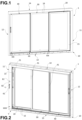
- FIG. 1 an example of a door, indicated as a whole with the numeral 1, is shown, made in the form of a glass door having three movable sashes, adapted to be mounted to a wall of a room of a boat.
- the view of Figure 1 is taken from an outer side of the door (intended as the outside of an environment delimited by the door), while the views of Figures 2-4 are taken from an inner side of the door (intended as the inside of the aforesaid environment).
- the expressions "inner side of the door” and “outer side of the door” are used for ease of presentation, and are not intended to be limiting.
- the door 1 comprises a main frame 10, adapted to be mounted to said wall (not shown) in such a way as to surround an opening formed in said wall.
- the main frame 10 comprises a pair of vertical elements or uprights 11, 12 and a pair of horizontal elements or cross-pieces 13, 14, interconnecting opposite ends of the uprights 11, 12.
- FIG. 13 Arranged on the cross-pieces 13, 14 are lower and upper rails 15, 16 for sliding sashes (a pair of rails for each sliding sash), configured to couple with corresponding sliding elements (not shown) integral with the sliding sashes.
- Figures 5 and 6 show the rails 15 arranged within the lower cross-piece 13. As may be seen, such rails 15 are movable vertically according to the direction indicated by the arrow A, between a forward position ( Figure 5 ) in which the rails 15 are able to engage the sliding sashes, and a retracted position ( Figure 6 ) in which the rails 15 do not interfere with the sliding sashes.
- the rails 15 protrude with respect to a top wall 13a of the lower cross-piece 13, extending through slots 13b formed in said top wall 13a.
- the rails 15 are retracted so as to have the top thereof inside the slots 13b.
- the rails 16 arranged within the upper cross-piece 14 have the same arrangement as described above.
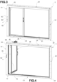
- the door 1 further comprises three movable sashes 20, 30, 40.
- the first of these sashes, indicated with 20, is pivoted to the frame 10 of the door 1, by means of pins (not shown) which fasten the first sash 20 to the two cross-pieces 13, 14 of the frame 10.
- the first sash 20 is therefore configured to be able to rotate, under certain conditions, about a vertical axis Y (shown in Figure 5 and 6 ), between a closed position (shown in Figure 3 and 5 ) and an open position (shown in Figure 4 and 6 ).
- the other two sashes, indicated by 30 and 40 and hereinafter also referred to as the second sashes are of the sliding type with respect to the main frame 10, and are substantially identical one to the other.
- Each of the movable sashes 20, 30, 40 comprises a sash frame, adapted to be mounted on the main frame 10 of the door.
- the sash frame also comprises a pair of vertical elements or uprights and a pair of horizontal elements or cross-pieces interconnecting opposite ends of said uprights.
- only the uprights of the sashes 20, 30, 40 that face the upright 11 of the main frame 10, which will be referred to as the first upright, are marked by numbers, respectively 21, 31, 41.
- each sash may be arranged to mount a sheet of transparent or translucent material, such as glass.
- the number of sliding sashes may be different from that of the example shown in the figures, for example only one sliding sash or more than two sliding sashes.
- the sliding sashes may be fastened to each other in such a way that, by manually dragging one of them, the others are subsequently dragged therefrom until the position shown in Figure 3 is reached.
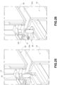
- the first sash 20 is mounted at the first upright 11 of the main frame 10. In the positions shown in Figure 1-3 , the sash 20 is locked in rotation by engagement with a locking pin 17, shown in Figure 25 and 26 .
- a locking pin 17, shown in Figure 25 and 26 Such locking pin 17 is mounted on a movable structure 18 arranged inside the lower cross-piece 13, and connecting the locking pin 17 to the rails 15 of the lower cross-piece 13. In this way, the locking pin is able to move integrally with the rails 15 of the lower cross-piece 13. Therefore, in the forward position of the rails 15, the locking pin 17 protrudes beyond the top wall 13a of the cross-piece 13, through an opening 13c formed in such wall ( Figure (25 ).
- the locking pin 17 engages a seat 23 arranged in the lower side of the first sash 20, preventing the first sash 20 from rotating about the axis Y thereof.
- the locking pin 17 is retracted so as not to interfere with the first sash 20 ( Figure 26 ), and therefore the first sash is free to rotate about the axis Y thereof.
- a locking pin identical to the one described above is arranged in the upper cross-piece 14, and connected in the same way with the rails 16 arranged in the upper cross-piece 14.
- the second sashes 30, 40 are displaceable by sliding between a first position far from the first upright 11 of the main frame 10 (shown in Figure 1 and 2 ) and a second position adjacent to said first upright 11 (shown in Figure 3 ). In the aforesaid second position, the second sashes 30, 40 are engageable with an abutment part 22 of the first sash 20. Such abutment part 22 protrudes orthogonally with respect to the plane defined by the first sash 20 and is integral with the first sash 20, in particular with the upright 21 thereof.
- At least one automatic coupling device 50 of a type known per se (in the example, at least one automatic coupling device for each sliding sash 30, 40) is also provided, comprising a first spring-loaded part 51 arranged on the abutment part 22 of the first sash 20 and a second part 52 arranged on each of the second sashes 30, 40.
- An engagement between the first spring-loaded part 51 and the second spring-loaded part 52 causes a stop (not shown) to snap into the first spring-loaded part 51, which holds the second spring-loaded part 52 against the first spring-loaded part 51.
- the fastening devices 50 are therefore configured to automatically fasten the second sashes 30, 40 to the abutment part 22 of the first sash 20 when the second sashes 30, 40 reach the second position thereof shown in Figure 3 .
- the automatic coupling device 50 described above further comprises a spring-loaded control member 53 arranged on the first spring-loaded part 51 and operable to cause the release of the second part 52 from the first spring-loaded part 51. Once operated and then released, such spring-loaded control member 53 elastically returns to the rest position thereof. The operation of the spring-loaded control member 53 will be described below.
- the first sash 20 forms with the second sashes 30, 40 coupled thereto a sash pack capable of rotating as a whole.
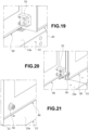
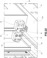
- Means are also provided to support the second sashes 30, 40 in the packed condition shown in Figure 3 and 4 , which in the illustrated example are shown in Figures 19-22 and Figures 23-24 .
- the means shown in Figures 19-22 comprise at least one female block 55 and at least one male engagement element 56 capable of engaging a slit formed in the female block 55 to achieve a prismatic coupling between adjacent sashes when the sashes are in the grouped condition ( Figure 22 ).
- the female blocks 55 and/or the male coupling elements 56 are arranged on the side of each sash 20, 30, 40 further away from the upright 11 of the main frame 10.
- Figure 19-22 show only those elements that are arranged at the lower side of the sashes 20-40; it is however understood that similar elements are also arranged at the upper side of the sashes 20-40.
- the arrangement and shape of the elements may be different from that shown in Figure 19-22 .
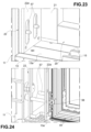
- the means shown in Figure 23, 24 comprise support pins 57 fastened to the abutment part 22 of the first sash 20, and capable of being inserted into respective seats 58 arranged on the uprights 31 and 41 of the second sashes 30, 40 when the sashes are in the grouped condition ( Figure 24).
- Figure 23-24 show only the elements arranged at the lower side of the sashes 20-40; it is understood, however, that similar elements are also arranged at the upper side of the sash 20-40.
- the arrangement and shape of the elements may be different from that shown in Figure 23-24 .
- the door 1 further comprises a control system 60 arranged in the main frame 10, in particular in the first upright 11, and operable to move the rails 15, 16 between the forward position thereof shown in Figure 5 and the retracted position thereof shown in Figure 6 .
- a control system 60 arranged in the main frame 10, in particular in the first upright 11, and operable to move the rails 15, 16 between the forward position thereof shown in Figure 5 and the retracted position thereof shown in Figure 6 .
- the control system 60 comprises a manually operable control element 61 mounted on the first upright 11, in particular a control element 61 rotatable about a horizontal axis X, such as a handle, shown in Figure 2-4 .
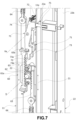
- the control system 60 further comprises control transmission means connecting the rails 15, 16 to the control element 61, an example of which is shown in Figure 7-11 .
- a first position (for example a lowered position) of the control element 61 corresponds to the forward position of the rails 15, 16, and a second position (for example a raised position) of the control element 61 corresponds to the retracted position of the rails 15, 16.
- control system 60 can be a system servo-assisted by an electric actuator, which is controlled by a manually operated push-button.
- control transmission can be constituted in part by components of the electric actuator, and in part by any further elements connecting the electric actuator to the rails 15, 16.
- the control transmission means comprise a gear wheel 62 which is coaxial and rotationally integral with a shaft 61a of the control element 61.
- the gear wheel 62 is coupled with two rack elements 63 extending vertically within the first upright 11 of the frame 10, wherein one thereof is connected in a force transmitting manner with the rails 15 of the lower cross-piece 13, and the other is connected in a force transmitting manner with the rails 16 of the upper cross-piece 14.
- the two rack elements 63 are coupled to respective rails in such a way as to be able to translate vertically, according to the direction indicated by the arrows Z1 and Z2.
- the rack elements 63 are coupled with diametrically opposite portions of the gear wheel 62, and therefore the two rack elements 63 are able to move in opposite directions relative to one another.
- the control transmission further comprises two return rods 64, which connect the rack elements 63 with the rails 15 of the lower cross-piece 13 and with the rails 16 of the upper cross-piece 14. It should be noted, for clarity, that in the example shown, the vertical movement of each rack element assembly 63/return rod 64 is inverted with respect to the movement of the respective rails 15, 16, with further transmission elements (such as gears), not shown in the figures, being arranged between each return rod 64 and the respective rails 15, 16.
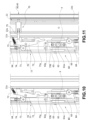
- the door 1 further comprises a first safety system arranged partly in the frame 10 and partly on the first sash 20.
- the first safety system 70 is switchable between two locking positions (shown in Figure 8 and 10 ), in which the first safety system 70 locks the control system 60 and the rails 15, 16 in the forward position and, respectively, in the retracted position, and an inactive position (shown in Figure 9 and 11 ), in which the first safety system 70 does not interfere with the control system 60.
- the first safety system 70 is configured to be switched from the first locking position ( Figure 8 ) to the inactive position ( Figure 9 ) by virtue of the second sashes 30, 40, when the second sashes 30, 40 reach the engagement position with the abutment part 22 of the first sash 20, shown in Figure 3 .
- the first safety system 70 is configured to be switched from the second locking position ( Figure 10 ) to the inactive position ( Figure 11 ) by virtue of the sash pack 20-40 insofar as such sash pack reaches the position aligned with the rails 15, 16 (i.e. the "closed" position shown in Figure 3 ).
- the first safety system 70 comprises a rocker arm 71 pivoted to the first upright 11 of the frame 10, and rotatable about a horizontal axis Xa orthogonal to the plane defined by the sashes 20-40. More precisely, there are two rocker arms 71 associated with the second sashes 30 and 40, respectively, and which may be rotated independently with respect to one another. In the case of a different number of second sashes, there would be a corresponding number of rocker arms.
- Each rocker arm 71 is elastically loaded by means of a respective spring-loaded 72 arranged between the rocker arm 71 and a part integral with the first upright 11 of the frame 10.
- Each rocker arm 71 has a first end 73 engageable with a relevant pin 63a integral with one of the rack elements 63.
- the pins 63a (wherein only one thereof is visible in the figures) are integral with the rack element 63 connected to the rails 16 associated with the upper cross-piece 14.
- at least one of the pins 63a interferes with the relevant first end 73 of the relevant rocker arm 71 thereby preventing the movement of the rack element 63 and thus the manual actuation of the command element 61.
- each rocker arm 71 is provided with a first engagement portion 73a and a second engagement portion 73b, which are configured to interfere with the relevant pin 63a in the first locking position ( Figure 8 ) and in the second locking position ( Figure 9 ), respectively.
- Each rocker arm 71 also has a second end 74 opposite the first end 73. Such second end 73 is engageable by a respective push rod 75 arranged upon the first sash 20 for causing the respective rocker arm 71 to rotate against the action of the respective spring-load 72.
- the push rods 75 are arranged inside the abutment part 22 of the first sash 20, and are movable along a horizontal direction Za parallel to the plane defined by the sashes 20-40.
- the push rods 75 may be elastically loaded by respective springs, towards said second sashes 30, 40.
- the push rods 75 each have a proximal end that protrudes towards the first upright 11 of the frame 10, through a respective opening formed in a wall 22a of the abutment part 22 of the first sash 20.
- the proximal ends of the push rods 75 are able to engage the respective rocker arms 71 through respective openings formed in a wall 11a of the first upright 11 of the frame 10.
- the push rods 75 each have a distal end protruding towards the second sashes 30, 40, through a respective opening formed in another wall 22b of the abutment part 22 of the first sash 20.
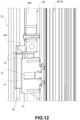
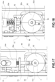
- the door 1 further comprises a release system 80, shown in Figure 12-18 , which is arranged partly in the frame 10 of the door 1, and partly on the first sash 20.
- the release system 80 is operable to act upon the automatic coupling devices 50, causing the release of the second sashes 30, 40 from the abutment part 22 of the first sash 20.
- the release system 80 comprises a manually operable control element 81 mounted on the first upright 11 of the main frame 10.
- the manually operable control element 81 is a slider displaceable along a vertical direction, defined by a groove 82 formed on a wall of the first upright 11.
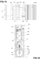
- the release system 80 comprises a first transmission part 83 arranged in the first upright 11 of the main frame 10 and connected to the control element 81.
- Such first transmission part is shown in particular in Figures 15 and 16 , and comprises a sliding plate 83a mounted inside the first upright 11 and movable along a vertical direction.
- the sliding plate 83a is integral with the control element 81; the connection point between the control element 81 and the sliding plate 83a is indicated with 83b.
- the sliding plate 83a is integral with a return rod 83c, which has an engagement tab 83d at one end protruding towards the first sash 20, through an opening formed in the wall 11a of the first upright 11.
- the sliding plate 83a is then coupled to a spring-load 83e, which pushes it towards the resting position thereof.
- the release system 80 further comprises a second transmission part 84 arranged in the abutment part 22 of the first sash 20.
- This second transmission part is shown in particular in Figure 12-15 and comprises a return rod 84a mounted to slide vertically inside the abutment part 22.
- An engagement tab 84b protruding towards the first upright 11 of the main frame 10 is fastened at one end of the return rod 84a, through an opening formed in the wall 22a of the abutment part 22 of the first sash 20 facing the first upright 11.
- the manual movement of the control element 81 (in particular the lowering thereof), against the action of the spring-loaded 83e, causes the engagement tab 83d of the first transmission part 83 to move, which thereby engages the engagement tab 84b of the second transmission part 84.
- the consequent movement of the return rod 84a of the second transmission part 84 causes such return rod to actuate the spring-loaded control members 53 of the two automatic coupling devices 50 respectively associated with the two second sashes 30, 40, causing the release of the second sashes 30, 40 from the first sash 20.
- the door 1 further comprises a second safety system 90 associated with the release system 80, shown in particular in Figure 16-18 .
- the second safety system 90 comprises a push rod 91 integral in translation with the sliding plate 91, and a safety disk 92 integral in rotation with the shaft 61a of the control element 61 of the control system 60 and arranged in front of the push rod 91.
- the safety disk 92 has an engagement seat 93 formed as a recess on a radially outer surface 92a thereof.
- the engagement seat 93 of the safety disk 92 is able to receive the push rod 91 insofar as it faces said push rod.
- the push rod 91 therefore has sufficient space to move by virtue of the fact that it may penetrate the engagement seat 93, allowing the entire release system 80 to move.
- the second safety system 90 is therefore switchable between a locking position ( Figure 18 ), wherein the second safety system 90 locks the release system 80, and an inactive position ( Figure 17 ), wherein the second safety system 90 does not interfere with the release system 80.
- the second safety system 90 is configured to be switched from the locked position thereof to the inactive position thereof (and vice versa) by the control element 61 of the control system 60.
- the control element 61 the handle
- the second safety system 90 is in the inactive position.
- the control element 61 is in the position shown in Figure 4 , therefore with the rails 15, 16 in the retracted position thereof or even with the entire pack formed by the sashes 20-40 in the rotated position
- the second safety system 90 is in the locked position, preventing the second sashes 30, 40 from being inadvertently released.
- the second sashes 30, 40 may slide along the rails 15, 16 until reaching the position shown in Figure 3 in which the second sashes 30, 40 engage with the abutment part 22 of the first sash 20, by virtue of the automatic coupling devices 50.
- Reaching the position shown in Figure 3 causes the first safety system 70 to switch from the first locking position thereof to the inactive position thereof, this by virtue of the engagement of the push rods 75 on the part of the second sashes 30, 40.
- the control system 60 is thus released from the first safety system 70, and the control element 61 of the control system may be rotated from the position shown in Figure 3 to the position shown in Figure 4 to cause the rails 15, 16 to retract.
- the second sashes 340, 40 are thus released from the rails, and therefore the inner pack formed by the first sash 20 with the second sashes 30, 40 coupled thereto may rotate as a normal hinged sash. It should be noted that in the position of Figure 1 and 2 , any undesired rotation of the first sash 20 is prevented by the coupling between the locking pin 17 of the lower cross-piece 13 and the lower side of the first sash 20, and by the coupling between the locking pin of the upper cross-piece 14 and the upper side of the first sash 20. The retraction of the rails 15, 16 also results in the retraction of the locking pins, which thus makes the first sash 20 free to rotate about the axis Y thereof.
- any undesired release of the second sashes 30, 40 is prevented by the fact that the second safety system 90 is in the locked position, by virtue of the specific position of the command element 61 (the handle) of the command system 60, thus preventing the operation of the release system 80.
- the control element 61 of the control system 60 may only be actuated when the sash pack 20-40 is returned to the position thereof aligned with the rails 15, 16. Otherwise, the push rods 75 arranged in the abutment part 22 of the second sash 20 would be far from the rocker arms 71 arranged within the first upright, and thus the first safety system 70 would be in the second locking position thereof which prevents the control element 61 of the control system 60 from being actuated. This prevents the rails 15, 16 from being inadvertently brought back to the forward position thereof before having moved the second sashes 30, 40 into the correct position thereof.
Landscapes
- Engineering & Computer Science (AREA)
- Civil Engineering (AREA)
- Structural Engineering (AREA)
- Mechanical Engineering (AREA)
- Wing Frames And Configurations (AREA)
- Hinges (AREA)
Applications Claiming Priority (1)
| Application Number | Priority Date | Filing Date | Title |
|---|---|---|---|
| IT202300023370 | 2023-11-07 |
Publications (2)
| Publication Number | Publication Date |
|---|---|
| EP4553264A1 true EP4553264A1 (fr) | 2025-05-14 |
| EP4553264B1 EP4553264B1 (fr) | 2026-04-22 |
Family
ID=89474304
Family Applications (1)
| Application Number | Title | Priority Date | Filing Date |
|---|---|---|---|
| EP24211162.3A Active EP4553264B1 (fr) | 2023-11-07 | 2024-11-06 | Porte comprenant au moins un battant coulissant et un battant articulé |
Country Status (4)
| Country | Link |
|---|---|
| US (1) | US20250146345A1 (fr) |
| EP (1) | EP4553264B1 (fr) |
| AU (1) | AU2024259776A1 (fr) |
| TW (1) | TW202532739A (fr) |
Citations (2)
| Publication number | Priority date | Publication date | Assignee | Title |
|---|---|---|---|---|
| KR100741813B1 (ko) * | 2006-05-18 | 2007-07-23 | 주식회사 고려풍국건축사사무소 | 건축물의 창문 회전구조 |
| US20180223573A1 (en) * | 2017-02-03 | 2018-08-09 | Assa Abloy Entrance Systems Ab | Automatically actuated door lock system |
Family Cites Families (23)
| Publication number | Priority date | Publication date | Assignee | Title |
|---|---|---|---|---|
| US2818614A (en) * | 1956-07-23 | 1958-01-07 | Jr Frank Lapka | Threshold |
| US3750334A (en) * | 1971-07-19 | 1973-08-07 | Republic Industries | Sliding swinging door suspension |
| DE2502765C2 (de) * | 1975-01-24 | 1983-04-14 | Seawell S.A., Luxembourg | Raumteiler in Form einer Trennwand |
| FI1694U1 (fi) * | 1994-08-17 | 1995-01-12 | Alusystems Ky | Svaengbar balkongglaskonstruktion |
| SG70091A1 (en) * | 1998-06-18 | 2000-01-25 | Lim Choo Siong | A door assembly |
| US6422287B1 (en) * | 2000-07-10 | 2002-07-23 | James Bradley Wilke | Slide/swing patio door |
| US20070069524A1 (en) * | 2005-09-14 | 2007-03-29 | Chen-Feng Lin | Locking mechanism of braking device for aluminum doors and windows |
| KR200410198Y1 (ko) * | 2005-12-09 | 2006-03-07 | 주식회사 알루스 | 회전가능한 슬라이딩도어 장치 |
| US7451802B2 (en) * | 2006-01-25 | 2008-11-18 | Nabco Entrances, Inc. | Slidable door assemblies with automatic pivot latching |
| KR100621644B1 (ko) * | 2006-05-18 | 2006-09-07 | 주식회사 티씨엠씨건축사사무소 | 건축물의 창문 개폐구조 |
| WO2009008749A1 (fr) * | 2007-07-12 | 2009-01-15 | Threshold Solutions Limited | Optimisations concernant des seuils de porte |
| KR20090006190U (ko) * | 2007-12-18 | 2009-06-23 | 한국건설기술연구원 | 미닫이 및 여닫이 겸용 도어 시스템 |
| US8096342B2 (en) * | 2009-09-28 | 2012-01-17 | Assa Abloy Ip Ab | Door package |
| US8806807B2 (en) * | 2009-10-26 | 2014-08-19 | Alan Rees | Sliding door structure having sliding doors and pivoting doors |
| US8756864B2 (en) * | 2010-09-17 | 2014-06-24 | Stanley Black & Decker, Inc. | Slide door |
| US9194172B2 (en) * | 2010-11-01 | 2015-11-24 | Alan Rees | Sliding door structure having sliding doors and pivoting doors |
| KR20150006589A (ko) * | 2013-07-09 | 2015-01-19 | 한승관 | 미닫이 창호용 창틀 구조체 |
| KR20150006588A (ko) * | 2013-07-09 | 2015-01-19 | 한승관 | 미닫이 창호용 창틀 구조체 |
| US9816311B2 (en) * | 2015-07-17 | 2017-11-14 | Eutimio Reyes | Portable barrier for a door sill |
| US10280678B1 (en) * | 2015-10-21 | 2019-05-07 | Landert Motoren Ag | Breakout sliding door system with pivoting rod |
| US20170204644A1 (en) * | 2016-01-18 | 2017-07-20 | Robert Mc Mullen, JR. | Combination Door Assembly |
| US11098514B2 (en) * | 2018-12-20 | 2021-08-24 | Pgt Innovations, Inc. | Sliding door system with mono-track assemblies |
| KR102563206B1 (ko) * | 2020-11-13 | 2023-08-04 | 김현민 | 창문구조 |
-
2024
- 2024-11-06 EP EP24211162.3A patent/EP4553264B1/fr active Active
- 2024-11-07 TW TW113142718A patent/TW202532739A/zh unknown
- 2024-11-07 AU AU2024259776A patent/AU2024259776A1/en active Pending
- 2024-11-07 US US18/939,619 patent/US20250146345A1/en active Pending
Patent Citations (2)
| Publication number | Priority date | Publication date | Assignee | Title |
|---|---|---|---|---|
| KR100741813B1 (ko) * | 2006-05-18 | 2007-07-23 | 주식회사 고려풍국건축사사무소 | 건축물의 창문 회전구조 |
| US20180223573A1 (en) * | 2017-02-03 | 2018-08-09 | Assa Abloy Entrance Systems Ab | Automatically actuated door lock system |
Also Published As
| Publication number | Publication date |
|---|---|
| US20250146345A1 (en) | 2025-05-08 |
| EP4553264B1 (fr) | 2026-04-22 |
| TW202532739A (zh) | 2025-08-16 |
| AU2024259776A1 (en) | 2025-05-22 |
Similar Documents
| Publication | Publication Date | Title |
|---|---|---|
| US5337210A (en) | Drawout type switch gear | |
| CN103827420B (zh) | 具有顺序驱动的锁定元件的多点锁 | |
| US5056877A (en) | Locking anti-tip device | |
| CA2985919C (fr) | Porte-charge comprenant un agencement de verrouillage | |
| MX2011006233A (es) | Cerradura para puerta de alta seguridad. | |
| AU2012322987A1 (en) | Highly safe control mechanism for a device for the sealed transfer between two closed spaces | |
| EP3876369B1 (fr) | Mécanisme d'interverrouillage mécanique | |
| EP4553264A1 (fr) | Porte comprenant au moins un battant coulissant et un battant articulé | |
| EP2165398B1 (fr) | Système d'arbre d'entraînement coaxial, sous-groupe frontal, tiroirs électroniques et armoire de commande | |
| US20030126896A1 (en) | Push-button lock device | |
| EP2886755B1 (fr) | Verrou à combinaison de bouton-poussoir | |
| JP7621490B2 (ja) | 引出形電気切替装置のためのシャシ装置およびそのような装置を備えるアセンブリ | |
| US12281498B2 (en) | Sliding door | |
| CN213005409U (zh) | 一种多刀架伸缩刀 | |
| US4884853A (en) | Drawer interlocking means for storage cabinet | |
| CN217239998U (zh) | 开关柜 | |
| US9493966B2 (en) | Gate lock | |
| CN217485320U (zh) | 用于自动转换开关的位置锁定装置和电气设备 | |
| BR102024023240A2 (pt) | Porta com pelo menos um caixilho deslizante e um caixilho articulado | |
| CN219873228U (zh) | 联锁机构及充气柜 | |
| CN220106304U (zh) | 用于开关柜的联锁系统和开关柜 | |
| CN218896568U (zh) | 一种用于开关装置的联锁机构及电气柜 | |
| RU2829835C1 (ru) | Дверной замок | |
| CN223402127U (zh) | 一种低压柜抽屉的手摇推进系统 | |
| CN111193215B (zh) | 开关柜的活门驱动机构、活门机构和手车联动机构 |
Legal Events
| Date | Code | Title | Description |
|---|---|---|---|
| PUAI | Public reference made under article 153(3) epc to a published international application that has entered the european phase |
Free format text: ORIGINAL CODE: 0009012 |
|
| STAA | Information on the status of an ep patent application or granted ep patent |
Free format text: STATUS: THE APPLICATION HAS BEEN PUBLISHED |
|
| AK | Designated contracting states |
Kind code of ref document: A1 Designated state(s): AL AT BE BG CH CY CZ DE DK EE ES FI FR GB GR HR HU IE IS IT LI LT LU LV MC ME MK MT NL NO PL PT RO RS SE SI SK SM TR |
|
| STAA | Information on the status of an ep patent application or granted ep patent |
Free format text: STATUS: REQUEST FOR EXAMINATION WAS MADE |
|
| 17P | Request for examination filed |
Effective date: 20251003 |
|
| GRAP | Despatch of communication of intention to grant a patent |
Free format text: ORIGINAL CODE: EPIDOSNIGR1 |
|
| STAA | Information on the status of an ep patent application or granted ep patent |
Free format text: STATUS: GRANT OF PATENT IS INTENDED |
|
| INTG | Intention to grant announced |
Effective date: 20251117 |
|
| GRAS | Grant fee paid |
Free format text: ORIGINAL CODE: EPIDOSNIGR3 |
|
| GRAA | (expected) grant |
Free format text: ORIGINAL CODE: 0009210 |
|
| STAA | Information on the status of an ep patent application or granted ep patent |
Free format text: STATUS: THE PATENT HAS BEEN GRANTED |
|
| AK | Designated contracting states |
Kind code of ref document: B1 Designated state(s): AL AT BE BG CH CY CZ DE DK EE ES FI FR GB GR HR HU IE IS IT LI LT LU LV MC ME MK MT NL NO PL PT RO RS SE SI SK SM TR |
|
| REG | Reference to a national code |
Ref country code: CH Ref legal event code: F10 Free format text: ST27 STATUS EVENT CODE: U-0-0-F10-F00 (AS PROVIDED BY THE NATIONAL OFFICE) Effective date: 20260422 |