EP4553322A1 - Turbomachine et procédé de fabrication - Google Patents
Turbomachine et procédé de fabrication Download PDFInfo
- Publication number
- EP4553322A1 EP4553322A1 EP23315411.1A EP23315411A EP4553322A1 EP 4553322 A1 EP4553322 A1 EP 4553322A1 EP 23315411 A EP23315411 A EP 23315411A EP 4553322 A1 EP4553322 A1 EP 4553322A1
- Authority
- EP
- European Patent Office
- Prior art keywords
- bearing
- impeller
- turbo machine
- connecting structures
- shaft
- Prior art date
- Legal status (The legal status is an assumption and is not a legal conclusion. Google has not performed a legal analysis and makes no representation as to the accuracy of the status listed.)
- Withdrawn
Links
Images

Classifications
-
- F—MECHANICAL ENGINEERING; LIGHTING; HEATING; WEAPONS; BLASTING
- F04—POSITIVE - DISPLACEMENT MACHINES FOR LIQUIDS; PUMPS FOR LIQUIDS OR ELASTIC FLUIDS
- F04D—NON-POSITIVE-DISPLACEMENT PUMPS
- F04D17/00—Radial-flow pumps, e.g. centrifugal pumps; Helico-centrifugal pumps
- F04D17/08—Centrifugal pumps
- F04D17/10—Centrifugal pumps for compressing or evacuating
-
- F—MECHANICAL ENGINEERING; LIGHTING; HEATING; WEAPONS; BLASTING
- F01—MACHINES OR ENGINES IN GENERAL; ENGINE PLANTS IN GENERAL; STEAM ENGINES
- F01D—NON-POSITIVE DISPLACEMENT MACHINES OR ENGINES, e.g. STEAM TURBINES
- F01D25/00—Component parts, details, or accessories, not provided for in, or of interest apart from, other groups
- F01D25/08—Cooling; Heating; Heat-insulation
- F01D25/14—Casings modified therefor
- F01D25/145—Thermally insulated casings
-
- F—MECHANICAL ENGINEERING; LIGHTING; HEATING; WEAPONS; BLASTING
- F04—POSITIVE - DISPLACEMENT MACHINES FOR LIQUIDS; PUMPS FOR LIQUIDS OR ELASTIC FLUIDS
- F04D—NON-POSITIVE-DISPLACEMENT PUMPS
- F04D29/00—Details, component parts, or accessories
- F04D29/05—Shafts or bearings, or assemblies thereof, specially adapted for elastic fluid pumps
- F04D29/056—Bearings
-
- F—MECHANICAL ENGINEERING; LIGHTING; HEATING; WEAPONS; BLASTING
- F04—POSITIVE - DISPLACEMENT MACHINES FOR LIQUIDS; PUMPS FOR LIQUIDS OR ELASTIC FLUIDS
- F04D—NON-POSITIVE-DISPLACEMENT PUMPS
- F04D29/00—Details, component parts, or accessories
- F04D29/40—Casings; Connections of working fluid
- F04D29/42—Casings; Connections of working fluid for radial or helico-centrifugal pumps
- F04D29/4206—Casings; Connections of working fluid for radial or helico-centrifugal pumps especially adapted for elastic fluid pumps
-
- F—MECHANICAL ENGINEERING; LIGHTING; HEATING; WEAPONS; BLASTING
- F04—POSITIVE - DISPLACEMENT MACHINES FOR LIQUIDS; PUMPS FOR LIQUIDS OR ELASTIC FLUIDS
- F04D—NON-POSITIVE-DISPLACEMENT PUMPS
- F04D29/00—Details, component parts, or accessories
- F04D29/58—Cooling; Heating; Diminishing heat transfer
- F04D29/582—Cooling; Heating; Diminishing heat transfer specially adapted for elastic fluid pumps
- F04D29/5853—Cooling; Heating; Diminishing heat transfer specially adapted for elastic fluid pumps heat insulation or conduction
-
- F—MECHANICAL ENGINEERING; LIGHTING; HEATING; WEAPONS; BLASTING
- F05—INDEXING SCHEMES RELATING TO ENGINES OR PUMPS IN VARIOUS SUBCLASSES OF CLASSES F01-F04
- F05D—INDEXING SCHEME FOR ASPECTS RELATING TO NON-POSITIVE-DISPLACEMENT MACHINES OR ENGINES, GAS-TURBINES OR JET-PROPULSION PLANTS
- F05D2240/00—Components
- F05D2240/10—Stators
- F05D2240/15—Heat shield
Definitions
- the present invention relates to turbo machine, e.g., a cryogenic turbo machine, with an impeller mounted on a shaft, and to a method of manufacturing such turbo machine.
- turbo machine e.g., a cryogenic turbo machine
- impeller mounted on a shaft
- Turbo machines can be used in different applications.
- cryogenic applications i.e. applications with process gases at cryogenic temperatures, e.g., plants for air separation or the like
- cryogenic turbo machines like turbo expanders and/or compressors are often used.
- Such turbo machines typically comprise an expander impeller and/or a compressor impeller, which are fixed on a shaft.
- Such turbo machines typically also comprise an inlet or inlet channel configured to guide operating fluid, e.g., gas (or a fluid) like the mentioned process gas, to such impeller, and an outlet or outlet channel configured to guide said operating fluid, e.g., after expansion, from that impeller, e.g., to the outside.
- operating fluid e.g., gas (or a fluid) like the mentioned process gas
- outlet or outlet channel configured to guide said operating fluid, e.g., after expansion, from that impeller, e.g., to the outside.
- the impeller of the turbo machine and a corresponding impeller-sided bearing part are subject to very cold temperatures
- the shaft, its bearing and a corresponding bearing carrier are typically subject to ambient or at least warmer temperatures; bearings, e.g. can even be warmer than ambient temperature. This can lead to massive heat input from the cold to the warm parts, depending on the specific temperatures. It is therefore an object of the present invention to provide an improved turbo machine.
- turbo machines in particular cryogenic turbo machines, like turbo compressors or turbo expanders with an impeller arranged or mounted on a shaft.
- Types of turbomachines are, for example, centrifugal turbo machines and radial turbo machines.
- Such a turbo machine comprises an impeller, a bearing, a shaft, an impeller-sided bearing part and a bearing carrier. Said impeller is arranged on said shaft and said impeller can, at least partly, be enclosed by said impeller-sided bearing part. Further, said shaft is supported by said bearing and said bearing is supported in and, at least-partly, enclosed by said bearing carrier.
- such a turbo machine typically comprises an inlet (or inlet channel) configured to guide operating fluid, e.g., from an inlet opening, to said impeller, and an outlet or outlet channel configured to guide operating fluid from said impeller, e.g., to an outlet opening.
- Cryogenic turbo machines are used with operating fluid like gases or process gases (or fluids or process fluids) at cryogenic temperatures, i.e., very low temperatures of, e.g., less than -100°C or even down to -230°C or -250°C at the expander outlet or at the compressor inlet. Depending on the kind of turbo machine, such gases are compressed and/or expanded. Turbo machines in other applications can also be used with operating fluids at higher temperatures.
- the impeller-sided bearing part (enclosing the expansion impeller) is connected to the bearing carrier and the cold power can be extracted through a compressor impeller or through a generator connected to or arranged on said shaft.
- a generator can, for example, also be connected via a gear box.
- the cold power could, e.g., also be extracted via a brake.
- the fluid is expanded from high-pressure level to low pressure level. This expansion produces a high difference of temperature between the inlet (high-pressure area) and the outlet (low-pressure area).
- Typical values for hydrogen gas as operating fluid are, for example, an inlet temperature of -230°C and an outlet temperature at - 245°C, leading to a very low temperature in the expander impeller-sided bearing part.
- turbo machine with one or more connecting structures, e.g., rods or other support structures, and wherein said impeller-sided bearing part and said bearing carrier are spatially spaced apart from each other and connected to each another by said one or more connecting structures.
- turbo machine is provided with one or more isolation areas between said impeller-sided bearing part and said bearing, which one or more isolation areas adjoin said one or more connecting structures; said one or more isolation areas can be free of solid material.
- the turbo machine further comprises an enclosure configured to hermetically enclosing said one or more connecting structures and form said one or more isolation areas.
- an enclosure configured to hermetically enclosing said one or more connecting structures and form said one or more isolation areas.
- Such enclosure can have, for example, two parts, formed as rings and enclosing the connecting structures from the inner and outer side.
- said one or more isolation areas are evacuated to a pressure less than ambient pressure, preferably, less than 100 mbar. This further reduces heat transfer due to low heat transfer coefficients of low pressure gas and due to no or almost no convection. Note that an evacuation of said one or more isolation areas, should be as good as possible. A pure vacuum, however, will typically not be achieved. Nevertheless, pressures of, e.g., below 10 mbar or below 1 mbar can be considered a vaccum. Further note that said one or more isolation areas can also be filled with particular gases of low heat transfer coefficients and of low pressure.
- the turbo machine comprises more of said connecting structures, and said more connecting structure are spaced apart from each other, e.g., equally, and arranged annularly around the shaft. I this way, a stiff and robust connection between the impeller-sided bearing part and the bearing carrier can be provided.
- said impeller-sided bearing part, said bearing carrier and said one or more connecting structures form parts of a component made of a single piece, e.g. by casting. In this way, potential parts with higher heat transfer coefficients like welding seams or the like can be prevented.
- said impeller-sided bearing part, said bearing carrier and said one or more connecting structures can be connected by welding or other means
- the bearing carrier can be equipped with oil bearings, roller bearings, gas bearings or magnetic bearings; depending on the type of bearing, the bearing carrier can be formed or configured correspondingly.
- This invention allows to reduce the heat intakes from the warm bearing carrier side to the cryogenic (expander) side.
- the impeller (expander) casing which often has a temperature close to -200°C is connected though reduced number of local connecting structures (brackets), to the bearing carrier which is, typically, at ambient temperature.
- the thermal conduction section is reduced and the heat transfer between the two parts is maintained at a low level.
- connection between the impeller-sided bearing part and the bearing carrier can be closed hermetically and a vacuum can be created inside this chamber to avoid any convection.
- an anti-radiation sheet can be provided in this chamber to further reduce heat transfer.
- This connection system between cryogenic side and warm side of the turbo machine allows to maintain the heat intakes at a low level in order to increase the efficiency of the expansion and to maintain a positive temperature at the -bearing level located on impeller (expander) side.
- cryogenic turbo or rotating machines like radial cryogenic expanders connected to an oil break or to a generator, turboexpanders, centrifugal compressors, axial turbines, operating at cryogenic temperature and where there is need to minimize the heat transfer from the bearing carrier to the impeller-sided bearing part (machine housing).
- the concept is, in particular, applicable for cryogenic gases like hydrogen but can also be used for other cryogenic gases like helium or other ones.
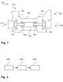
- Fig. 1 schematically illustrates a turbo machine 100 according to an embodiment of the invention.
- the turbo machine 100 e.g., a cryogenic turbo machine is, by means of example, configured as a compressor and an expander, i.e., both are combined in one turbo machine.
- Turbo machine 100 comprises, hence, two impellers, an impeller 110 and an impeller 120, both mounted on a shaft 130.
- the turbo machine 100 comprises channels 112 and 114 on the side of the impeller 110, the channels used respectively as inlet channel and outlet channel for the operating fluid to be compressed.
- the turbo machine 100 further comprises channels 122 and 124 on the side of the impeller 120, the channels used respectively as inlet channel and outlet channel for the operating fluid to be expanded.
- the impeller 110 is a compressor impeller and the impeller 120 is an expander impeller.
- the operating fluid to be compressed and the operating fluid to be expanded can have identical or can have different properties like pressure, temperature, chemical composition etc.
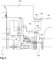
- Fig. 3 shows also parts of the turbomachine 100 in more detail and in a perspective view; in particular, the impeller-sided bearing part 150 and the bearing carrier 154 are shown.
- the rotation axis R is also shown for better understanding.
- an enclosure to hermetically enclose said one or more connecting structures and form said one or more isolation areas can be provided. This can comprise two parts of such an enclosure as shown in Fig. 2 , for example.
Landscapes
- Engineering & Computer Science (AREA)
- Mechanical Engineering (AREA)
- General Engineering & Computer Science (AREA)
- Physics & Mathematics (AREA)
- Thermal Sciences (AREA)
- Structures Of Non-Positive Displacement Pumps (AREA)
Priority Applications (2)
| Application Number | Priority Date | Filing Date | Title |
|---|---|---|---|
| EP23315411.1A EP4553322A1 (fr) | 2023-11-07 | 2023-11-07 | Turbomachine et procédé de fabrication |
| PCT/EP2024/081183 WO2025098993A1 (fr) | 2023-11-07 | 2024-11-05 | Turbomachine et procédé de fabrication |
Applications Claiming Priority (1)
| Application Number | Priority Date | Filing Date | Title |
|---|---|---|---|
| EP23315411.1A EP4553322A1 (fr) | 2023-11-07 | 2023-11-07 | Turbomachine et procédé de fabrication |
Publications (1)
| Publication Number | Publication Date |
|---|---|
| EP4553322A1 true EP4553322A1 (fr) | 2025-05-14 |
Family
ID=88923780
Family Applications (1)
| Application Number | Title | Priority Date | Filing Date |
|---|---|---|---|
| EP23315411.1A Withdrawn EP4553322A1 (fr) | 2023-11-07 | 2023-11-07 | Turbomachine et procédé de fabrication |
Country Status (2)
| Country | Link |
|---|---|
| EP (1) | EP4553322A1 (fr) |
| WO (1) | WO2025098993A1 (fr) |
Citations (3)
| Publication number | Priority date | Publication date | Assignee | Title |
|---|---|---|---|---|
| US10527062B2 (en) * | 2015-11-13 | 2020-01-07 | Mitsubishi Heavy Industries Compressor Corporation | Centrifugal compressor |
| EP3252284B1 (fr) * | 2016-06-01 | 2021-04-07 | BMTS Technology GmbH & Co. KG | Moteur à combustion interne comprenant deux turbocompresseurs |
| US11022125B2 (en) * | 2017-02-28 | 2021-06-01 | Mitsubishi Heavy Industries Compressor Corporation | Centrifugal compressor |
Family Cites Families (1)
| Publication number | Priority date | Publication date | Assignee | Title |
|---|---|---|---|---|
| CN201110280Y (zh) * | 2006-11-28 | 2008-09-03 | 上海通用泵机设备有限公司第一水泵厂 | 带加热机构的离心式煤浆泵 |
-
2023
- 2023-11-07 EP EP23315411.1A patent/EP4553322A1/fr not_active Withdrawn
-
2024
- 2024-11-05 WO PCT/EP2024/081183 patent/WO2025098993A1/fr active Pending
Patent Citations (3)
| Publication number | Priority date | Publication date | Assignee | Title |
|---|---|---|---|---|
| US10527062B2 (en) * | 2015-11-13 | 2020-01-07 | Mitsubishi Heavy Industries Compressor Corporation | Centrifugal compressor |
| EP3252284B1 (fr) * | 2016-06-01 | 2021-04-07 | BMTS Technology GmbH & Co. KG | Moteur à combustion interne comprenant deux turbocompresseurs |
| US11022125B2 (en) * | 2017-02-28 | 2021-06-01 | Mitsubishi Heavy Industries Compressor Corporation | Centrifugal compressor |
Also Published As
| Publication number | Publication date |
|---|---|
| WO2025098993A1 (fr) | 2025-05-15 |
Similar Documents
| Publication | Publication Date | Title |
|---|---|---|
| US2445661A (en) | Axial flow turbine, compressor and the like | |
| CN110023628B (zh) | 涡轮压缩机以及操作涡轮压缩机的方法 | |
| JP7819948B2 (ja) | 冷却機のターボ圧縮機アセンブリ | |
| KR20220156619A (ko) | 오버행된 터보기계를 갖는 일체형 밀폐 밀봉된 터보팽창기-발생기 | |
| JP2013513064A (ja) | 圧縮機端部ヘッド加熱装置 | |
| KR102733421B1 (ko) | 다단 터보기계 | |
| US9577494B2 (en) | Elastic cone for sealing and method | |
| EP4553322A1 (fr) | Turbomachine et procédé de fabrication | |
| US10808725B2 (en) | Turbomachine and method of operating a turbomachine | |
| EP2422050A1 (fr) | Amélioration d'une turbine pour l'expansion de gaz/vapeur | |
| CN112041543B (zh) | 蒸汽涡轮设备及联合循环设备 | |
| EP4545767A1 (fr) | Procédé de fonctionnement d'une turbomachine, turbomachine et procédé de fabrication | |
| AU2023275836B2 (en) | Integral expander generator for hydrogen applications with magnetic bearings | |
| CN121941835A (zh) | 用于操作涡轮机的方法、涡轮机和制造方法 | |
| Gistau et al. | Application range of cryogenic centrifugal compressors | |
| US20050120719A1 (en) | Internally insulated turbine assembly | |
| US20250059982A1 (en) | Turbo machine and method of manufacturing | |
| RU2842225C1 (ru) | Турбодетандерный агрегат | |
| RU2027957C1 (ru) | Турбодетандер высокого давления | |
| US3202341A (en) | Turbomachines assembly | |
| US12169081B2 (en) | Integrated expander and motor-compressor assembly and closed loop cooling circuit comprising such an assembly | |
| US5628194A (en) | Process for pumping gaseous helium at cryogenic temperatures by a positive displacement pump |
Legal Events
| Date | Code | Title | Description |
|---|---|---|---|
| PUAI | Public reference made under article 153(3) epc to a published international application that has entered the european phase |
Free format text: ORIGINAL CODE: 0009012 |
|
| STAA | Information on the status of an ep patent application or granted ep patent |
Free format text: STATUS: THE APPLICATION HAS BEEN PUBLISHED |
|
| AK | Designated contracting states |
Kind code of ref document: A1 Designated state(s): AL AT BE BG CH CY CZ DE DK EE ES FI FR GB GR HR HU IE IS IT LI LT LU LV MC ME MK MT NL NO PL PT RO RS SE SI SK SM TR |
|
| STAA | Information on the status of an ep patent application or granted ep patent |
Free format text: STATUS: THE APPLICATION IS DEEMED TO BE WITHDRAWN |
|
| 18D | Application deemed to be withdrawn |
Effective date: 20251115 |