EP4553339A2 - Fortschrittliche komponentenbasierte förderbandspleissvorrichtung - Google Patents
Fortschrittliche komponentenbasierte förderbandspleissvorrichtung Download PDFInfo
- Publication number
- EP4553339A2 EP4553339A2 EP24215951.5A EP24215951A EP4553339A2 EP 4553339 A2 EP4553339 A2 EP 4553339A2 EP 24215951 A EP24215951 A EP 24215951A EP 4553339 A2 EP4553339 A2 EP 4553339A2
- Authority
- EP
- European Patent Office
- Prior art keywords
- belt
- tension
- splicer
- link
- splice
- Prior art date
- Legal status (The legal status is an assumption and is not a legal conclusion. Google has not performed a legal analysis and makes no representation as to the accuracy of the status listed.)
- Pending
Links
Images







Classifications
-
- F—MECHANICAL ENGINEERING; LIGHTING; HEATING; WEAPONS; BLASTING
- F16—ENGINEERING ELEMENTS AND UNITS; GENERAL MEASURES FOR PRODUCING AND MAINTAINING EFFECTIVE FUNCTIONING OF MACHINES OR INSTALLATIONS; THERMAL INSULATION IN GENERAL
- F16G—BELTS, CABLES, OR ROPES, PREDOMINANTLY USED FOR DRIVING PURPOSES; CHAINS; FITTINGS PREDOMINANTLY USED THEREFOR
- F16G3/00—Belt fastenings, e.g. for conveyor belts
- F16G3/10—Joining belts by sewing, sticking, vulcanising, or the like; Constructional adaptations of the belt ends for this purpose
-
- F—MECHANICAL ENGINEERING; LIGHTING; HEATING; WEAPONS; BLASTING
- F16—ENGINEERING ELEMENTS AND UNITS; GENERAL MEASURES FOR PRODUCING AND MAINTAINING EFFECTIVE FUNCTIONING OF MACHINES OR INSTALLATIONS; THERMAL INSULATION IN GENERAL
- F16G—BELTS, CABLES, OR ROPES, PREDOMINANTLY USED FOR DRIVING PURPOSES; CHAINS; FITTINGS PREDOMINANTLY USED THEREFOR
- F16G3/00—Belt fastenings, e.g. for conveyor belts
- F16G3/003—Apparatus or tools for joining belts
-
- F—MECHANICAL ENGINEERING; LIGHTING; HEATING; WEAPONS; BLASTING
- F16—ENGINEERING ELEMENTS AND UNITS; GENERAL MEASURES FOR PRODUCING AND MAINTAINING EFFECTIVE FUNCTIONING OF MACHINES OR INSTALLATIONS; THERMAL INSULATION IN GENERAL
- F16G—BELTS, CABLES, OR ROPES, PREDOMINANTLY USED FOR DRIVING PURPOSES; CHAINS; FITTINGS PREDOMINANTLY USED THEREFOR
- F16G3/00—Belt fastenings, e.g. for conveyor belts
- F16G3/16—Devices or machines for connecting driving-belts or the like
-
- B—PERFORMING OPERATIONS; TRANSPORTING
- B65—CONVEYING; PACKING; STORING; HANDLING THIN OR FILAMENTARY MATERIAL
- B65G—TRANSPORT OR STORAGE DEVICES, e.g. CONVEYORS FOR LOADING OR TIPPING, SHOP CONVEYOR SYSTEMS OR PNEUMATIC TUBE CONVEYORS
- B65G15/00—Conveyors having endless load-conveying surfaces, i.e. belts and like continuous members, to which tractive effort is transmitted by means other than endless driving elements of similar configuration
- B65G15/30—Belts or like endless load-carriers
Definitions
- the present invention relates to repair of failed conveyor belts by compressive binding of a length of splice material into the failed belt with the application of process heating.
- the mentioned prior art D2 refers to a transportable device for vulcanizing founders.
- the invention relates to a device with the aid of endless connections of transport belts (Foerderbaenden) be prepared for vulcanization.
- the aim of the invention is to reduce the assembly and transport times, to allow the use of poorly accessible tape systems as much as possible, as well to increase the quality of vulcanizing.
- the aim is achieved by transportable vulcanization device which can be mounted in a few steps at the side and a high and permanent pressure achieved by a force generating device in conjunction with a system for a power transportation and for pressure increasing.
- the vulcanizing device consists of a compact press upper and lower press part, which are pressed against each other by means of hydraulic cylinders, deflection levers and toggle lever system.
- the mentioned prior art D4 refers to a tension link for a belt splicer.
- the invention relates to a tension link to a belt-splicer that is based on a rope loop of high strength synthetic fibre, wound around bosses, where the bosses and the loop are encapsulated in module plastic.
- the link connects cross-beams of the splicer. Additional features of the link include couplings which permit rotation when the beams deflect in bending.
- the links can be stored inside the hollow interior of the beams.
- the couplings include eccentrically mounted blocks that can be oriented to adjust the length of the link.
- the invention relates to minimazing the cool-down time by the use of a cooler having integral fins of high surface area, and the use of high efficiency fans.
- the heat-up time is minimized by the low mass of the cooler, and the prevention of transmission of heat to the housing.
- Recent technology involves the use of a pair of heat conductive platens which are placed over and under the belt splicing so as to at least completely cover the splice area being the length of the splice times the width of the belt.
- Upper and lower heating pads are positioned over the splice area.
- Such heating pads are known to include electrical resistance wire embedded in a pad of heat conductive silicone so as to provide the necessary heat and transmit the compressive stresses vertically through the splice.
- Above and below the heating pads are cooling platens used in sequence with the heating so as to cure the belt splice in the most optimal conditions. Control of the heating, cooling and pressure characteristics of the splice are critical as the belt will be put back into heavy industrial service almost immediately after the splice is concluded.
- the temperature of heating must be uniformly +/- 3 degrees C across the whole splice, preferably 0 degrees C under uniform and constant pressure. Cooling must be carefully controlled and uniform across the splice as well.
- Such belt splicers are effective for purpose but require custom engineering, especially for larger sizes, are costly to manufacture and maintain in stock and difficult to deliver intact when just in time tool availability is required. Many industrial locations would of necessity maintain a splicer in tool inventory in the event of a belt failure as a single conveyor belt failure can bring a production facility to an abrupt and catastrophic halt without notice. Given that these belts are critical components of heavy industry belt failure itself can spread damage across a facility and cause personnel injury.
- heating components have been based upon a heating wire strand uniformly and fully embedded in a heat transmissive silicone pad where the pad transfers the process pressure load around the heating wire to the process area.
- this wire heating was applied wherever space permitted often to the sacrifice of heating uniformity and speed.
- This aspect of the invention lies in the field of splicers for splicing conveyor-belts.
- the invention is concerned with the provision for adjustability of the splicer, to accommodate e.g. different belt-thicknesses.
- the belt-splicer 20 ( Fig. 1 ) includes above-and below-crossbeams 21A, 2IB.
- the crossbeams 21 span across the full width of the conveyor-belt 23 to be spliced.
- the belt being spliced comprises two belt-ends 23A, 23B, which are to be adhered together.
- the belt users prefer that the finished spliced-zone of the belt be of the same thickness as the parent belt.
- the two belt-ends 23A, 23B typically are interfaced conventionally in e.g. a tapered or chamfered overlapping configuration, or e.g. in a zig-zag pattern, being generally so configured as to create a large area of interface contact between the two belt-ends.
- splicing involves applying liquid rubber gum to the contact areas of the belt-ends, and subjecting the splice-zone to heat and pressure.
- the rubber undergoes vulcanization.
- the vulcanization having been done properly, the splice is (almost) as strong as the parent belt.
- Fig. 1 of the components that lie between the crossbeam, only the belt itself is shown.
- Fig. 2 shows the rest of the between-beams components, in detail, along with the two overlapping ends 23A, 23B of the belt 23.
- the portion 23A belongs to the end of the belt that extends into the plane of Fig. 2
- the portion 23B belongs to the end of the belt that extends out of Fig. 2 .
- the between-beams components in Fig. 2 include an inflation-bag 25.
- the inflation-bag may be located above or below the belt 23, depending on whether is it easier to accommodate the deflection movements upwards or downwards in the particular case.
- above-heater-platen 27A and a below-heater-platen 27B are also included between the crossbeams.
- above-and below-heat-insulation-layers 29A, 29B are also included between the crossbeams.
- the present belt-splicer 20 also includes provision for forced cooling of the splice interface, after the period of heating. Rapid forced cooling is preferred, when rapidity might be instrumental in procuring a more favourable molecular structure in the vulcanized rubber, compared with slow ambient cooling.
- the crossbeams 21 are long enough to protrude beyond the left and right side edges of the belt 23.
- the above-beam 21A is provided with a protruding above-left-end-boss 30AL, while the below-beam 21B is provided with a protruding below-left-end-boss 3OBL.
- the splicer 20 includes two tension-links, being a left tension-link 32L and a right tension-link 32R.
- the left tension-link 32L comprises an above-link-element 34AL and a below-link-element 34BL.
- Pivot-pins 36AL, 36BL secure the above-and below-left-link-elements 34AL, 34BL respectively to the above-and below-end-bosses 30AL, 30BL.
- below-link-element 34BL is plain, and is secured to the above-link-element 34AL by a lefi-clevis-pin 38L.
- the clevis-pin 38L passes through an above-clevis-hole 40AL in the above-link-element 34AL, and through a below-clevis-hole 40BL in the below-link-element 34BL.
- the inflation-bag 25 When the inflation-bag 25 is inflated (with a gas (e.g. air) or a liquid (e.g. water) under pressure) the resulting pressure is applied to the splice-zone of the two ends of the belt.
- the pressure is reacted by the above-and below-crossbeams 21A, 21B, and in turn by the two tension-links 32L, 32R.
- the pressure urges the crossbeams 21 to move apart in the up/down direction, and the tension-links 32 prevent that from happening.
- the inflation-bag 25 applies pressure over an area of, say, 0.25 sq. metres (400 sq. ins).
- the inflation pressure is typically ten atmospheres (15Opsi), so that the force reacted by the left and right tension-links 32L, 34R is typically thirty tonnes, i.e. fifteen tonnes in each tension-link.
- the designers must see to it that the tension-links 32 are capable of sustaining the imposed forces, with a suitable safety margin. But not only that: the tension-links 32 have to be assembled and disassembled with each splicing event, and the designers have to ensure that the tension-links 32 can only be assembled safely and properly. Also, over a long service period, the components of the tension-links can become less able to perform their functions. Also, inexperienced operators can make dangerous mistakes; and even the experienced operators can start to become careless as the operations become familiar and routine. It is up to the designers to see to it that these possibilities do not put the operators (and others) in danger.
- the degree to which the inflation-bag 25 is inflated during operation should be kept to a minimum. Too large an inflation, and portions of the material of the bag can start to bulge, perhaps leading to failure. Thus it is desirable, once the belt-splicer 20 has been assembled onto and around the two ends of the belt 23, and made ready for the splicing operation to commence, that the tension-links 32 hould be made as short as possible, thereby minimizing the degree to which the bag 25 is called upon to inflate and expand.
- the lengths of the left and right tension-links 32L, R should be adjustable as to their (vertical) lengths.
- the common reason why the length of the tension-links 32 needs to be adjustable is to cater for different thicknesses of the belts being spliced. To that extent, the required length of the tension-links can be predicted ahead of time. However, it is preferred that the manner of adjustment should be such that the tension-links can be fiNally adjusted by the operators, at the time of final assembly of the belt-splicer onto the belt.
- the clevis-holes 40AL, 40BL in the 1ink-elements 34 are of (vertically) elongated profile, and the clevis-pin 38L is of a complementary profile.
- the profile comprises two semi-circles joined by two straights.
- clevis-pins 38 are provided (i.e. a kit of clevis-pins is provided), which differ from each other as to the lengths of their profile-straights.
- the operators select which one of the several clevis-pins, in the kit, to use for the particular splicing event, on the basis of which of the several clevis-pins will minimize the degree of inflation of the bag 25 (while enabling the splicer to be assembled).
- the adjustability of the length of the tension-link derives from the fact that the larger the clevis-pin (i.e. the longer its profile straights), the smaller the overall length of the tension-links 32.
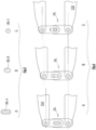
- Figs. 4, 5 show four sizes of clevis-pin 38.
- the clevis-pin 38L-A shown in Figs. 4A, 5A has the same profile as the clevis-holes 40 in the link-elements 34. (Or rather, of course, the clevis-pin is a little smaller than the holes, to enable assembly of the clevis-pin into and through the clevis-holes).
- the clevis-pin 38L-A is selected when the event requires the tension-link to be as short as possible.
- the clevis-pin 38L-A fills both the above-clevis-hole 40AL and the below-clevis-hole 40BL, preventing the link-elements 34L from moving apart.
- the clevis-pin 38L-C shown in Figs. 4C, 5C is actually circular (i.e. its profile-straights are of zero length). As shown in Figs.4C, the clevis-pin 38L-C is selected when it is required to make the tension-link as long as possible. The clevis-pin 38L-C enables or allows the link-elements to move apart the greatest distance.
- the components of the belt-splicer 20 are transported to the place where the splice is to be carried out. At this time, the two crossbeams 21A, 21B are separated from each other.
- the above-left-link-element 34AL and the above-right-link-element are never detached from the above-crossbeam 21A (except for service, etc.) and the below-left-link-element 34BL and the below-right-link-element are never detached from the below-crossbeam 21B during transport.
- the clevis-pins 38 are not assembled to the respective link-elements.
- clevis-pins 38 Provision is made, at the ends of the clevis-pins 38, for ensuring that the clevis pins, having been fully and properly assembled into the clevis- holes in the link elements, remain retained within the clevis-holes, and cannot inadvertently become mis-positioned, for any reason, until deliberately moved by the operators.
- the clevis-pin can be provided with though-holes for attachment of pull-rings, spring-clips, retainers, or the like.
- tension-link has been indicated as including an above-link-element and a below-link-element.
- the above-link- element 34AL as may be seen from Fig. 5 , comprises two above-link element structures 41A, side-by side.
- the below-link-element 34BL likewise, comprises two below-link-element-structures 41B, side-by side.
- the “tension-link” is the aggregate of however many such link-element-structures are present (and the number can be one, two, or more than two, as required.)
- the below-link element 34BL comprising the two below-link-element-structures
- a handle 43B serves to join the two below-link- element-structures, and to keep them in their side-by side relationship.
- the handle 43B also serves to help the operator manipulate the link-elements when assembling and removing the clevis-pin.
- the above-link-element 34AL is also provided with a handle, but this is not shown in Fig. 3 .
- the extent of the (vertical) adjustable-range of length of the tension-link 32 is determined by the (vertical) slot-lengths of the clevis-holes 40, and the (vertical) length of the profile of the clevis-pins 38.
- the need for adjustment is based mainly on the differences in nominal thickness of the various belts being spliced.
- other variables might be present, which contribute to the need for the tension-links to be of adjustable length - and conveyor - belts do vary from their nominal thickness.
- the designers should provide a range of adjustment of two or three cm - or more, of course, if the requirement (and the room) exists.
- the clevis-pin is subjected to shear-stress, under load, and the designers must see to it that even the smallest clevis-pins in the kit are able to support the maximum stress with a suitable safety margin. (It is not necessary that the smallest clevis-pins in the kit should have zero-length profile-straights.)
- the (vertical) length of the present tension-links is small, when compared with tension-links in other designs of belt splicer.
- typically the crossbeams are, by comparison, significantly taller, vertically, at their ends, than the present crossbeams. The taller the crossbeams, the longer the tension-links can be, and a longer tension-link can include the kind of length-adjustment facility that is based on a screw-thread.
- Screw-thread adjusters can be convenient in those cases (although screw - thread adjusters can have their own problems).
- the splicer includes provision for forced cooling.
- the forced cooling is done by means of e.g. water pipes embedded in the heater platens 27.
- the pipes are disposed side-by-side with the (electrical) heating cables required for the heating function, within the heater-platen.
- the present heater-platen should rather be regarded as a combined heating-and-cooling-platen.
- the combined-platen occupies hardly more than the vertical space that would be required anyway for a platen that contained just the heating elements.
- the cooling function has been provided in a separate cooling platen structure. This may be regarded as disadvantageous because the stack of the two platens inevitably occupies considerably more vertical space than one single combined heating-and-cooling platen. But also, when the heating platens are next to the belt, the cooling platens have to exert their thermal effects through the heating platens - which is significantly inefficient.
- the height of the stack of belt-splicer-components that lie between the crossbeams is significantly reduced when the separate heating-platen and cooling-platen are replaced by a combined heating- and-cooling platen.
- the present as-described manner of arranging tension-link length - adjustability being particularly suitable for use with crossbeams of low vertical height, is likewise also particularly suitable for use when the stack of components between the crossbeams is of low vertical height.
- the pivot-pins 36 enable the tension-links to pivot, under load, relative to the crossbeams.
- the lengths of the crossbeams are dictated by the width of the belt, which can be a considerable span.
- the crossbeams can undergo considerable deflection when under a load of several tonnes, and in fact the crossbeams can so deflect as to be several millimetres further apart in the middle of the span than at the edges of the belt.
- Such deflection gives rise to a significant rotational movement of the ends of the crossbeams relative to the tension-links (the tension-links themselves remain vertical during operation), and such rotation is accommodated by the pivot-pins 36.
- the left -clevis-pin 38L is long enough to extend right through both (or all) the link-element-structures, as in the as-depicted design.
- shorter clevis-pins could be used, which each extend through e.g. just one of the link-element-structures.
- the operators must take care to ensure that all the clevis-pins in the splicer are the same size.
- the clevis-pins 38 and the clevis-holes 40 are running-track-shaped i.e. have the shape of two semi-circles separated by two straights. Other shapes can be used - e.g. rectangular (preferably with rounded corners). The important aspects are that the components containing the shapes should be strong enough to accommodate the imposed stresses, should be inexpensive to manufacture, and should not pose problems of inconvenience during operational assembly and dis-assembly.
- This invention lies in the filed of splicers for splicing conveyor belts.
- the invention is concerned with edge-irons, which are used for constraining the side-edges of the belt-ends during splicing, and with the manner of supporting the same, within the splicer.
- the belt-splicer 20 includes above - and below-crossbeams 21A, 21B.
- the crossbeams 21 span across the full width of the conveyor-belt 23 to be spliced.
- the belt being spliced comprises two belt-ends 23 A, 23B, which are to be adhered together.
- Each edge-iron has a middle-facing-surface 50L, 50R ("middle” means the surface faces towards the middle of the belt) and an outward-facing-surface 51L, 51R.
- the edge-irons 49L, 49R are supplemented by left and right filler-strips 52L, 52R, each of which has a middle-facing-surface 53L, R and an outward-facing-surface 54L, R.
- the belt-ends 23A, 23B are compressed between an above-heater-platen 27A and a below-heater-platen 27B, (in fact, the heater-platens, in the depicted design are combined heating-and-cooling-platens, but are referred to, here, as heater-platens.)
- the compression forces on the belt, during splicing, are transmitted through the heater-platens.
- An upward-facing-surface 58 of the below-heater-platen 27B is in close contact with the underside of the belt 23, and a downward-facing-surface 59 of the above-heater-platen 27A is in close contact with the overside of the belt 23.
- a below-groove or slot 61L has been provided, which extends downwards into the material of the below-heater-platen 27B, down from the upward-facing-surface 58.
- the outer wall of the groove 61L is formed as a middle-facing-abutment-surface 63L.
- the outwards-facing-surface 51L of the left-edge-iron 49L abuts against the middle-facing-abutment-surface 63L of the left-below-groove 61L.
- the outward-facing-surface 51R of the right-edge-iron 49R abuts against the middle-facing-abutment-surface 63R of the right-below-groove 61R.
- the left filler-strip 52L fits between the left side-edge 56L of the belt 23 and the middle-facing-surface 50L of the left edge-iron 49L.
- the present filler-strips 52 are made of rubber, and are somewhat compressible.
- the material of the filler-strips should be selected on the basis of being compressible, in the sense of being able to conform to (and thereby to make a seal against) the (possibly-uneven) side edges of the two ends 23A, 23B of the belt to be spliced.
- conveyor belts are not noted for their freedom from variations in the width of the belt, not only after a period of service, but as-manufactured.
- the left and right filler-strips 52L, R are chosen as to their thicknesses on the basis of squeezing (compressing) the width of the belt tightly between the filler-strips 52.
- the left and right filler-strips 52L, R abut against the left and right edge-irons 49L, R and the edge-irons in turn abut against the middle-facing-abutment-surfaces 63L, R of the lefi and right grooves 61L, R.
- the squeeze force exerted on the width of the belt is reacted directly within the material of the below-heater-platen 27B.
- the two belt-ends 29A, B are laid upon the upward-facing-surface 58 of the below-heater-platen 27B ( Fig. 8 ).
- the left and right grooves 61L, 61R lie just outside the side edges 56 of the belt 23 and the edge-irons 49 and the filler strips 52 are assembled into their places.
- edge-irons 49 reside in the grooves 61 formed in the material of the below-heater-platen, nothing else is required, in order to react the lateral-squeeze-force that is applied to the side-edges 56 of the belt.
- This may be contrasted with prior art configurations of edge-irons, where, typically, further components are required in order to transmit the lateral squeeze force to some other part of the structure of the belt-splicer.
- the present design enables the lateral-squeeze force to be self-contained within the below-heater-platen 27B.
- a corresponding above-groove 65L has been formed upwards into the downward-facing-undersurface 59 of the above-heater-platen 27A.
- the outward-facing surface 51 of the edge-iron 49 again abuts against the middle- facing-abutment-surface 67 of the above-groove 65.
- Fig. 10 shows a variant, in which the downward-facing undersurface 59 of the above-heater-platen 27A is plain, i.e. has no groove. Now, the lateral-squeeze-force on the side-edges 56 of the width of the belt is reacted only within the below-heater-platen 27B.
- the crossbeams 21 are prevented from separating, when the belt 23 is under compression, by the tension-links 32.
- the tension-links 32 do not prevent the above-crossbeam 21A from being able to move laterally, relative to the below-crossbeam 21B, and (small) lateral movements can take place.
- edge-irons 49 engage their grooves 61, 65 in both the below-heater-platen 27B and the above-heater-platen 27A, such double-engagement constrains the below-heater-platen 27B and the above-heater-platen 27A against lateral movement relative to each other, and does so very securely.
- FIG. 11A shows the above-heater-platen 27A about to be lowered onto the belt 23.
- the structure that is in contact with the underside of the belt is the below-heater-platen.
- the function of the platen may be other than that of heater, or may include other functions besides that of heater (again, the present heater-platens also include facility for power cooling).
- the below-heater-platen may be referred to generally, as the below-belt -contacting-platen, or simply as the below-platen, rather than the below-heater-platen.
- the below-belt-contacting-platen should be provided with left and right middle-facing abutment-surfaces, and that the left and right edge-irons can engage those surfaces in order to react the lateral belt-squeeze forces.
- the following also should be mentioned. It is considerably more convenient to react the belt-squeeze forces within the below-platen, given that the edge-irons and associated components have to be assembled and configured on site, i.e. at the belt. It is more convenient to place the edge-irons and components on the oversurface of the below-platen, than it would be to do the same thing upwards to the undersurface of the above-platen. However, apart from that difference in convenience, the edge-irons and components can, if the designers so wish, provide the contained-within-the-platen reaction to the belt-squeeze forces in the above platen.
- the material of the upwards-facing surface of the below-belt-contacting-platen does not itself make direct touching contact with the belt.
- a (thin) sheet of release material is interposed between the platen and the belt, to act as an aid to separating the block from the belt, after heat treatment.
- the belt-contacting -platen may be defined as follows.
- the belt-contacting-platen is the nearest block of metal to the belt (above and below) that is at least 3mm thick overall (vertically).
- the thin sheet of release material is not itself the belt-contacting-platen.
- the middle-facing-abutment-surface 63 of the groove 61 is integral with the material of the below-platen.
- the middle-facing-abutment-surface 63 is defined as being integral with the platen when the middle-facing-abutment-surface is either formed monolithically with the platen, from one common piece of material (metal), or if formed separately, are fixed together so firmly and rigidly as to be functionally and operationally equivalent to having been formed from one common piece of material.
- the platen can be manufactured as, for example, an aluminium extrusion for the main length, and then aluminium end-caps, e.g. machined from solid, are affixed to the ends of the extrusion.
- the middle-facing-abutment-surfaces 63 can be provided on the end-caps, without the need to machine (or otherwise create) the grooves into the extrusion.
- the belt 23 being horizontal, preferably the left and right middle- facing-abutment-surfaces 63 that are formed in the below platen 27B preferably are vertical - and likewise the outward-facing surfaces 51 on the edge-irons (49).
- edge-irons 49 rest on the upward-facing surface 58 of the below-platen 27B, and (as with edge-irons generally) the upwards-facing surface of the edge- irons must be well clear of the downwards-facing surface of the above-belt-contacting-platen.
- the clearance should be sufficient that, when the full compression is being applied, the edge-iron does not come near to holding the above and below belt-contacting platens apart.
- the compression forces should be applied to the belt, not to the edge-irons.
- a vertical clearance of a millimetre of two is typical.
- Fig. 8 the axial length (measured in the direction of travel of the belt) of the splice-zone is contained within the axial length of the splicer. But Fig. 8 is not representational: typically several splicers are arranged side-by-side, to cover the full-axial-length of the splice-zone. When several splicers are present, side by side, it can be advantageous to use one single long left edge-iron (and one single long right edge-iron), rather than to use separate edge-irons for each splicer. On the other hand, designer might prefer to arrange for each splicer to be self-contained, each as a separate structure.
- the present invention is concerned with the manner in which the lateral-squeeze-force that is applied to the side-edges 56 of the belt 23 is to be reacted ⁇ and with the preference that the reaction should done internally, i.e. the reaction should be self-contained within the splicer, and preferably within the below-platen.
- the outward-facing surface of the edge-iron is reacted, not against a middle facing surface actually within the below platen (for example, herein, the surface numbered 63) but against a middle-facing surface of the tension-link 32.
- the tension link as a structure, is not at all suitable to serve to resist a lateral force, in the plane of the belt, being a force that urges the tension-link 32 to buckle outwards about its aperture-pins 38.
- Terms of orientation when used herein are intended to be construed as follows.
- the terms being applied to a device that device is distinguished by the terms of orientation only if there is not one single orientation into which the device, or an image (including a mirror image) of the device, could be placed, in which the terms could be applied consistently.
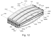
- the clamping component 101 When linked together with linkage components 32L, 32R, including components 34A, 34B, 36A, 36B and 38 (either left or right, further designated in The drawings with an “L” or a “R” respectively in the drawings), the clamping component 101 is assembled for uniform compressive belt clamping perpendicular to both the belt surface and the cross-beam across the whole of is elongated projection on to the belt 23, comprising overlapping portions 23A and 23B, an area exceeding the nominal belt width, 104 in Figure 12 .
- Box beam vertical elements 604 are both aligned, as at 604A and 604B in Figure 16 , with a corresponding pair of tension links 32L and 32R, each including upper and lower links 34 joined together by pins 38 for tension perpendicular to platen surface 602 without twist and with no substantial bending moment other than transverse to the length L and parallel to the width of the belt.
- the 2-layer embodiment of the cartridge as depicted in Figures 12 to 17 and in exploded view in Figure 15 is provided with a planar exterior surface on 2 sides which are adapted to interact with and perpendicular to the belt being spliced on the one side (the belt surface 702) and the source of pressure on the other (the pressure surface 703) extending over at least the full nominal width of the splice. These surfaces are preferably both flat and parallel.
- the cartridge is designed to be used in and with a plurality of closely abutting identical cartridges to form a belt splice platen-type array which may be as few as 2 and as many as 6 or more contiguous cartridges in operation.
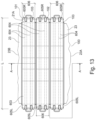
- each of modular components 100 includes a monolithic structure at each end, as at 605L and 605R in Figures I3 and I5, which extends across, and most preferably completely across, the full width 606 of each of the modular components 100.
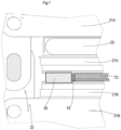
- the monolithic structures 605 are preferably engineered to spread loading between the surfaces 602, 603 and flanges 604 and pins 36A and 36B on each of the left and right ends of each modular component 100 as shown in Figures 7 and 16 .
- any misalignment of this tension force 609 and any bending or twisting moment is transferred between the upper and lower components 21A and 21B in a manner fully orthogonal to belt 23 and is restrained to bend components 21A and 21B solely about an axis parallel to and along the operational length of belt 23 without any twisting moment in the box or I-beam combination of surfaces, or, at least, to reduce same substantially.
- each modular component 100 is restrained with its height, H to remain perpendicular to belt 23.
- components 101, 102 and 103 are parallel to each other and in close proximity to each other at all times as shown in the drawings. As assembled, interconnection between immediately adjacent components 101, 102 and 103 is provided by the belt 23 itself.
- Modular component 200 may be fitted with a safety restraint bar or bars 614 which are adapted to be passed through passages 613 in flanges 604 in respective components 101, 102 and 103.
- flanges 604 may be fitted with clips 611 to maintain the bar 614 together with a cross-beam 21.
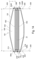
- Cartridge 701 is shown in Figure 17 with a next-to-belt surface 702 and an outer surface 703.
- Cartridge 701 is preferably formed with 3 distinct layers as shown in Figure 18 , whole long dimension L between its shell ends and width W match those of a modular component belt splicer as shown therein.
- the belt surface 702 of the cartridge 70l is provided with a base tray 802 including a heat transmissive layer 820 across its full extent which may be bent upwards at its lateral extremities form outside edges 823.
- the transmissive layer is preferably no more than a few mm thick.
- the transmissive layer 820 is preferably formed with a plurality of upstanding, preferably integral, internal fins or supports 821 in a closely packed array 822 which, together, form the heating layer of the cartridge. Outside edges 823 provide the inside extent of array 822. Fins 821 are minimally thin and may be as little as 1 mm in breadth and may be tapered to ensure both heat conductivity and structural support across the fin structure 822 to resist and preferably isolate compressive forces delivered by the cross-beams in a splicing operation.
- Inter-fin spacings are coupled, and preferably fully occupied, by a continuous electrical heating cable 801 in heat transmissive contact with the fin supports 821.
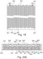
- Cable 821 lies in a serpentine pattern substantially throughout at least the projected area of the cartridge onto the belt splice as shown in Figures 18 on. Adjustments to a heating capacity and uniformity may be made by changing the fin spacing, engaging the serpentine wire in altemative fin lines as required (see Figure 18 and 19 ) or changing the wire or adjusting its heating capacity.
- the fin supports 821 extended internally at least as far as the extent of the heating cable 801 so as to bear the load, and preferably substantially all of the load, associated with process pressure throughout the whole of the heating and cooling process, plus assembly and dis-assembly operations, including variable bending and stresses associated the thin walled modular componentry.
- the serpentine heating cable 801 is a temperature and heat wattage controlled electrical cable flattened on 2 sides to form a race track configuration as shown in Figure 20b .
- the cable 801 is oriented vertically from both the belt splice 23 and the heat transmissive surfaces 820 and fully contacts that surface and each of the adjacent fin supports along its circular end and along its respective flat sides. Any spacings between the wire boundary and the fins or heat conductive surfaces may be filled on manufacture with a suitable heat structurally supporting conductive material as in Figures 19 , 20 and 21 .
- cable 801 is temperature reactive, with or without embedded temperature measurement devices, and interacts with minimally thin transmissive layer 820 for uniform delivery of process heat across the splice in conjunction with cable side or side wall 823 thermal conductivity and fins 821.
- the electrical cable 801 does not fully occupy the fin support array 821.
- Fin support array 821 may be sized to provide uniform heating and controlled process temperatures through adjacent fin supports and the heat transmissive layer 802 but with wire 801 not extending beyond the height of the fin supports 821. Corresponding adjustment of the next layer out is made so as not to pressure the conductive wire 801 during processing.
- a forced cooling layer 805, Figures 18 and 20 preferably lies vertically adjacent the heating layer in thermally transmissive contact with the fin array 821 so as to transmit most or all of the process pressure through to the fin array 821 and not the heating cable 801.
- the cartridge 701 includes an elongated outer container 805 adapted to contain both:
- External sources of process pressure, air or Water, may be connected to cooling tubes 825 and 805 through manifold connections 806 and 809 at either shell end of the thermal cartridge and thence to supply with or without an intervening manifold in the event that a non-serpentine cooling tube is used.
- the cartridge 701 includes end spacers (not shown) which close the tray 802 at each shell end so as to provide additional vertical structural support and spacing for the cartridge 701 against process pressures.
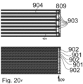
- the serpentine heating wire 801 is configured to pass down and back between every pair of fins 902 in the heating layer as a single wire or in a horizontal array of parallel heating wires.
- Cooling tubes 903 may be intercallated with heating wire 801 and fins 902 in a single layer as in Figure 19 .
- cooling tubes 901 lie within shell 805 and lie vertically outward from the heating array as shown in Figures 20 .
- Cooling tubes 903 preferably lie above wire 901 so that vertical alignment of the fins with the supports 904 between tubes 903 ensures maximum structural integrity against process pressures and bending.
- the cartridge also optionally includes a substantially rigid load bearing insulating third layer (not shown) either partially integral with or completely supported upon and in contact with at least the cooling layer so as to transmit process pressures from the cross-beam uniformly through the cooling layer and then the fin support array while insulating the heating/cooling elements from non-process heating losses.
- a substantially rigid load bearing insulating third layer (not shown) either partially integral with or completely supported upon and in contact with at least the cooling layer so as to transmit process pressures from the cross-beam uniformly through the cooling layer and then the fin support array while insulating the heating/cooling elements from non-process heating losses.
- the insulating layer is formed as a single amorphous layer prefabricated and assembled or poured in place, most preferably including reinforcing fibres and means to lighten the layer.
- the cartridge 701 may be readily and inexpensively fabricated on a component basis while remaining light in weight and optimal in heating and cooling delivery. easily manipulated in the field, the cartridge 701 assists in approaching a process fail safe condition by providing for ready and rapid replacement of a single cartridge in the most extreme conditions of storage, installation, process use and decommissioning.
- this abutment A may include a step of tongue and groove mating.
- the cartridge is formed as shown in Figures 20 wherein the heating and cooling layers are not both inter-callated with the fin supports so as to reduce thermal capacity while maintaining optimal process heat and pressure without deformation through rapid heating and cooling cycles while processing.
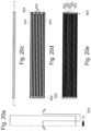
- Figures 20a and 20e show a top plan view of this embodiment, a partial end section, a side elevation, and an upper and lower section B-B and C-C.
- FIG 11a the cartridge is shown in an exploded view with a finned base plate 1. Expanded views of Figure 11a are shown in Figures 111b and 11c.
- Flattened heating cable Z is formed as a serpentine shape and inter-callated with the fins 5 so as to occupy alternate pairs of fin spacings 4, that is 3 fins per wire length, so as to lie in a single plane leaving unoccupied channels 6.
- Unoccupied channels 6 are preferably also in alternating pairs, 3 fins per channel.
- Unoccupied channels 6 may form a cooling structure by closure across the top of the fins 5 for the full width and breadth of the array. Cooling by externally applied air or water occurs by passage of the fluid along the length of the unoccupied channels in contact with vertical surface of 3 fins per passage.
- the unoccupied channels may include a serpentine cooling tube 7 as shown in Figures I2 and 13 for fluid flow A-A.
- the flattened sides of cooling tube 2 are in thermally transmissive contact with respective fins, preferably on both sides.
- a closely packed single plane heating and cooling array is provided and then closed into a single thermal unit by insulating cover plate 3.
- each length of each of the cable and the cooling tube are in surface to surface contact with fins on both flattened sides.
- Figure 13 shows a further expanded plan view of the heating/cooling array of Figure 12 in its cooling tube embodiment. Fins 5 occupy all spacings between back and forth runs of each serpentine of each of the heating cable.
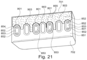
- Figure 21 shows a partial cross-section of a still further embodiment of the cartridge 701 of the invention.
- Belt surface 702 is not integrally formed with heat transmissive fins.
- heat transmissive material 851 is in a liquid or semi-liquid phase and poured into place, optionally between edges 823. While material 851 is still semi-liquid elongated heating cables 801 are embedded wholly or completely in the material 851 in a parallel array or as a serpentine. Continuing while material 851 is still semi-liquid cooling tubes 903 are embedded in the material 851 either directly adjacent cables 801 or vertically above said cables as in Figures 19 and 20 and allowed to harden into a structural support between the belt surface and surface 701.
- Cartridge 701 is then completed with structural heat insulating material 852 which may be poured into place either before or after material 851 has set or hardened.
- Cable 801 in Figure 21 is shown as a pair of electrical conductors 852 separated by a thermally adjustable electrical insulator 853 with the whole surrounded by electrical insulator 854.
- Structural material 852 may contain lightening and-reinforcing elements 855. Once hardened, materials 851 and 852 provide the supporting fin structural array of the invention providing full thermal conductivity with the belt surface and full insulation with the clamping components.
- the cable or the cooling tube may be composed of single straight lengths spliced together at each end.
Landscapes
- Engineering & Computer Science (AREA)
- General Engineering & Computer Science (AREA)
- Mechanical Engineering (AREA)
- Belt Conveyors (AREA)
- Lining Or Joining Of Plastics Or The Like (AREA)
- Structure Of Belt Conveyors (AREA)
- Auxiliary Devices For And Details Of Packaging Control (AREA)
Applications Claiming Priority (3)
| Application Number | Priority Date | Filing Date | Title |
|---|---|---|---|
| GBGB1516626.7A GB201516626D0 (en) | 2015-09-18 | 2015-09-18 | Modular belt splicer |
| EP16845434.6A EP3350475A4 (de) | 2015-09-18 | 2016-09-19 | Erweiterte komponentenbasierte förderbandspleissvorrichtung |
| PCT/CA2016/051097 WO2017045083A1 (en) | 2015-09-18 | 2016-09-19 | Advanced component based conveyor belt splicer |
Related Parent Applications (1)
| Application Number | Title | Priority Date | Filing Date |
|---|---|---|---|
| EP16845434.6A Division EP3350475A4 (de) | 2015-09-18 | 2016-09-19 | Erweiterte komponentenbasierte förderbandspleissvorrichtung |
Publications (2)
| Publication Number | Publication Date |
|---|---|
| EP4553339A2 true EP4553339A2 (de) | 2025-05-14 |
| EP4553339A3 EP4553339A3 (de) | 2025-09-24 |
Family
ID=54544506
Family Applications (2)
| Application Number | Title | Priority Date | Filing Date |
|---|---|---|---|
| EP16845434.6A Pending EP3350475A4 (de) | 2015-09-18 | 2016-09-19 | Erweiterte komponentenbasierte förderbandspleissvorrichtung |
| EP24215951.5A Pending EP4553339A3 (de) | 2015-09-18 | 2016-09-19 | Fortschrittliche komponentenbasierte förderbandspleissvorrichtung |
Family Applications Before (1)
| Application Number | Title | Priority Date | Filing Date |
|---|---|---|---|
| EP16845434.6A Pending EP3350475A4 (de) | 2015-09-18 | 2016-09-19 | Erweiterte komponentenbasierte förderbandspleissvorrichtung |
Country Status (8)
| Country | Link |
|---|---|
| US (1) | US20190113103A1 (de) |
| EP (2) | EP3350475A4 (de) |
| CN (4) | CN112984052B (de) |
| AU (4) | AU2016322039B2 (de) |
| CA (1) | CA2999072A1 (de) |
| CL (1) | CL2018000709A1 (de) |
| GB (1) | GB201516626D0 (de) |
| WO (1) | WO2017045083A1 (de) |
Families Citing this family (7)
| Publication number | Priority date | Publication date | Assignee | Title |
|---|---|---|---|---|
| GB201105764D0 (en) * | 2011-04-04 | 2011-05-18 | Shaw Almex Ind Ltd | Link connector for belt-splicer |
| DE102018208960A1 (de) * | 2018-06-06 | 2019-12-12 | Werner & Pfleiderer Industrielle Backtechnik Gmbh | Endlos-Förderband für einen Durchlauf-Backofen sowie Bandglied hierfür |
| CN111661649B (zh) * | 2020-06-27 | 2025-02-21 | 福建省农业机械化研究所(福建省机械科学研究院) | 等接触应力夹持输送装置 |
| CN112811116A (zh) * | 2021-01-28 | 2021-05-18 | 苏州工业园区智胜美自动化科技有限公司 | 一种具有减震功能的零部件加工用包装工装整机 |
| CN114275449B (zh) * | 2021-12-15 | 2022-11-01 | 郑州凯雪冷链股份有限公司 | 高效节能的冷库保温系统 |
| CN117357107B (zh) * | 2023-11-09 | 2024-10-15 | 河北地质大学 | 局部组织血氧监测装置 |
| CN118438686B (zh) * | 2024-05-29 | 2026-02-27 | 上海盛誉传动系统有限公司 | 一种热压装置及采用其进行输送带加工的方法 |
Citations (3)
| Publication number | Priority date | Publication date | Assignee | Title |
|---|---|---|---|---|
| DD148200A1 (de) | 1979-12-21 | 1981-05-13 | Emil Wiesner | Transportable vorrichtung zum vulkanisieren von foerderbaendern |
| WO2012135945A1 (en) | 2011-04-04 | 2012-10-11 | Shaw-Almex Industries Limited | Tension link for a belt splicer |
| WO2014172782A1 (en) | 2013-04-26 | 2014-10-30 | Shaw-Almex Industries Limited | Air-cooled belt splicer |
Family Cites Families (17)
| Publication number | Priority date | Publication date | Assignee | Title |
|---|---|---|---|---|
| GB425204A (en) * | 1934-07-07 | 1935-03-08 | W T Nicholson And Clipper Comp | Improvements in belt-fastener staple-clinching apparatus |
| GB1325063A (en) * | 1970-08-07 | 1973-08-01 | Hayden Nilos Ltd | Belt-fastening machines |
| US5181601A (en) * | 1990-10-09 | 1993-01-26 | Palmaer K V | Plastic conveyor belt with integral sideplate |
| DE4125055C2 (de) * | 1991-07-29 | 1996-07-11 | Lausitzer Braunkohle Ag | Kompaktvulkanisierpresse |
| US6695123B2 (en) * | 2001-12-21 | 2004-02-24 | Richwood Industries, Inc. | Conveyor belt cleaner blade |
| CN1322970C (zh) * | 2003-03-14 | 2007-06-27 | 姚禹肃 | 一种运输带接头方法 |
| CA2502086C (en) * | 2005-03-23 | 2012-01-24 | Shaw-Almex Industries Ltd. | Safety system for constraining crossbeams in a belt splicer |
| US20100126654A1 (en) * | 2007-03-30 | 2010-05-27 | Atsushi Katayama | Working apparatus, apparatus for applying adhesive tape, and tape member adding method |
| CL2008002214A1 (es) * | 2008-07-29 | 2009-01-02 | William Valenzuela Urrea Ricardo | Prensa portatil empalmadora para unir extremos de banda transportadoras de pvc o pu,operable en terreno por ser desmontable, comprende una estructura superior e inferior con perfiles livianos y medios de calentamiento; colchon de aire como mecanismo de presion y medios de apriete. |
| US8596622B2 (en) * | 2009-10-16 | 2013-12-03 | Laitram, L.L.C. | Rapid-release belt splicer and method of operation |
| CN101936626A (zh) * | 2010-04-08 | 2011-01-05 | 合肥美的荣事达电冰箱有限公司 | 一种翅片式蒸发器及其电冰箱 |
| DE102010036104B4 (de) * | 2010-09-01 | 2017-11-23 | Mlt Gmbh | Heizelement für eine Vulkanisierpresse mit nanoporöser Isolierschicht |
| CN202187430U (zh) * | 2011-07-18 | 2012-04-11 | 浙江华铁建筑安全科技股份有限公司 | 可转动贝雷专用接头 |
| CN202178430U (zh) * | 2011-08-08 | 2012-03-28 | 特通科技有限公司 | 堆栈式的连接器 |
| CN104454120A (zh) * | 2013-09-13 | 2015-03-25 | 天津博盛源化工有限公司 | 一种用于卧式冷却水箱的水管层 |
| CN203744580U (zh) * | 2014-02-20 | 2014-07-30 | 丽水学院 | 一种带翅片管及扭带强化的太阳能相变热水器 |
| CN204585655U (zh) * | 2015-05-04 | 2015-08-26 | 张家港市华申工业橡塑制品有限公司 | 导热式输送带硫化机 |
-
2015
- 2015-09-18 GB GBGB1516626.7A patent/GB201516626D0/en not_active Ceased
-
2016
- 2016-09-19 CA CA2999072A patent/CA2999072A1/en not_active Abandoned
- 2016-09-19 AU AU2016322039A patent/AU2016322039B2/en active Active
- 2016-09-19 WO PCT/CA2016/051097 patent/WO2017045083A1/en not_active Ceased
- 2016-09-19 CN CN202110158478.7A patent/CN112984052B/zh active Active
- 2016-09-19 EP EP16845434.6A patent/EP3350475A4/de active Pending
- 2016-09-19 CN CN201680054255.3A patent/CN108027013B/zh active Active
- 2016-09-19 US US15/761,171 patent/US20190113103A1/en not_active Abandoned
- 2016-09-19 CN CN202110158486.1A patent/CN112984053B/zh active Active
- 2016-09-19 EP EP24215951.5A patent/EP4553339A3/de active Pending
- 2016-09-19 CN CN202110158343.0A patent/CN112984051B/zh active Active
-
2018
- 2018-03-16 CL CL2018000709A patent/CL2018000709A1/es unknown
-
2020
- 2020-09-23 AU AU2020239703A patent/AU2020239703B2/en active Active
-
2021
- 2021-09-24 AU AU2021236550A patent/AU2021236550B2/en active Active
-
2024
- 2024-08-02 AU AU2024205476A patent/AU2024205476A1/en active Pending
Patent Citations (4)
| Publication number | Priority date | Publication date | Assignee | Title |
|---|---|---|---|---|
| DD148200A1 (de) | 1979-12-21 | 1981-05-13 | Emil Wiesner | Transportable vorrichtung zum vulkanisieren von foerderbaendern |
| WO2012135945A1 (en) | 2011-04-04 | 2012-10-11 | Shaw-Almex Industries Limited | Tension link for a belt splicer |
| US20140014275A1 (en) | 2011-04-04 | 2014-01-16 | Shaw-Amex Industries Limited | Tension link for a belt splicer |
| WO2014172782A1 (en) | 2013-04-26 | 2014-10-30 | Shaw-Almex Industries Limited | Air-cooled belt splicer |
Also Published As
| Publication number | Publication date |
|---|---|
| WO2017045083A1 (en) | 2017-03-23 |
| EP4553339A3 (de) | 2025-09-24 |
| AU2020239703B2 (en) | 2022-11-17 |
| EP3350475A4 (de) | 2019-05-22 |
| AU2024205476A1 (en) | 2024-08-22 |
| AU2020239703A1 (en) | 2020-10-15 |
| AU2016322039B2 (en) | 2021-06-24 |
| US20190113103A1 (en) | 2019-04-18 |
| CN112984053B (zh) | 2023-02-03 |
| AU2016322039A1 (en) | 2018-04-12 |
| CA2999072A1 (en) | 2017-03-23 |
| GB201516626D0 (en) | 2015-11-04 |
| CN108027013B (zh) | 2021-03-05 |
| CN112984051A (zh) | 2021-06-18 |
| CN108027013A (zh) | 2018-05-11 |
| CN112984052A (zh) | 2021-06-18 |
| CL2018000709A1 (es) | 2018-06-01 |
| CN112984053A (zh) | 2021-06-18 |
| CN112984052B (zh) | 2023-02-03 |
| CN112984051B (zh) | 2023-02-03 |
| AU2021236550A1 (en) | 2021-10-28 |
| AU2021236550B2 (en) | 2024-05-02 |
| EP3350475A1 (de) | 2018-07-25 |
Similar Documents
| Publication | Publication Date | Title |
|---|---|---|
| AU2021236550B2 (en) | Advanced component based conveyor belt splicer | |
| US7694495B2 (en) | Apparatus and method for making fluid filled units | |
| US10724601B2 (en) | Belt splicer | |
| US6228200B1 (en) | Belt press using differential thermal expansion | |
| US7882879B2 (en) | Apparatus for bonding rubber O-Rings and extrusions | |
| CA3036995A1 (en) | Sidewall bonder and method for bonding sidewalls to thermoplastic belts | |
| US7325580B2 (en) | Safety system for constraining crossbeams in a belt splicer | |
| KR200413897Y1 (ko) | 창틀 골재용 열융착장치의 클램프조립체 | |
| CN114161723A (zh) | 一种耐油抗老化的线束制备方法 | |
| RU2071421C1 (ru) | Переносной электрический вулканизатор | |
| CN114939990B (zh) | 一种焊接设备及可折叠片材组件产品的制造方法 | |
| EP2425962A1 (de) | Heizelement für eine Vulkanisierpresse mit nanoporöser Isolierschicht | |
| KR20250174364A (ko) | 이차전지 리드탭 열융착 장치 | |
| CN119403671A (zh) | 跟踪引导件结合机和将跟踪引导件结合到热塑性带的方法 | |
| CA2502086A1 (en) | Safety system for constraining crossbeams in a belt splicer | |
| KR20230057722A (ko) | 실링장치의 커터 열변형 유지구조 | |
| JPH0510888B2 (de) | ||
| WO2005084921A1 (en) | An improved blister forming / sealing system mechanism for a blistering machine and the blistering machine comprising the same | |
| ITBO20060341A1 (it) | Apparato di saldatura |
Legal Events
| Date | Code | Title | Description |
|---|---|---|---|
| PUAI | Public reference made under article 153(3) epc to a published international application that has entered the european phase |
Free format text: ORIGINAL CODE: 0009012 |
|
| STAA | Information on the status of an ep patent application or granted ep patent |
Free format text: STATUS: THE APPLICATION HAS BEEN PUBLISHED |
|
| AC | Divisional application: reference to earlier application |
Ref document number: 3350475 Country of ref document: EP Kind code of ref document: P |
|
| AK | Designated contracting states |
Kind code of ref document: A2 Designated state(s): AL AT BE BG CH CY CZ DE DK EE ES FI FR GB GR HR HU IE IS IT LI LT LU LV MC MK MT NL NO PL PT RO RS SE SI SK SM TR |
|
| REG | Reference to a national code |
Ref country code: DE Ref legal event code: R079 Free format text: PREVIOUS MAIN CLASS: F16G0003160000 Ipc: F16G0003100000 |
|
| PUAL | Search report despatched |
Free format text: ORIGINAL CODE: 0009013 |
|
| AK | Designated contracting states |
Kind code of ref document: A3 Designated state(s): AL AT BE BG CH CY CZ DE DK EE ES FI FR GB GR HR HU IE IS IT LI LT LU LV MC MK MT NL NO PL PT RO RS SE SI SK SM TR |
|
| RIC1 | Information provided on ipc code assigned before grant |
Ipc: F16G 3/10 20060101AFI20250819BHEP Ipc: B65G 15/30 20060101ALI20250819BHEP Ipc: F16G 3/16 20060101ALI20250819BHEP |
|
| RAP1 | Party data changed (applicant data changed or rights of an application transferred) |
Owner name: ALMEX CANADA LIMITED |