EP4553341A1 - Disque denté et transmission à courroie crantée avec un tel disque denté - Google Patents
Disque denté et transmission à courroie crantée avec un tel disque denté Download PDFInfo
- Publication number
- EP4553341A1 EP4553341A1 EP24208002.6A EP24208002A EP4553341A1 EP 4553341 A1 EP4553341 A1 EP 4553341A1 EP 24208002 A EP24208002 A EP 24208002A EP 4553341 A1 EP4553341 A1 EP 4553341A1
- Authority
- EP
- European Patent Office
- Prior art keywords
- toothed
- pulley
- teeth
- guide element
- toothed belt
- Prior art date
- Legal status (The legal status is an assumption and is not a legal conclusion. Google has not performed a legal analysis and makes no representation as to the accuracy of the status listed.)
- Pending
Links
Images


Classifications
-
- F—MECHANICAL ENGINEERING; LIGHTING; HEATING; WEAPONS; BLASTING
- F16—ENGINEERING ELEMENTS AND UNITS; GENERAL MEASURES FOR PRODUCING AND MAINTAINING EFFECTIVE FUNCTIONING OF MACHINES OR INSTALLATIONS; THERMAL INSULATION IN GENERAL
- F16H—GEARING
- F16H55/00—Elements with teeth or friction surfaces for conveying motion; Worms, pulleys or sheaves for gearing mechanisms
- F16H55/02—Toothed members; Worms
- F16H55/17—Toothed wheels
- F16H55/171—Toothed belt pulleys
-
- F—MECHANICAL ENGINEERING; LIGHTING; HEATING; WEAPONS; BLASTING
- F16—ENGINEERING ELEMENTS AND UNITS; GENERAL MEASURES FOR PRODUCING AND MAINTAINING EFFECTIVE FUNCTIONING OF MACHINES OR INSTALLATIONS; THERMAL INSULATION IN GENERAL
- F16G—BELTS, CABLES, OR ROPES, PREDOMINANTLY USED FOR DRIVING PURPOSES; CHAINS; FITTINGS PREDOMINANTLY USED THEREFOR
- F16G1/00—Driving-belts
- F16G1/28—Driving-belts with a contact surface of special shape, e.g. toothed
-
- F—MECHANICAL ENGINEERING; LIGHTING; HEATING; WEAPONS; BLASTING
- F16—ENGINEERING ELEMENTS AND UNITS; GENERAL MEASURES FOR PRODUCING AND MAINTAINING EFFECTIVE FUNCTIONING OF MACHINES OR INSTALLATIONS; THERMAL INSULATION IN GENERAL
- F16H—GEARING
- F16H7/00—Gearings for conveying rotary motion by endless flexible members
- F16H7/02—Gearings for conveying rotary motion by endless flexible members with belts; with V-belts
- F16H7/023—Gearings for conveying rotary motion by endless flexible members with belts; with V-belts with belts having a toothed contact surface or regularly spaced bosses or hollows for slipless or nearly slipless meshing with complementary profiled contact surface of a pulley
-
- F—MECHANICAL ENGINEERING; LIGHTING; HEATING; WEAPONS; BLASTING
- F16—ENGINEERING ELEMENTS AND UNITS; GENERAL MEASURES FOR PRODUCING AND MAINTAINING EFFECTIVE FUNCTIONING OF MACHINES OR INSTALLATIONS; THERMAL INSULATION IN GENERAL
- F16H—GEARING
- F16H7/00—Gearings for conveying rotary motion by endless flexible members
- F16H7/18—Means for guiding or supporting belts, ropes, or chains
- F16H2007/185—Means for guiding or supporting belts, ropes, or chains the guiding surface in contact with the belt, rope or chain having particular shapes, structures or materials
-
- F—MECHANICAL ENGINEERING; LIGHTING; HEATING; WEAPONS; BLASTING
- F16—ENGINEERING ELEMENTS AND UNITS; GENERAL MEASURES FOR PRODUCING AND MAINTAINING EFFECTIVE FUNCTIONING OF MACHINES OR INSTALLATIONS; THERMAL INSULATION IN GENERAL
- F16H—GEARING
- F16H55/00—Elements with teeth or friction surfaces for conveying motion; Worms, pulleys or sheaves for gearing mechanisms
- F16H55/32—Friction members
- F16H55/36—Pulleys
- F16H2055/363—Pulleys with special means or properties for lateral tracking of the flexible members running on the pulley, e.g. with crowning to keep a belt on track
Definitions
- the invention relates to a toothed pulley according to the preamble of claim 1. Furthermore, the invention relates to a toothed belt drive with such a toothed pulley, a two-wheeler with such a toothed belt drive and a toothed belt.
- Timing belts can transmit significantly higher torques than comparable flat or V-belts, but generally require guide elements to prevent them from slipping off the pulleys due to transverse forces. This is particularly the case with helical gears, which, while running smoother and quieter than straight gears, can be prone to slipping off the pulleys due to the inherent axial force component.
- straight-toothed timing belt drives safeguards against slipping due to transverse forces are important, as is the case with timing belt drives on two-wheelers.
- the belt itself must have a flanged pulley that protects against lateral Provide anti-slip guidance in interaction with the respective pulley.
- so-called self-guiding belts require longitudinally formed guide elements, such as ribs arranged longitudinally within the tooth gaps or longitudinally directed projections or recesses that engage with corresponding recesses or projections in the respective pulleys and provide longitudinal guidance.
- the EP 2 289 792 A1 shows a self-centering system in which the belt is designed with a recess or groove in the center of its toothing, and the timing belt pulley has a protruding centering rib or flange running centrally between the tooth flanks, which engages the groove of the timing belt as it rotates.
- the height of the centering rib is limited to the height of the teeth of the timing belt pulley.
- the maximum lateral guiding forces are also limited by the limited height of the centering rib.
- the EP 1724495 A1 discloses a toothed belt drive with a toothed belt having a longitudinal groove and a pulley formed with a guide element for axially guiding the toothed belt.
- the guide element can be designed as a ring manufactured separately from the pulley and split at at least one circumferential point.
- the abutting ring sections are positively or non-positively connected to one another to form a self-contained ring. The ring thus formed is held in a groove of the pulley.
- the disadvantage is that the design of the guide element, which uses elements for positive or non-positive connection to form a closed ring, is complex and therefore expensive to manufacture.
- a further process step is the additional connection of the guide element to form a self-contained guide ring.
- the invention is based on the object of providing a toothed pulley with a guide element for the lateral guidance of a toothed belt in a toothed belt drive, which can be manufactured cost-effectively due to its design features.
- an alternative solution to the prior art should be provided.
- reliable lateral guidance of the toothed belt should be ensured even with very large alignment tolerances between the toothed pulleys of a toothed belt drive.
- a toothed pulley with a guide element should be provided, with which, in conjunction with a toothed belt, the maximum power transmission can be maintained unchanged compared to a solution without a guide element.
- toothed pulley having the features of independent claim 1. Further solutions are achieved by a toothed belt drive having a toothed pulley according to the invention according to the features of claim 7, a toothed belt having the features of claim 9, and a bicycle having the features of claim 10.
- the present application relates to a toothed pulley comprising a toothed pulley body, a plurality of circumferentially arranged teeth, each pair of teeth being spaced apart by a tooth gap, and at least two guide elements, the guide element being arranged in the tooth gap.
- the width of the guide element is smaller than a tooth width.
- the guide element extends in a radial direction and is spaced circumferentially from the adjacent teeth.
- the guide element does not touch the adjacent teeth.
- the power transmission capacity of a timing belt that wraps around the pulley and meshes with the teeth is particularly advantageously not negatively affected by the guide element, since the contact area between the teeth of the pulley and the teeth of the timing belt can remain unchanged compared to a pulley without a guide element.
- the toothed disc and/or the guide elements can be made of plastic or metal.
- the toothed pulley can be constructed in one piece or in multiple parts.
- the toothed pulley is preferably constructed in multiple parts.
- the individual parts e.g., the base body of the toothed pulley and the guide elements, can thus be manufactured cost-effectively and using simple manufacturing processes.
- the production of multiple individual parts, which can subsequently be assembled or joined together to form a toothed pulley according to the invention, can lead to simpler and more cost-effective production, particularly in the case of particularly complex geometries or undercuts of the toothed pulley.
- the interdental space has openings facing the interior of the toothed disc over part of a tooth width for the removal of foreign bodies or dirt.
- the openings of the toothed disc according to the invention can advantageously prevent the accumulation of Contamination can be prevented, which can lead to interference in the meshing between the belt or its teeth and the toothed pulley, which can cause the belt to jump over the toothed pulley.
- the pulley has a pulley body, from which the teeth of the pulley can be designed to project axially on one or both sides.
- the pulley teeth are connected to the pulley body at the tooth base over only a portion of the tooth width. In addition to the resulting weight savings, this also allows for adequate support and torque transmission through the timing belt, depending on the specific load situation and power transmission, and also ensures reliable and clean removal of contaminants, as the projection creates correspondingly large openings in the tooth base area.
- the toothed pulley is symmetrically configured, so that the guide element is arranged centrally in the axial direction of the toothed pulley, and an opening extends from the toothed pulley body to the left in the axial direction, and an opening extends from the toothed pulley body to the right in the axial direction.
- the maximum depth or width of the left opening or the right opening results from subtracting the width of the toothed pulley body from the tooth width, divided by two.
- the tip radius of the guide element corresponds at least to the tip radius of the tooth.
- the tip radius of the guide element is up to 2 mm larger than the tip radius of the tooth.
- This design of the guide bar eliminates the need for flanged pulleys to guide the timing belt in the axial or transverse direction, while still achieving a very effective forced guidance of the timing belt.
- the guide element has a chamfer or rounded portion.
- the guide element can be configured to taper or be rounded in a wedge-shaped manner in the radial direction, with the width of the guide element increasing inward in the radial direction. This advantageously improves the engagement of the guide element in the corresponding recess of the timing belt when individual pulleys are misaligned or offset from one another. Additionally or alternatively, dirt and/or deposits can be directed in a targeted manner toward the openings for dirt removal.
- the toothed disc is designed in several parts and the guide elements are each arranged in a recess of the toothed disc.
- the spaces between the teeth of the pulley each have a recess in the pulley body for receiving a guide element.
- the guide elements can be arranged, accommodated, or fixed at a distance from the teeth of the pulley, so that the contact surface of the pulley teeth for force transmission into a timing belt can remain unchanged. This can be particularly advantageous for applications with particularly high power or force transmission and/or a simultaneously limited installation space.
- the recesses can also be connected to each other as a circumferential groove.
- the groove can run through the teeth of the toothed pulley, whereby the teeth of the toothed pulley are aligned in an axial direction. viewed from the left tooth segment and a right tooth segment.
- the effort required to manufacture the toothed disk can be simplified by a circumferential groove compared to individually arranged recesses in the interdental spaces.
- the guide elements are arranged spaced apart on at least one base body, wherein the base body can be inserted into the groove connecting the recesses in the toothed pulley.
- the base body can be annular or segmented to simplify assembly.
- the segments can also be arranged spaced apart from one another around the circumference of the toothed pulley.
- the number of guide elements corresponds to an integer divisor of the number of teeth on the toothed belt. In particular, with comparatively low axial forces, a small number of guide elements can be sufficient for reliable lateral guidance of the toothed belt.
- the mechanical weakening of the toothed belt can also be minimized by reducing the number of recesses introduced therein.
- the base body or the guide elements can have an oversize compared to the recesses or the groove of the toothed pulley. Additionally or alternatively, the guide elements or the base body can be connected to the toothed pulley in a form-fitting, force-fitting, or material-fitting manner. Examples of this include screw connections, welded connections, or adhesive connections. By firmly arranging the base bodies or the guide elements on the toothed pulley, an additional connection between the individual base bodies or guide elements can be eliminated.
- the number of guide elements corresponds at least to the number of segmented base bodies. In other words, each base body has at least one guide element.
- the present application also relates to a toothed belt drive with a toothed pulley according to the invention and a toothed belt, wherein at least two teeth of the toothed belt are divided by a recess into two toothed segments spaced apart from one another in the axial direction, wherein the guide element of the toothed pulley is designed to engage in the recess of the toothed belt and to guide the toothed belt in the axial direction.
- the aforementioned properties and advantages can thus be applied to any toothed belt drive, preferably one that can be used in a contaminated environment.
- the recesses of the toothed belt can be individually formed for each tooth.
- the toothed belt can have a circumferential groove, which can be manufactured cost-effectively.
- the number of guide elements corresponds to an integer divisor of the number of teeth of the timing belt.
- the present application also relates to a toothed belt in a toothed belt drive according to the invention.
- the application further relates to a bicycle with a toothed belt drive according to the invention.
- the aforementioned properties and advantages can be applied to a bicycle and its derivatives with a toothed belt drive according to the invention.
- the toothed belt drive of a bicycle is generally exposed to dusty or dirty environments without protection.
- the design according to the invention provides secure belt guidance and sufficient power transmission even in dirty conditions.
- the description of the above figures is given in cylindrical coordinates with a longitudinal axis X, a radial direction R perpendicular to the longitudinal axis X and a circumferential direction U circulating around the longitudinal axis X.
- the longitudinal axis X, the radial direction R and the circumferential direction U can also be referred to together as spatial directions X, R, U or as cylindrical spatial directions X, R, U.
- the schematically illustrated toothed pulley 1 has teeth 2 spaced apart from one another in the circumferential direction U by a tooth pitch.
- the toothed pulley 1 has a toothed pulley body 3, from which the teeth 2 project in the radial direction R and axial direction X.
- the teeth 2 have a tooth width Bz.
- a tooth gap 4 is formed between each two teeth 2.
- the toothed pulley 1 has a groove 7 running circumferentially in the circumferential direction U.
- the toothed pulley 1 has an opening 6 for dirt removal between two teeth 2, to the left and right of the toothed pulley body 3.
- the size of the left and right openings 6 together results from subtracting the width of the toothed pulley body 3 from the tooth width Bz. Since the toothed pulley 1 is symmetrical, the toothed pulley body 3 is arranged centrally. so that the opening 6 extends from the toothed pulley body 3 to the left in the axial direction X and from the toothed pulley body 3 to the right in the axial direction. Thus, the maximum depth of the left opening 6 or the right opening 6 results from subtracting the width of the toothed pulley body 3 from the tooth width B Z , divided by two.
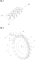
- the Figure 2 schematically shows a base body 8 with spaced-apart guide elements 5.
- the base body 8 is semicircular.
- the guide elements 5 are chamfered on the radially outer edges.
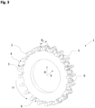
- Figure 3 shows the toothed disc 1 according to the invention from Figure 1 with guide elements 5 arranged in the interdental spaces 4.
- the guide elements 5 are Figure 2
- the base body 8 is arranged in the groove 7 of the toothed pulley 1.
- the arrangement of the guide elements 5 in each tooth space 4 over the entire circumference U of the toothed pulley 1 results from the arrangement of two semicircular base bodies 8 in the groove 7 of the toothed pulley 1.
- the height or tip radius of the guide elements 5 corresponds in the radial direction R to the height or tip radius of the teeth 2.
- Fig. 4 shows schematically a sectioned toothed belt 10 with a centrally extending recess 12 which divides the teeth 11 into a left and a right tooth segment.
- Fig. 5 shows schematically a partially illustrated toothed belt drive according to the invention, comprising the toothed pulley 1 from Figure 3 and the timing belt 10 Figure 4
- the teeth 2 of the toothed pulley 1 partially mesh with the teeth 11 of the toothed belt 10.
- the guide element 6 of the toothed pulley 1 is received in the recess 12 of the toothed belt 10 and guides the toothed belt 10 in the axial direction X.
Landscapes
- Engineering & Computer Science (AREA)
- General Engineering & Computer Science (AREA)
- Mechanical Engineering (AREA)
- Pulleys (AREA)
- Devices For Conveying Motion By Means Of Endless Flexible Members (AREA)
Applications Claiming Priority (1)
| Application Number | Priority Date | Filing Date | Title |
|---|---|---|---|
| DE102023211147.0A DE102023211147A1 (de) | 2023-11-10 | 2023-11-10 | Zahnscheibe sowie Zahnriementrieb mit einer solchen Zahnscheibe |
Publications (1)
| Publication Number | Publication Date |
|---|---|
| EP4553341A1 true EP4553341A1 (fr) | 2025-05-14 |
Family
ID=93257586
Family Applications (1)
| Application Number | Title | Priority Date | Filing Date |
|---|---|---|---|
| EP24208002.6A Pending EP4553341A1 (fr) | 2023-11-10 | 2024-10-22 | Disque denté et transmission à courroie crantée avec un tel disque denté |
Country Status (2)
| Country | Link |
|---|---|
| EP (1) | EP4553341A1 (fr) |
| DE (1) | DE102023211147A1 (fr) |
Citations (5)
| Publication number | Priority date | Publication date | Assignee | Title |
|---|---|---|---|---|
| EP1724495A1 (fr) | 2005-05-19 | 2006-11-22 | Matthias Pesch & Michael Ebner GbR | Transmission à courroie crantée et procédé de fabrication d'un poulie pour transmission à courroie crantée |
| EP2289792A1 (fr) | 2009-09-01 | 2011-03-02 | Wayne R. Lumpkin | Système à entraînement par courroie |
| US20180003273A1 (en) | 2016-07-01 | 2018-01-04 | Gates Corporation | Belt Drive System |
| EP3786483A2 (fr) * | 2019-08-30 | 2021-03-03 | ContiTech Antriebssysteme GmbH | Disque denté pourvu d'éléments de guidage |
| DE102021115976A1 (de) * | 2021-06-21 | 2022-12-22 | Arntz Beteiligungs Gmbh & Co. Kg | Riementrieb und Zahnriemen mit zahnseitigen Vorsprüngen |
-
2023
- 2023-11-10 DE DE102023211147.0A patent/DE102023211147A1/de active Pending
-
2024
- 2024-10-22 EP EP24208002.6A patent/EP4553341A1/fr active Pending
Patent Citations (5)
| Publication number | Priority date | Publication date | Assignee | Title |
|---|---|---|---|---|
| EP1724495A1 (fr) | 2005-05-19 | 2006-11-22 | Matthias Pesch & Michael Ebner GbR | Transmission à courroie crantée et procédé de fabrication d'un poulie pour transmission à courroie crantée |
| EP2289792A1 (fr) | 2009-09-01 | 2011-03-02 | Wayne R. Lumpkin | Système à entraînement par courroie |
| US20180003273A1 (en) | 2016-07-01 | 2018-01-04 | Gates Corporation | Belt Drive System |
| EP3786483A2 (fr) * | 2019-08-30 | 2021-03-03 | ContiTech Antriebssysteme GmbH | Disque denté pourvu d'éléments de guidage |
| DE102021115976A1 (de) * | 2021-06-21 | 2022-12-22 | Arntz Beteiligungs Gmbh & Co. Kg | Riementrieb und Zahnriemen mit zahnseitigen Vorsprüngen |
Also Published As
| Publication number | Publication date |
|---|---|
| DE102023211147A1 (de) | 2025-05-15 |
Similar Documents
| Publication | Publication Date | Title |
|---|---|---|
| EP2684790B1 (fr) | Galet guide-chaîne pour un dérailleur arrière d'une chaîne de bicyclette et dérailleur arrière doté d'un tel galet guide-chaîne | |
| EP1382872B1 (fr) | Plateau d'entraînement pour embrayage multi-disques | |
| EP2241781B1 (fr) | Engrenage, notamment train épicycloïdal doté d'une bride et d'une roue creuse | |
| EP1429054A2 (fr) | Engrenage planétaire | |
| EP3789635B1 (fr) | Roue dentée | |
| EP3786483A2 (fr) | Disque denté pourvu d'éléments de guidage | |
| WO2017054931A1 (fr) | Roue à denture hélicoïdale et segment destiné à une roue dentée | |
| DE102011087578A1 (de) | Ausgleichsrad mit Zapfenlagerung | |
| WO2023025343A1 (fr) | Ensemble de composants pour l'assemblage de transmissions planétaires à contact de roulement à niveau réel | |
| DE10238968A1 (de) | Wellenverbindungsverzahnung mit einem geradlinigen Zahnprofil | |
| DE102014010204B4 (de) | Getriebe mit einem Ritzel und einem Rad | |
| DE102007062363A1 (de) | Schaltgetriebe | |
| EP4198352B1 (fr) | Pignon satellite pour un train épicycloïdal, ainsi que porte satellites pour un tel pignon satellite | |
| EP4446614A1 (fr) | Disque dentaire | |
| EP4553341A1 (fr) | Disque denté et transmission à courroie crantée avec un tel disque denté | |
| DE102018218374B4 (de) | Getriebe | |
| AT500716B1 (de) | Verfahren zur ausgestaltung eines verbindungselementes und verbindungselement | |
| DE102013221860A1 (de) | Vorgespanntes Planetengetriebe | |
| EP1552175B1 (fr) | Joint de cardan de type rzeppa | |
| EP1806520B1 (fr) | Engrenage planétaire | |
| DE102021123372B4 (de) | Axialwälzlagereinheit mit zwischen kreisringförmigen Axiallagerscheiben angeordneten Wälzkörpern und einer lagerinternen Schmiermittelführung | |
| EP4467843A1 (fr) | Transmission à courroie dentée | |
| EP4495456A1 (fr) | Disque dentaire | |
| DE102024121603B3 (de) | Zahnriemenscheibe | |
| DE102023204844A1 (de) | Antriebsriemen |
Legal Events
| Date | Code | Title | Description |
|---|---|---|---|
| PUAI | Public reference made under article 153(3) epc to a published international application that has entered the european phase |
Free format text: ORIGINAL CODE: 0009012 |
|
| STAA | Information on the status of an ep patent application or granted ep patent |
Free format text: STATUS: THE APPLICATION HAS BEEN PUBLISHED |
|
| AK | Designated contracting states |
Kind code of ref document: A1 Designated state(s): AL AT BE BG CH CY CZ DE DK EE ES FI FR GB GR HR HU IE IS IT LI LT LU LV MC ME MK MT NL NO PL PT RO RS SE SI SK SM TR |
|
| STAA | Information on the status of an ep patent application or granted ep patent |
Free format text: STATUS: REQUEST FOR EXAMINATION WAS MADE |
|
| 17P | Request for examination filed |
Effective date: 20251114 |
|
| STAA | Information on the status of an ep patent application or granted ep patent |
Free format text: STATUS: EXAMINATION IS IN PROGRESS |
|
| 17Q | First examination report despatched |
Effective date: 20260319 |