EP4553355A1 - Dispositif de soulagement de pression d'explosion - Google Patents
Dispositif de soulagement de pression d'explosion Download PDFInfo
- Publication number
- EP4553355A1 EP4553355A1 EP23208339.4A EP23208339A EP4553355A1 EP 4553355 A1 EP4553355 A1 EP 4553355A1 EP 23208339 A EP23208339 A EP 23208339A EP 4553355 A1 EP4553355 A1 EP 4553355A1
- Authority
- EP
- European Patent Office
- Prior art keywords
- flame arrester
- rupture disc
- frame
- layers
- insulating material
- Prior art date
- Legal status (The legal status is an assumption and is not a legal conclusion. Google has not performed a legal analysis and makes no representation as to the accuracy of the status listed.)
- Pending
Links
Images


Classifications
-
- F—MECHANICAL ENGINEERING; LIGHTING; HEATING; WEAPONS; BLASTING
- F16—ENGINEERING ELEMENTS AND UNITS; GENERAL MEASURES FOR PRODUCING AND MAINTAINING EFFECTIVE FUNCTIONING OF MACHINES OR INSTALLATIONS; THERMAL INSULATION IN GENERAL
- F16K—VALVES; TAPS; COCKS; ACTUATING-FLOATS; DEVICES FOR VENTING OR AERATING
- F16K17/00—Safety valves; Equalising valves, e.g. pressure relief valves
- F16K17/02—Safety valves; Equalising valves, e.g. pressure relief valves opening on surplus pressure on one side; closing on insufficient pressure on one side
- F16K17/14—Safety valves; Equalising valves, e.g. pressure relief valves opening on surplus pressure on one side; closing on insufficient pressure on one side with fracturing member
- F16K17/16—Safety valves; Equalising valves, e.g. pressure relief valves opening on surplus pressure on one side; closing on insufficient pressure on one side with fracturing member with fracturing diaphragm ; Rupture discs
-
- F—MECHANICAL ENGINEERING; LIGHTING; HEATING; WEAPONS; BLASTING
- F16—ENGINEERING ELEMENTS AND UNITS; GENERAL MEASURES FOR PRODUCING AND MAINTAINING EFFECTIVE FUNCTIONING OF MACHINES OR INSTALLATIONS; THERMAL INSULATION IN GENERAL
- F16K—VALVES; TAPS; COCKS; ACTUATING-FLOATS; DEVICES FOR VENTING OR AERATING
- F16K17/00—Safety valves; Equalising valves, e.g. pressure relief valves
- F16K17/40—Safety valves; Equalising valves, e.g. pressure relief valves with a fracturing member, e.g. fracturing diaphragm, glass, fusible joint
-
- A—HUMAN NECESSITIES
- A62—LIFE-SAVING; FIRE-FIGHTING
- A62C—FIRE-FIGHTING
- A62C4/00—Flame traps allowing passage of gas but not of flame or explosion wave
-
- F—MECHANICAL ENGINEERING; LIGHTING; HEATING; WEAPONS; BLASTING
- F16—ENGINEERING ELEMENTS AND UNITS; GENERAL MEASURES FOR PRODUCING AND MAINTAINING EFFECTIVE FUNCTIONING OF MACHINES OR INSTALLATIONS; THERMAL INSULATION IN GENERAL
- F16K—VALVES; TAPS; COCKS; ACTUATING-FLOATS; DEVICES FOR VENTING OR AERATING
- F16K17/00—Safety valves; Equalising valves, e.g. pressure relief valves
- F16K17/40—Safety valves; Equalising valves, e.g. pressure relief valves with a fracturing member, e.g. fracturing diaphragm, glass, fusible joint
- F16K17/403—Safety valves; Equalising valves, e.g. pressure relief valves with a fracturing member, e.g. fracturing diaphragm, glass, fusible joint with a fracturing valve member
Definitions
- the present invention relates to a device for the explosion pressure relief of a container, a housing, an enclosure, a line or the like in which an explosive mixture, in particular an explosive atmosphere, is present or can arise.
- Explosive mixtures may be present or formed in containers, housings, and enclosures, for example, in production facilities, pipes, or other materials during storage or production of goods.
- the mixture may be intentional, but it may also be caused by error or by accident.
- the mixture can ignite unintentionally.
- the container, housing, enclosure, pipe, etc. will then explode.
- Such an explosion can cause devastating personal injury and property damage. This can result in serious production downtime.
- explosion venting devices are advisable and, in some cases, even required.
- the device is placed over an opening in the object or device to be protected.
- the bursting disc of the explosion venting device closes this opening.
- the bursting disc opens and releases the opening through which gases from the object to be protected
- the flame arrester is connected to the rupture disc in the Q-Tube or Q-Box.
- This consists of several layers of stainless steel mesh held in place by a cage.
- the cage which holds the layers of stainless steel mesh of the flame arrester and the layers of stainless steel mesh, and the rupture disc enclose a space into which the rupture disc opens.
- the arrangement of the flame arrester in the flow path behind the rupture disc has proven successful in the past for several reasons.
- the flame arrester cannot be contaminated by substances, particularly dust, present in the object or device to be protected.
- the flame arrester arranged behind the rupture disc can be designed to provide a large relief opening.
- the relief opening of the flame arrester can be significantly larger than the relief opening of the opened rupture disc, whereby the flow velocities of the gases through the flame arrester can be lower than the flow velocities in the area of the rupture disc, which facilitates the cooling of the hot gases and the extinguishing of the flames.
- the invention is based on the object of proposing a device for explosion pressure relief in which contamination of the flame arrester from the outside is not possible and which requires less space than the known Q-pipe and the known Q-box.
- the bursting disc is arranged behind the flame arrester in the direction in which gases pass through the device in the event of pressure relief.
- the flame arrester is thus protected from external influences by the rupture disc.
- the flame arrester of the device according to the invention is not protected in the direction of the volume to be protected from the influences of the processes taking place there.
- this is not a problem that can arise in every application.
- the flame arrester can be protected by a non-pressure-resistant cover, for example a film.
- the device according to the invention is also not as large-volume as the known Q-Box or Q-Tube. This applies in particular in cases where the flame arrester essentially forms a cuboid block arranged essentially parallel to the rupture disc. The distance between the flame arrester and the rupture disc can then be smaller compared to the distance for a Q-Tube or Q-Box. Although the flow-through area of the flame arrester is then smaller than that of the rupture disc, a corresponding design of the relief area of the rupture disc and the flame arrester can ensure sufficient flow velocities in the event of a venting event.
- the flame arrester it is also possible for the flame arrester to be shaped, for example curved, opposite to the direction in which gases pass through the device in the event of pressure relief. In contrast to a flat flame arrester shape, the flame arrester can then have a larger flow-through area. Since the bursting disc is generally arranged in the plane of the outer wall of the container, housing, enclosure, line or similar to be protected, the flame arrester then projects inwards and not outwards beyond the outer wall. This allows the container, housing, enclosure, line or similar to be protected to be designed more compactly.
- the flame arrester may comprise one or more layers of a knitted fabric, woven fabric, or the like, made of a material that can absorb heat well, for example, stainless steel threads.
- the layer or layers may be enclosed by a frame.
- the layer or layers may be held by the frame.
- the frame may be formed from one or more sections with a C-shaped profile. An edge of the one or more layers may be enclosed by the section or sections with the C-shaped profile. Legs of the C-shaped profile can rest on a top and a bottom side of the layer(s).
- the flame arrester can have several through holes in the area of the edge. Screws or other fastening devices can be passed through these through holes, allowing the flame arrester to be attached to the edge of the relief opening in the object or device to be protected in such a way that the layer or layers cover the relief opening in the object or device to be protected.
- the through holes can be provided in the upper leg of the C-profile, in the lower leg of the C-profile, and in the layer or layers.
- Sleeves can be inserted into the through holes in the layer or layers, which are connected to the upper leg on the one hand and to the lower leg of the C-profile on the other. Because the sleeves pass through the through holes in the layer or layers, the frame and the layer or layers are connected to one another. The layer or layers are thus held more or less loosely tensioned in the frame and cannot fall out of the frame.
- Machine housings or enclosures for production facilities often serve to protect the surrounding area from noise emissions.
- the noise generated within the machine or production facility is prevented from propagating by the housing or enclosure.
- the housings and enclosures are often designed accordingly. They can be multi-layer walls or walls with sound insulation that prevents the propagation of noise.
- a weak point in the sound insulation concepts of such housings or enclosures is often the device for Explosion venting devices. These devices often incorporate fabric flame arresters and rupture discs that open when pressure rises within the enclosure, allowing explosion pressure to be released without the enclosure or housing blowing apart.
- the flame arrester prevents flames from escaping from the enclosure or housing. Neither the rupture disc nor the flame arrester are designed to protect the surrounding area from noise emissions. Therefore, noise can escape from such devices and cause unwanted noise pollution in the surrounding area.
- a device for explosion pressure relief according to the invention is therefore to be improved so that it offers improved sound insulation.
- At least one layer of a sound-insulating insulating material can be arranged on the bursting disc of the explosion pressure relief device on a side facing the flame arrester or a side facing away from the flame arrester.
- the insulation material can essentially be any material suitable for sound insulation. Particularly suitable is one that is at least normally flammable, deformable or flexible, highly resistant to environmental influences such as sunlight or heat, absorbs little or no liquid, and/or is closed-cell.
- the insulation material can be PU foam, silicone foam, or EPDM-based insulation.
- the layers can consist of the same or different insulating materials.
- the deformability of the insulation material or materials is particularly advantageous when the layers are firmly connected to the rupture disc and are therefore deformed together with the rupture disc when it bursts.
- the insulation material has low tensile strength, particularly in the areas where the rupture disc's predetermined breaking lines are provided, so that it can tear quickly when the rupture disc bursts. This can prevent the insulation material from preventing or delaying the rupture of the rupture disc.
- the insulation material can also have predetermined breaking lines.
- a spacer is preferably provided between an edge of the rupture disc intended for fastening the rupture disc and the flame arrester. This spacer establishes a distance between the rupture disc and the flame arrester that corresponds to the thickness of the layer or layers of insulation material. The spacer then creates a space between the flame arrester and the rupture disc, which is filled by the layer or layers of insulation material or materials.
- the spacer can be a frame that can have a C-shaped profile that opens outwards.
- the rupture disc can have all the features that a European patent application 23178734.2 as an invention described rupture disc.
- the rupture disc of a device according to the invention can be round or rectangular.
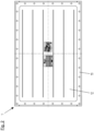
- the embodiment of a device 1 for venting explosion pressure in a container shown in the figures comprises a flame arrester 11, a bursting disc 12, a sound-absorbing insulating material 13, a spacer 14, seals 15, screws 16, washers 17, nuts 18 and a counter frame 19.
- the device 1 is shown in the illustrations of the Figures 1 and 3 mounted on a wall 2 of the container, which is protected against an uncontrolled explosion by the device 1.
- the device 1 covers and closes a relief opening in the wall 2 of the container.
- Through holes 21 are provided in one edge of the relief opening in the wall 2 of the container, which are used for fastening the device 1 to the wall.
- a seal 15 is placed around the edge of the opening in the wall 2 of the container.
- the flame arrester 11 is arranged on this seal 15.
- the flame arrester 11 has a rectangular frame 111 and several layers 112 of a knitted fabric made of stainless steel threads or wires.
- the frame 111 runs around the relief opening in the wall 2 of the container and is composed of several sections with a C-shaped profile. Legs 1111 of the profile point inward.
- the 112 layers which are in the Fig. 3 not shown individually but only as a block, are covered on their side facing the interior of the container and the side facing away from the container by a wide-meshed wire grid 114, which prevents the layers from sagging in a horizontal arrangement or from lateral displacement of the layers in a vertical arrangement.
- Through holes 1112, 1121 are also provided in the legs 1111 of the frame 111 and in the layers 112, aligned with the holes 21 in the wall of the container.
- a sleeve 113 is inserted into each of these through holes 1112, 1121.
- These sleeves 113 can be connected to the legs 1111 of the frame 111, for example, by form-fitting and/or welding. In particular, when the sleeves 113 are connected to the legs 1111, the layers 112 of the knitted fabric are also firmly connected to the frame 111.
- a screw 16 for fastening the device 1 to the wall 2 can be passed through each of the sleeves 113 inserted into the through holes 1112, 1121, which will be explained in more detail.
- a further seal 15 is placed on the leg 1111 on the side of the frame 111 of the flame arrester 11 facing away from the container, which seal can be identical to the seal 15 arranged between the flame arrester 11 and the wall 2.
- the spacer 14 is connected to this further seal 15.
- the spacer 14 is formed from a frame composed of sections with a C-profile. Unlike the frame 111 of the flame arrester 11, the legs 141 of the spacer 14 are directed outwards. The legs 141 have through holes that are aligned with the through holes in the edge of the wall 2 and the through holes in the flame arrester 11.
- the rupture disc 12 is placed on the spacer 14.
- This comprises a frame 121 and a sealing part 122.
- the frame 121 of the rupture disc 12 is made from sections of sheet metal strips bent by 180°, which are placed on the edge of the sealing part 122.
- the sealing part is a substantially rectangular, specially prepared sheet metal blank that closes the container's relief opening during normal operation. Through holes aligned with the holes in the wall 2 are provided in both the frame 121 and the edge of the sealing part 122.
- Screws 16 are inserted through these aligned through holes and secured with nuts 18 on the inside of wall 2. Washers 17 are provided between the heads of screws 16 and the counter frame 19, as well as between nuts 18 and wall 2. Thus, device 1 is attached to the wall.
- the sound-absorbing insulation layer 13 is attached to the side of the sealing part 122 of the rupture disk 12 facing the flame arrester 11. It can be glued to this side of the sealing part 122.
- the insulation material is a deformable, closed-cell plastic.
- the thickness of the layer 13 is selected such that it extends almost over the entire height of the spacer 14. In the illustrated embodiment, the layer 13 completely fills the space within the spacer 14. However, it is also possible for the layer 13 not to contact the spacer over its entire layer thickness. This can facilitate the opening of the rupture disk in the event of a pressure relief event. It is possible for a gap to be provided between the layer 13 and the spacer 14 that widens in the direction of the flame arrester 11.
- the rupture disc 12 opens, and the pressure in the container can be relieved by the escape of the medium present in the container. If the high pressure in the container is caused by an explosion, the flames from the explosion are extinguished by the flame arrester, and the non-combustible and cooled gases can escape through the opened rupture disc.
- the container and the sound-insulated sealing part 112 absorbs sound waves generated in the container and thus prevents noise from escaping from the container to the outside.
- device 1 takes up little space and is equally or more suitable for many applications than the known Q-Tube or Q-Box. For other applications, however, the known solutions are more suitable.
Landscapes
- Engineering & Computer Science (AREA)
- General Engineering & Computer Science (AREA)
- Mechanical Engineering (AREA)
- Health & Medical Sciences (AREA)
- Public Health (AREA)
- Business, Economics & Management (AREA)
- Emergency Management (AREA)
- Gas-Insulated Switchgears (AREA)
Priority Applications (2)
| Application Number | Priority Date | Filing Date | Title |
|---|---|---|---|
| EP23208339.4A EP4553355A1 (fr) | 2023-11-07 | 2023-11-07 | Dispositif de soulagement de pression d'explosion |
| US18/934,718 US20250146589A1 (en) | 2023-11-07 | 2024-11-01 | Explosion pressure relief device |
Applications Claiming Priority (1)
| Application Number | Priority Date | Filing Date | Title |
|---|---|---|---|
| EP23208339.4A EP4553355A1 (fr) | 2023-11-07 | 2023-11-07 | Dispositif de soulagement de pression d'explosion |
Publications (1)
| Publication Number | Publication Date |
|---|---|
| EP4553355A1 true EP4553355A1 (fr) | 2025-05-14 |
Family
ID=88745678
Family Applications (1)
| Application Number | Title | Priority Date | Filing Date |
|---|---|---|---|
| EP23208339.4A Pending EP4553355A1 (fr) | 2023-11-07 | 2023-11-07 | Dispositif de soulagement de pression d'explosion |
Country Status (2)
| Country | Link |
|---|---|
| US (1) | US20250146589A1 (fr) |
| EP (1) | EP4553355A1 (fr) |
Citations (1)
| Publication number | Priority date | Publication date | Assignee | Title |
|---|---|---|---|---|
| DE102006029356B3 (de) * | 2006-06-27 | 2008-01-31 | Pii Pipetronix Gmbh | Druckablassvorrichtung |
Family Cites Families (20)
| Publication number | Priority date | Publication date | Assignee | Title |
|---|---|---|---|---|
| US2068421A (en) * | 1934-11-05 | 1937-01-19 | Frank V Long | Flame arrester |
| US2366669A (en) * | 1941-11-10 | 1945-01-02 | Hooker Electrochemical Co | Safety device for combustion chambers |
| US2571961A (en) * | 1948-03-19 | 1951-10-16 | Standard Oil Dev Co | Safety device for pressure vessels |
| US2801768A (en) * | 1954-12-20 | 1957-08-06 | Westinghouse Electric Corp | Explosion-proof enclosure |
| US3398571A (en) * | 1965-11-26 | 1968-08-27 | Navy Usa | Explosive opening of metal diaphragms |
| US3817263A (en) * | 1969-12-06 | 1974-06-18 | Dynamit Nobel Ag | Device for the inflation of safety cushions in vehicles |
| US4067154A (en) * | 1975-02-20 | 1978-01-10 | Fike Metal Products Corporation | Instantaneous venting, non-frangible burst panel structure |
| US4342988A (en) * | 1980-01-25 | 1982-08-03 | Continental Disc Corporation | Rupture disc alarm system |
| USRE34308E (en) * | 1980-01-25 | 1993-07-13 | Continental Disc Corporation | Rupture disc alarm system |
| US4612739A (en) * | 1981-12-07 | 1986-09-23 | Continental Disc Corporation | Low pressure venting panel |
| US4484690A (en) * | 1982-03-08 | 1984-11-27 | Service Machine Co. | Flame arresting ventilated wall for an explosion-proof enclosure |
| US5155471A (en) * | 1991-06-21 | 1992-10-13 | Bs&B Safety Systems, Inc. | Low pressure burst disk sensor with weakened conductive strips |
| US5191990A (en) * | 1991-06-24 | 1993-03-09 | Bs&B Safety Systems, Inc. | Flash gas venting and flame arresting apparatus |
| US6065773A (en) * | 1996-01-19 | 2000-05-23 | Klinger; Barney | Gas pressure restraint, sensing and release systems |
| JP3613727B2 (ja) * | 2001-09-06 | 2005-01-26 | 東洋紡績株式会社 | 成形性に優れた吸音材 |
| DE102010016782B4 (de) * | 2010-05-04 | 2016-12-08 | R.Stahl Schaltgeräte GmbH | Druckentlastungsvorrichtung für druckfest gekapselte Gehäuse |
| DE102014116149A1 (de) * | 2014-11-06 | 2016-05-12 | R. Stahl Schaltgeräte GmbH | Flammenschutzfilter aus einer Anzahl von Schichtenfolgen sowie Anordnungen von Flammenschutzfiltern und deren Verwendung |
| DE102017112147A1 (de) * | 2017-06-01 | 2018-12-06 | R. Stahl Schaltgeräte GmbH | Gehäuse mit eingegossener Druckentlastung |
| DE102018119144A1 (de) * | 2018-08-07 | 2020-02-13 | R. Stahl Schaltgeräte GmbH | Druckentlastungseinrichtung und Gehäuse mit einer solchen |
| DE102019113193A1 (de) * | 2019-05-17 | 2020-11-19 | R. Stahl Schaltgeräte GmbH | Baukastensystem zum Herstellen eines Gehäuses |
-
2023
- 2023-11-07 EP EP23208339.4A patent/EP4553355A1/fr active Pending
-
2024
- 2024-11-01 US US18/934,718 patent/US20250146589A1/en active Pending
Patent Citations (1)
| Publication number | Priority date | Publication date | Assignee | Title |
|---|---|---|---|---|
| DE102006029356B3 (de) * | 2006-06-27 | 2008-01-31 | Pii Pipetronix Gmbh | Druckablassvorrichtung |
Also Published As
| Publication number | Publication date |
|---|---|
| US20250146589A1 (en) | 2025-05-08 |
Similar Documents
| Publication | Publication Date | Title |
|---|---|---|
| DE10326150B4 (de) | Dauerbrandsichere Flammensperre | |
| DE102006053579A1 (de) | Laserschutzvorrichtung mit Sicherheitsabschaltung | |
| DE3902245A1 (de) | Vibrationsfestes aufbrechbares druckentlastungselement | |
| EP3373362B1 (fr) | Dispositif de boîtier pourvu d'au moins une unité électrique présentant un danger de surchauffe | |
| DE112016001608T5 (de) | Vakuum-Wärmedämmkörper | |
| EP1559468A1 (fr) | Tamis pour protéger une bouche d'aspiration | |
| DE102012102468B4 (de) | Explosionsschutz mit Umhausung | |
| DE2022978A1 (de) | Anordnung mit einer in einem Gehaeuse untergebrachten Einrichtung | |
| DE3541442C2 (fr) | ||
| EP1559467A1 (fr) | Tamis pour protéger une bouche d'aspiration | |
| EP4553355A1 (fr) | Dispositif de soulagement de pression d'explosion | |
| EP0033085B1 (fr) | Système de fermeture à isolation thermique pour ouvertures de décharge de pression dans des parois de séparation, notamment dans des bâtiments pour réacteurs nucléaires | |
| DE3728055C2 (de) | Kombinations-Schutzraum | |
| DE3518724A1 (de) | Schutztuer | |
| DE29611396U1 (de) | Schutzvorrichtung | |
| DE4210901A1 (de) | Explosionsgeschützte Stahlbetonraumzelle, insbesondere Stahlbetonraumzellentrafostation | |
| DE202018106804U1 (de) | Aufbewahrungsbehälter und Absorberelement für einen Aufbewahrungsbehälter | |
| EP0076958A2 (fr) | Elévateur protégé contre l'explosion | |
| DE2822271C2 (fr) | ||
| AT507409B1 (de) | Flammfilter | |
| EP1387020A2 (fr) | Trappe de visite | |
| DE19837613A1 (de) | Transportbehälter | |
| EP2927135B1 (fr) | Unité de support d'un dispositif d'emballage sous vide | |
| DE202012013340U1 (de) | Rauchabzugseinrichtung | |
| DE2614893A1 (de) | Feuerhemmendes sperrelement |
Legal Events
| Date | Code | Title | Description |
|---|---|---|---|
| PUAI | Public reference made under article 153(3) epc to a published international application that has entered the european phase |
Free format text: ORIGINAL CODE: 0009012 |
|
| STAA | Information on the status of an ep patent application or granted ep patent |
Free format text: STATUS: THE APPLICATION HAS BEEN PUBLISHED |
|
| AK | Designated contracting states |
Kind code of ref document: A1 Designated state(s): AL AT BE BG CH CY CZ DE DK EE ES FI FR GB GR HR HU IE IS IT LI LT LU LV MC ME MK MT NL NO PL PT RO RS SE SI SK SM TR |
|
| STAA | Information on the status of an ep patent application or granted ep patent |
Free format text: STATUS: REQUEST FOR EXAMINATION WAS MADE |
|
| 17P | Request for examination filed |
Effective date: 20251114 |